
Related Manuals for designer's image 211-4578


Summary of Contents for designer's image 211-4578
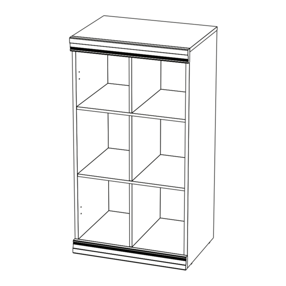
- Page 1 Cabinet with Cubes Assembly Instructions Reference # Finish 211-4578 4030 White 211-4579 4087 Java 211-4580 4050 Cottage 211-4679 14597 Charcoal Tools Needed: hammer screwdriver 01-13959-00 11/20...
-
Page 2: Safety Precautions
SAFETY PRECAUTIONS WARNING • This unit contains small parts which could be a choking hazard for small children. Children should be STOP under adult supervision at all times or serious injury could occur. • Always unload unit prior to moving the unit. The weight of personal belongings can cause the unit to become unstable and either tip or collapse. - Page 3 HARDWARE (H3) x 14 (H4) x 4 (H5) x 6 (H1) x 12 (H2) x 12 (H6) x 20 short dowel wide dowel long dowel cam post cam lock small nail 6 mm x 30 mm 8 mm x 30 mm 6 mm x 60 mm (H10) x 1 (H12) x 1...
-
Page 4: Description Quantity
DESCRIPTION QUANTITY left side panel right side panel top shelf bottom shelf vertical dividers middle shelves back panel trim finished unfinished edge edge Unfinished edges are shaded in gray in the illustrations throughout this document. It is important to understand how finished edges go together. Take a moment to lay out all the wood pieces and note the finished and unfinished (raw wood) edges. - Page 5 STEP 1 (H2) (H3) (H1) (H4) (H3) x 8 (H4) x 2 (H1) x 4 (H2) x 4 short dowel wide dowel cam post cam lock 6 mm x 30 mm 8 mm x 30 mm 1. Secure cam posts (H1) into holes as shown. PLEASE NOTE: Cam post is secure when threads on screw are not showing. 2.
- Page 6 STEP 2 (H4) (H3) (H2) (H1) (H2) (H3) x 3 (H4) x 2 (H1) x 4 (H2) x 8 short dowel wide dowel cam post cam lock 6 mm x 30 mm 8 mm x 30 mm 1. Secure cam posts (H1) into holes as shown. PLEASE NOTE: Cam post is secure when threads on screw are not showing. 2.
- Page 7 STEP 3 (H3) (H5) (H5) (H3) x 3 (H5) x 6 short dowel long dowel 6 mm x 30 mm 6 mm x 60 mm 1. Push SHORT dowels (H3) into the edge holes of one of the vertical dividers (E) as shown. 2.
- Page 8 STEP 4 (H5) (H5) 1. Push middle shelf (F) over the exposed long dowels (H5) of one of the vertical dividers (E) as shown. 2. Push the second vertical divider (E) with long dowels over exposed dowels as shown. 3. Push the second middle shelf (F) over the exposed long dowels (H5) of the vertical divider (E) as shown.
- Page 9 STEP 5 (H3) 1. Push the last vertical divider (E) with the short dowels (H3) over the exposed dowels as shown. 2. Push the bottom shelf (D) onto the short dowels (H3) as shown.
- Page 10 STEP 6 1. Align side panels (A & B) with appropriate holes as shown and install. 2. Tighten cam locks to secure side panels to bottom shelf (D).
- Page 11 STEP 7 1. Align top shelf (C) with appropriate holes as shown and install. 2. Tighten cam locks to secure side panels (A & B) to top shelf.
- Page 12 STEP 8 (H6) x 20 (H7) x 4 small nail nail-on foot 1. Place back panel (G) onto unit (making sure the finished side of backer faces down) and center horizontally and vertically. 2. Nail the back panel (G) into position using small nails (H6). Avoid angling nails. 3.
- Page 13 STEP 9 NOTE: Thicker edges of trim should be positioned towards the top and bottom ends of the unit unless stacking, then choose either option 1 or 2 for the adjoining trim preference. option 1 option 2 (H1) x 4 cam post 1.
- Page 14 STEP 10 WALL (H11) (H12) (H9) (H10) (H9) (H10) x 1 (H12) x 1 (H9) x 2 (H11) x 1 small screw long screw back anchor nylon zip tie (H8) x 4 #8 x 1/2 in. #8 x 1-1/2 in. cover cap 1.
- Page 15 STEP 11 (H14) x 8 (H13) x 2 medium screw stacking bracket #8 x 7/8 in. 1. NOTE: If stacking this unit, align the units on top of each other as shown. 2. Install stacking brackets (H13) to the back side of the units using the stacking screws (H14). 3.
Need help?
Do you have a question about the 211-4578 and is the answer not in the manual?
Questions and answers