
Related Manuals for Amada ZH-50


Summary of Contents for Amada ZH-50
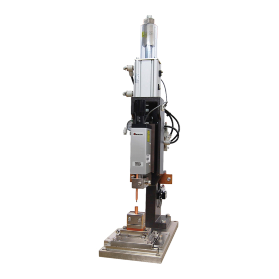
- Page 1 AIR DRIVING UNIT FOR PRESSURE FOLLOW-UP MECHANISM ELEMENT ZH-50 OPERATION MANUAL Z06M0871E-06...
-
Page 2: Table Of Contents
ZH-50 Thank you for purchasing our Air Driving Unit for Pressure Follow-Up Mechanism Element ZH-50. This operation manual describes its method of operation and precautions for use. Read this operation manual carefully prior to use. Store appropriately for ready reference. -
Page 3: Special Precautions
ZH-50 1. Special Precautions (1) Safety Precautions CAUTION ! Before using, be sure to read this operation manual to operate this machine correctly. This operation manual may include some items that do Denotes operations and practices not correspond to your use. However,... - Page 4 ZH-50 DANGER ! Do not disassemble, repair, or modify this machine in any case. Otherwise, an electric shock or injury will occur. When internal inspection or repair is required, make contact with us. WARNING ! Do not put your hands between the electrodes.
- Page 5 ZH-50 CAUTION ! Do not splash water on the product. Water splashed over the electric parts can cause electric shock and short circuits. Do not give excessive force to connecting cables. Do not bend, pull, or pinch any cable forcibly. If the cable is damaged, it will cause an electric shock, short circuit, or firing.
-
Page 6: Precautions For Handling
ZH-50 (2) Precautions for Handling Set the cylinder cover on when operating the cylinder to avoid fingers to be caught in the cylinder stopper. In this machine, the linear guide (linear bushing) is used vertically. Accordingly, grease or oil may drip, but this is not an accident. In particular, when a new machine is used, lots of grease of oil will drip. -
Page 7: Features
ZH-50 2. Features All-round unit suitable for diversified production workshops This model is applicable to your various production environments in the range of manual operation machine to labor-saving automatic machine. Applicable to various welding by combining with pressure... -
Page 8: Name And Functions Of Each Section
ZH-50 3. Name and Functions of Each Section (1) Explanation of Each Part 3. Name and Functions of Each Section... - Page 9 ZH-50 (1) Cylinder stopper fixing nut Tighten this nut to fix the cylinder stopper after the cylinder stroke adjustment. (Use a spanner with 32-mm across flats.) ! CAUTION Be sure to fix the cylinder stopper during use. Otherwise, the machine will be damaged.
-
Page 10: Follow-Up Mechanism Mounting Plate
ZH-50 (2) Follow-Up Mechanism Mounting Plate This part is used to various mount follow-up mechanisms. For V-type (standard) : t25 For VPW-M : t20 CAP spot facing, 5.5 deep 12 deep (min.) CAP spot facing, 5.5 deep (Can be through holes.) 10 deep (Can be through holes.) -
Page 11: Installation And Connection
ZH-50 4. Installation and Connection When fixing the welding head (frame), perform (1) Installation drilling by referring to the following drawings. Example fixing of standard base Example direct 10 deep (min.) fixing of frame CAP spot facing, 6.5 deep ! CAUTION Fix this machine on a firm and flat surface for use. -
Page 12: Terminal Block Connection Diagram
ZH-50 (3) Terminal Block Connection Diagram Precautions on connection ! - For connection to a terminal block, we recommend you to use our dedicated cable (between the power supply and ZH). - For wiring to another control device (other than our product), check the specifications of the sensor, solenoid valve, etc. -
Page 13: Operating Method
ZH-50 5. Operating Method (1) Introduction We recommend you to use this machine (ZH-50) in combination with our pressure follow-up mechanism as a set. To obtain the performance of the pressure follow-up mechanism fully, read the "Operation manual for the pressure follow-up mechanism element" attached to the pressure follow-up mechanism together with this operation manual. - Page 14 ZH-50 (5) In a state of (4), adjust the clearance Figure 2 between the cylinder end face and the 2.5-mm cylinder stopper to 2.5±0.5 mm and fix gauge, Cylinder etc. it with the cylinder stopper. stopper Inserting a 2.5-mm gauge etc. in...
-
Page 15: Electrode Projection Allowance, Stroke, And Pressure Allowance
ZH-50 (3) Electrode Projection Allowance, Stroke, and Pressure Allowance Electrode projection allowance Determine the electrode projection allowance out of the electrode holder by taking interference with the workpiece, operational convenience, etc. into consideration. <Example of general electrode projection allowance>... -
Page 16: Service Air Pressure
ZH-50 (4) Service Air Pressure It is recommended that the service air pressure is twice or more than use welding force (Note 1) which can be obtained from the cylinder logic thrust table shown below. Use the supply pressure in the range of 0.3 to 0.7 MPa. -
Page 17: Product Specifications
ZH-50 6. Product Specifications (1) Specifications Driving system Air cylinder type Use fluid Dry air (0.2 to 0.7 MPa) Use thrust 495 N (0.3 MPa) to 1155 N (0.7 MPa) Use speed 50 to 200 mm/s Cylinder stroke 0 to 50 mm (excluding pressure allowance) -
Page 18: Functional Options
(Refer to optional mounting plates on page 8.) Fig. 1 Raising plate Spacer between ZH-50 and base plate. (1 set (2 pcs.)) The body can be raised 50 mm. XY holder (precision type Like the slide holder, this holder is used at direct lower electrode welding. -
Page 19: Welding Cable
ZH-50 (4) Welding Cable 6. Product Specifications -17-... -
Page 20: Outline Drawings
ZH-50 7. Outline Drawings Follow-up mechanism ZH-50 mounting plate (standard) polyurethane tube (for connection) 10 deep 2 x M6 (for power supply) 2 x M6 (for power supply) (to electrode holder) (from welder) CAP spot facing, 6.5 deep With VP-M M6 (for power supply) CAP spot facing, 6.5 deep... - Page 21 ZH-50 With VPW-M With VTW-M M6 (for power supply) 7. Outline Drawings -19-...
Need help?
Do you have a question about the ZH-50 and is the answer not in the manual?
Questions and answers