Table of Contents
Advertisement
Quick Links
Advertisement
Table of Contents

Related Manuals for Amada Thin-Line TL-080B Series


Summary of Contents for Amada Thin-Line TL-080B Series
- Page 1 THIN-LINE™ TL-080B SERIES WELD HEAD OPERATION MANUAL 990-121 REV M...
-
Page 2: Revision Record
Copyright © 2001, 2008, 2013-2020 Amada Weld Tech The engineering designs, drawings and data contained herein are the proprietary work of Amada Weld Tech and may not be reproduced, copied, exhibited or otherwise used without the written authorization of Amada Weld Tech. -
Page 3: Table Of Contents
CONTENTS Page Revision Record ............................ii Contents ............................iii Foreword ............................vi Safety Warnings ............................vii Chapter 1. System Description ......................1-1 Section I. Features .......................... 1-1 Overview ..........................1-1 Preset Firing Force ........................1-1 Up and Down Stops ........................1-2 Electrodes .......................... - Page 4 Page Chapter 2. Installation ......................... 2-1 Section I. Introduction ........................2-1 Overview ..........................2-1 Mounting Posts ......................... 2-1 Mounting Tube ........................2-2 Dual-Post ........................... 2-2 Channeled-Post ........................2-2 Section II. Weld Head Installation ....................2-3 Overview ..........................2-3 Typical Installation ........................2-3 Model TL-080B-F, TL-086B-F, and TL-087B-F Model CP Footpedal Installation ....
-
Page 5: Contents
CONTENTS (Continued) Page Section II. Model TL-080B-A, TL-082B-A, TL-083B-A, TL-084B-A, TL-086B-A, and TL-087B-A Standard Air-Actuated Head Setup ............... 3-5 Section III. Model TL-080B-EZ and TL-086B-EZ, EZ-AIR Air-Actuated Head Setup ....3-7 Section IV. Model TL-088B-A and TL-089B-A Standard Air-Actuated Head Setup ....3-9 Section V. -
Page 6: Foreword
FOREWORD Thank you for purchasing an Amada Weld Tech THIN-LINE™ TL-080B Weld Head. Upon receipt of your equipment, please thoroughly inspect it for shipping damage before its installation. Should there be any damage, please immediately contact the shipping company to file a claim, and notify us at: Amada Weld Tech Inc. -
Page 7: Safety Warnings
SAFETY WARNINGS DANGER DEATH ON CONTACT may result if you fail to observe the safety precautions labeled on the equipment and noted on this page. WARNING is used in the operation of this equipment. HIGH VOLTAGE CAUTION modify the electrode holders or attach additional mechanisms to the moving parts of the head. - Page 8 1. Applicability. (a) These terms and conditions of sale (these “Terms”) are the only terms which govern the sale of the goods (“Goods”) by Amada Weld Tech Inc. (“Seller”) to the buyer identified in the Sales Quotation and/or Acknowledgment (as each defined below) to which these Terms are attached or incorporated by reference (“Buyer”).
- Page 9 7. Inspection and Rejection of Nonconforming Goods. (a) Buyer shall inspect the Goods within two (2) days of receipt (“Inspection Period”). Buyer will be deemed to have accepted the Goods unless it notifies Seller in writing of any Nonconforming Goods during the Inspection Period and furnishes such written evidence or other documentation as required by Seller.
- Page 10 (c) All patents, trademarks, copyrights or other intellectual property rights embodied in the Goods, including without limitation the Software, are owned by Seller and its licensors. Seller and its licensors retain all right, title and interest in such intellectual property rights. Except as expressly set forth herein, no license rights or ownership in or to any of the foregoing is granted or transferred hereunder, either directly or by implication.
- Page 11 (b) IN NO EVENT SHALL SELLER’S AGGREGATE LIABILITY ARISING OUT OF OR RELATED TO THIS AGREEMENT, WHETHER ARISING OUT OF OR RELATED TO BREACH OF CONTRACT, TORT (INCLUDING NEGLIGENCE) OR OTHERWISE, EXCEED THE TOTAL OF THE AMOUNTS PAID TO SELLER FOR THE GOODS SOLD HEREUNDER.
- Page 12 19. Force Majeure. Seller shall not be liable or responsible to Buyer, nor be deemed to have defaulted or breached this Agreement, for any failure or delay in fulfilling or performing any term of this Agreement when and to the extent such failure or delay is caused by or results from acts or circumstances beyond the reasonable control of Seller including, without limitation, acts of God, flood, fire, earthquake, explosion, governmental actions, war, invasion or hostilities (whether war is declared or not), terrorist threats or acts, riot, or other civil unrest, national emergency, revolution, insurrection, epidemic, lock-outs, strikes or other labor disputes (whether or not relating to either party’s workforce), or restraints or delays affecting carriers or inability or delay in obtaining supplies...
-
Page 13: Chapter 1. System Description
Chapter 4 describes maintenance and troubleshooting procedures. TL-080B Weld Heads come in different sizes and configurations and may be installed on Amada Weld Tech mounting hardware, custom mounting posts, or installed directly on your equipment using the two tapped holes on the rear of the weld head. -
Page 14: Up And Down Stops
Welding Cables Depending upon the model, either #2 or #2/0 Welding Cables are provided to connect The TL-080B Weld Head to the power source. Amada Weld Tech Heads deliver maximum performance when used with the appropriate Amada Weld Tech power sources. -
Page 15: Standard Air-Actuation
115 volt AC ratings. Two Flow Controls are used to adjust the up and down speed of the upper electrode. The Air Solenoid Valve can be energized by most of the Amada Weld Tech power sources, or by a Model FSAC Footswitch. The Footswitch can be a single or two level type, dependent upon the power supply and the user's preference. -
Page 16: Section Ii. System Components
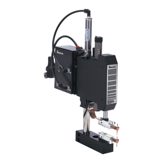
CHAPTER 1. SYSTEM DESCRIPTION Section II. System Components Typical TL-080B Weld Head Model TL-080B-A and TL-080B-F These are conventional, 20 lb. (89 N) capacity welding heads with offset, opposed electrodes. Both the pedestal mounting (post) and lower electrode assembly can be removed and replaced by custom fixtures. All air actuated heads in the TL-080B Series are available with either 24 volt, 50/60 Hz. -
Page 17: Model Tl-082B-A
CHAPTER 1. SYSTEM DESCRIPTION Model TL-082B-A This model is designed for automated and special applications requiring custom mounting configurations and custom lower electrode fixtures. Rugged in-line electrode design eliminates upper electrode deflection, the cause of wiping action, and permits a maximum welding force of 40 lbs. (178 N). The TL-082B-A is supplied with one ES0850, Glidcop, 1/4 in. -
Page 18: Model Tl-088B-A And Tl-088B-F
CHAPTER 1. SYSTEM DESCRIPTION Model TL-088B-A and TL-088B-F These are designed to function as either a series or a parallel weld head. The Electrode Holders are designed to hold eccentric electrodes which can be rotated, parallel to their length and adjusted with the electrode holders, so that the separation between the electrode faces is from 0.00 - 0.330 in. - Page 19 CHAPTER 1. SYSTEM DESCRIPTION Models TL-087B-SA and TL-084B-SA are similar to the Models TL-087B-A and TL-084B-A, respectively, except they are designed specifically for high-precision reflow soldering. The TL-087B-SA includes a Model I7TDSB 177 mounting block and the TL-084B-SA includes a Model 17TDMB256 mounting block.
-
Page 20: Section Iii. Welding Capabilities
CHAPTER 1. SYSTEM DESCRIPTION Section III. Welding Capabilities Series Welding In series welding applications, both electrodes contact the same surface of each workpiece. The weld current flows from one electrode through the workpiece to the other electrode. This technique is used to weld workpieces which have only one surface accessible. -
Page 21: Section Iv. Operating Controls
CHAPTER 1. SYSTEM DESCRIPTION Section IV. Operating Controls TL-080B-A - Air Actuation Specifications TL-080B-A, TL-086B-A, TL-082B-A, TL-083B-A, PARAMETER / MODEL TL-087B-A, TL-088B-A TL-084B-A, TL-089B-A Input Air Pressure - Nominal / Maximum 65/100 psi (448/690 kPa) 65/100 psi (448/690 kPa) Regulator Output - Maximum 65 psi (448 kPa) 65 psi (448 kPa) Cycle Rate (full strokes/sec) at Min. -
Page 22: Footswitches
CHAPTER 1. SYSTEM DESCRIPTION ELECTRICAL SPECIFICATIONS HALL EFFECT LIMIT SWITCH Open Collector - current sink Output Type 5 to 28 VDC Input Voltage (V Input Current 25mA maximum Output Voltage Drop 0.4 VDC maximum 300mA @ 0.4 VDC maximum Output Current 300mW maximum Power Dissipation Circuit Protection... -
Page 23: Chapter 2. Installation
Electrodes and weld cables are installed on the weld head. Mounting Posts TL-080B Weld Heads may be purchased with or without mounting hardware. Amada Weld Tech provides three types of mounting posts (and corresponding installation hardware) designed for different models: TL-080B THIN-LINE™... -
Page 24: Mounting Tube
CHAPTER 2: INSTALLATION Mounting Tube Smaller TL-080B Weld Heads are installed on short mounting tubes. These are factory installed and do not require any assembly by the user. Mounting tubes come in fixed lengths, the height of the weld head is not adjustable. Dual-Post This consists of two parallel posts connected at the top and bottom, leaving an open slot for the full length of the post. -
Page 25: Section Ii. Weld Head Installation
Make sure you have all necessary parts and mounting hardware. Use the shipping list as a reference. Verify that the paper mounting template corresponds to the model number of the weld head. If you do not have the correct template, contact Amada Weld Tech at the address shown in the front of the manual. - Page 26 CHAPTER 2: INSTALLATION If necessary, install the weld head mounting post to the baseplate. If you are using optics (microscope and/or illuminator), screw the optics mounting post to the optics baseplate (if not already installed). NOTE: Follow assembly instructions provided with the Optics. If necessary, drill holes in the Optics baseplate in order to accommodate the screws used to mount the weld head.
- Page 27 CHAPTER 2: INSTALLATION 7-A Install the weld head on the Dual-Post. A) Install the mounting screws and washers onto the mounting backplate. B) Place the weld head on the front of the mounting post, then insert the mounting screws through the slot in the back of the mounting post and screw them into the weld head. C) Adjust the weld head to the desired height, then tighten the mounting screws.
- Page 28 CHAPTER 2: INSTALLATION Install the weld head on the Channeled-Post. A) Install the weld head mounting plate onto the weld head using the screws as shown. B) Install the screws, washers, and T-nuts into the weld head mounting plate as shown. C) If necessary, remove the end cap from the mounting post to expose the channels in the mounting post.
- Page 29 CHAPTER 2: INSTALLATION TL-080B-F, TL-086B-F, and TL-087B-F Model CP Footpedal Installation Push down on top of weld head to extend end of pullrod. Secure Electrode Holders with string to hold in place. Position head (and optional baseplate) on bench as shown. Route footpedal cable up through bench (and baseplate).
- Page 30 CHAPTER 2: INSTALLATION Adjust footpedal so that the electrode holders move the distance required by the application. 10 Adjust the angle of the treadle so that it provides the electrode stroke necessary for the application and is comfortable for the operator. TL-084B-F, TL-088B-F, and TL-089B-F MSP Footpedal Installation TL-080B THIN-LINE™...
-
Page 31: Model Tl-082B-A Air Head Installation
CHAPTER 2: INSTALLATION Screw the head to the bench and Model MSP Footpedal using four (4) screws, washers and nuts supplied with the shipping kit. To adjust the height of the head, loosen two hex head cap screws on the mounting plate adapter, as illustrated, and slide Head up or down the mounting stand. - Page 32 CHAPTER 2: INSTALLATION Screw the air gauge assembly to the mounting plate, as illustrated, or in a location, which is as close as practical to the head. Use 0.25 in. (6.35 mm) outside diameter plastic hose, with a rated burst pressure of 250 psi (1,724 kPa), to connect the air pressure regulator to the fitting on the top of the air cylinder, as illustrated.
- Page 33 CHAPTER 2: INSTALLATION Dual-Air Installation NOTES: • Amada Weld Tech suggests that in-line lubricators only be used in automated applications, since excess oil can blow-by worn seals in the Air Cylinder and be deposited on the workpieces. • If an in-line lubricator is not used, then the air line should be removed from the top of the cylinder(s) once every 1 million cycles, and several drops of a light machine oil should be squirted into the top of the cylinder(s).
-
Page 34: Model Tl-080B-Ez, Tl-086B-Ez, And Tl-089B-Ez - Ez-Air Installation
CHAPTER 2: INSTALLATION Models TL-080B-EZ, TL-086B-EZ, and TL-089B - EZ EZ-AIR Installation These weld heads come equipped with EZ-AIR factory-installed. Installation consists of bolting the weld head to the work bench and connection to an air supply. To connect an air supply to the EZ-AIR input, follow the instructions in the separate EZ-Air manual. -
Page 35: Section Iii. Connect Weld Cables
Section III. Connect Weld Cables Weld Cables and Energy Losses All Amada Weld Tech weld heads are supplied with the correct weld cables to provide maximum weld energy. If you need to install longer cables, or replace damaged cables; •... -
Page 36: Connect Cables To Head
CHAPTER 2: INSTALLATION Connect Cables to Head Model TL-080B, TL-083B, and TL-084B: Connect one of the two cables supplied to the Power Bar. Model TL-082B-A: Only one cable is supplied, connect it to the Power Bar. Model TL-086B, TL-087B, TL-088B, and TL-089B: Connect one cable to each Power Bar. Place the washer, which is supplied, between the head of the Socket Head Screw and the Terminal on the Cable. -
Page 37: Section Iv. Install Electrodes For Welding
CHAPTER 2: INSTALLATION Section IV. Install Electrodes for Welding CAUTION Do not modify the electrode holders or attach additional mechanisms to the moving parts of the head. Doing so may hurt welding performance, damage the head, and void the warranty. Model TL-080B and TL-084B Loosen screws and insert electrodes. -
Page 38: Model Tl-088B And Tl-089B
CHAPTER 2: INSTALLATION Model TL-088B and TL-089B Insert electrodes into electrode holders. Lower the electrodes onto a flat workpiece. Align the electrodes so that they are parallel as well as perpendicular to the workpiece. Align the electrode tips. Rotate the electrodes to obtain the desired distance between the tips (gap). -
Page 39: Model Tl-086B - Unitip Electrodes
CHAPTER 2: INSTALLATION Tighten the electrode holder clamp screws. CAUTION: Do not over-torque the clamp screws. Doing so will deform the flexure, dramatically reducing its life. Open the electrodes to the desired operating gap by turning the gap adjustment knob counterclockwise. -
Page 40: Model Tl-087B - Unitip Electrodes
CHAPTER 2: INSTALLATION CAUTION: Unitips can be severely MAXIMUM UNITIP FORCE damaged by applying excessive bonding Max. Force Max. Force forces. The table on the right lists the Unitip Model (kgf) (oz) maximum operational force limits in both UTM111L 0.94 kilograms force (kgf) and ounces (oz). - Page 41 CHAPTER 2: INSTALLATION Insert the Unitip between the concave inner surfaces of the electrode arms. The Unitip should be flush with the top of the electrode holder. Rotate the Unitip so that the vertical line on the tip formed by the insulation layer is exactly between the two electrode arms when viewed from the front of the head.
-
Page 42: Section V. Install Thermodes For Reflow Soldering
CHAPTER 2: INSTALLATION Section V. Install Thermodes for Reflow Soldering Models TL-087B-SA and TL-084B-SA are similar to the Models TL-087B-A and TL-084B-A, respectively, except they are designed specifically for high-precision reflow soldering. The TL-087B-SA includes a Model I7TDSB 177 mounting block and the TL-084B-SA includes a Model 17TDMB256 mounting block. - Page 43 Model TL-087B - 17F Fold-Up, 17P Peg Tip, or 17SR Single Point Thermodes NOTE: Amada Weld Tech weld heads use two types of thermocouple connectors. Older models use telephone-type (or "Phone") plugs, newer models use Omega plugs. Both plugs work the same way.
- Page 44 CHAPTER 2: INSTALLATION NOTES: • The maximum width thermode which should be used with the TL-087B Head is the 17F1000, which is 1.0 in. (25.4 mm) wide. • Do not exceed a force of 60 oz. (16.68 N) on either the 17SF or 17SR series Single Point Fold-Up Thermodes.
-
Page 45: Section Vi. Install Optional Equipment
CHAPTER 2: INSTALLATION Section VI. Install Optional Equipment TL-088B and TL-089B - Install DFS/88 Series Firing Switch Junction Box If the TL-088B or TL-089B is to be used as a series type welding head, then connect both Firing Switch Cables to the DFS/88, which is supplied with the head. The DFS/88 connects the Force Firing Switches, which are located inside the heads, in series. -
Page 47: Chapter 3. Operating Instructions
CHAPTER 3 OPERATING INSTRUCTIONS Section I. Getting Started Installation Checklists INSTALLATION CHECKLIST FOR ALL HEADS Check that the cables are correctly attached at both ends. Verify that the Firing Switch Cable is attached to the welding power supply or control. Set the WELD/NO WELD Switch, located on the front of the welding ... -
Page 48: Welding Force Theory
Welding force (pressure) is a key variable in the resistance welding process. Excessive or insufficient welding force or pressure can cause a weak weld (see TL-088B-F and TL-089B-F). More information on Weld Force is available from Amada Weld Tech: A) Resistance Welding Troubleshooting Guide... - Page 49 CHAPTER 3: OPERATING INSTRUCTIONS WELDHEAD TROUBLESHOOTING GUIDE SYMPTOM PRIMARY CAUSE PRIORITY* SOLUTION Weldhead-Related Cause PROBLEM Increase current/energy in steps of 5-10% Insufficient Current/Energy Wrong Electrode Material Check Electrode/Material Selection Guide Use constant area electrodes or shape to suit Electrode Tip Shape application Replace or reshape electrodes or increase Mushroomed Electrodes...
-
Page 50: Reflow Soldering Force
In most cases capacitor discharge welds do not have a significant nugget. *** For non-Amada Weld Tech weld heads. A certain amount of experimentation is necessary to achieve the proper welding force setting for a specific application. The following are some general rules to make quality welds: Larger parts require higher force. -
Page 51: Section Ii. Model Tl-080B-A, Tl-082B-A, Tl-083B-A, Tl-084B-A, Tl-086B-A, And Tl-087B-A Standard Air-Actuated Head Setup
It should not move so rapidly that it slams against the upstop. If the application is a welding application, adjust the electrode spacing so that an Amada Weld Tech Force Gauge fits between the electrodes, as illustrated. TL-080B THIN-LINE™ WELD HEADS... - Page 52 If the firing switch closure is inaudible, it is easily detected by observing the firing switch indicator on the welding power supply or control. For older or non-Amada Weld Tech power supplies, an ohmmeter or continuity checker can be connected to the pins on the firing switch connector.
-
Page 53: Section Iii. Model Tl-080B-Ez And Tl-086B-Ez Ez-Air Air-Actuated Head Setup
Set heads with digital readouts to "100." If electrodes are being used, adjust the electrode spacing so that an Amada Weld Tech Force Gauge fits between the electrodes, as shown. - Page 54 CHAPTER 3: OPERATING INSTRUCTIONS After setting the required force, particularly in automated applications, remove the force adjustment knob by loosening the two set screws, which secure it to the shaft. Invert the knob and place it on the shaft. Be sure to insert the locking tab on the knob into the slot on the force tube.
-
Page 55: Section Iv. Model Tl-088B-A And Tl-089B-A Standard Air-Actuated Head Setup
TOP of the air cylinder, so that the upper arm moves up at a reasonable rate. It should not move so rapidly that it slams against the upstop. Place an Amada Weld Tech Force Gauge beneath the electrode, as shown. The force gauge must be supported on the bottom for proper indication of force. - Page 56 NOTE: If the firing switch closure is inaudible, it is easily detected by observing the firing switch indicator on the welding power supply or control. For older or non-Amada Weld Tech power supplies, an ohmmeter or continuity checker can be connected to the pins on the firing switch connector.
- Page 57 CHAPTER 3: OPERATING INSTRUCTIONS CAUTION: Do not attempt to use the downstop adjustments to limit the force which is applied to the workpiece. This will result in inconsistent welds. 15 Depress the footswitch. Adjust the downspeed air flow control valves so that the upper electrode arms descend slowly enough to prevent impact damage to the workpiece and electrodes.
-
Page 58: Section V. Model Tl-089B-Ez Ez-Air Air-Actuated Head Setup
Use the force adjustment knob to set the weld head force indicator to "4." The indicator is located on the front of the force tube just below the force adjustment knob. Place an Amada Weld Tech Force Gauge beneath the electrode, as shown. The force gauge must be supported on the bottom for proper indication of force. - Page 59 CHAPTER 3: OPERATING INSTRUCTIONS The force gauge will indicate the electrode force. Use the force adjustment knob to increase the indicated force if the initial force reading is less than the required force setting for the welding application. If the initial force reading is greater than the required force setting, decrease the indicated force.
-
Page 60: Section Vi. Model Tl-080B-F, Tl-084B-F, Tl-086B-F, And Tl-087B-F Manually-Actuated Head Setup
For older or non-Amada Weld Tech power supplies, an ohmmeter or continuity checker can be connected to the pins on the firing switch connector. - Page 61 CHAPTER 3: OPERATING INSTRUCTIONS Turn the downstop screw counter-clockwise to its fullest extension without actually disengaging it. This will allow maximum downward travel of the upper arm. The following downstop adjustment should be made only if the workpiece would be damaged if the upper arm travels too far.
-
Page 62: Section Vii. Model Tl-088B-F And Tl-089B-F Manually-Actuated Head Setup
For older or non-Amada Weld Tech power supplies, an ohmmeter or continuity checker can be connected to the pins on the firing switch connector. - Page 63 CHAPTER 3: OPERATING INSTRUCTIONS After setting the required force, remove the force adjustment knob by loosening the two set screws that secure it to the shaft. Invert the knob and place it on the shaft. Be sure to insert the locking tab on the knob into the slot on the force tube.
-
Page 65: Chapter 4. User Maintenance
CHAPTER 4 USER MAINTENANCE Section I. General Maintenance Inspection Clean all electrical connections every six months to minimize welding circuit resistance. Inspect all bearings and braces for excessive wear every three years and replace as necessary. Lubrication All bearing surfaces are designed for non-lubricated operation. Do not oil any bearings or sleeves except for the use of a dry lubricant on weld heads used in automated, air actuated systems. -
Page 66: Section Iii. Unitip Electrode Maintenance
CHAPTER 4: MAINTENANCE Section III. Unitip Electrode Maintenance To ensure the best possible welds, new Unitip electrodes must be cleaned (or "dressed") before they are first used. This ensures that the electrode tip is flat, which is necessary to make maximum contact with the workpiece surface. -
Page 67: Section Iv. Tare Spring Adjustment Model Tl-080B, Tl-086B, Tl-087B, And Tl-088B
CHAPTER 4: MAINTENANCE Section IV. Tare Spring Adjustment Model TL-080B, TL-086B, TL-087B, and TL-088B The tare spring adjustment compensates for the varying mass of different upper electrodes and adapters. Tare springs are not used in the model TL-082B, TL-083B, TL-084B or TL-089B. With the head in a vertical position and the upper arm and electrodes installed, set the force adjustment to minimum by turning the firing force adjustment knob fully counterclockwise. -
Page 69: Appendix A. Technical Specifications
APPENDIX A. Technical Specifications Low-Force Weld Heads: 0.25 to 20 lbs (2.2 to 89N) FEATURES TL-080B-F(1) TL-080B-A TL-086B-F(2) TL-086B-A(2) Actuation Manual Manual Weld Force Max. (lbs/N) 20 / 89 20 / 89 20 / 89 20 / 89 Min. (lbs/N) 0.5 / 2.2 0.5 / 2.2 0.25 / 1.1... - Page 70 APPENDIX A. TECHNICAL SPECIFICATIONS Low-Force Weld Heads: 0.25 to 20 lbs (2.2 to 89N) FEATURES TL-087B-F(1) TL-087B-A TL-088B-F TL-088B-A Actuation Manual Manual Weld Force Max. (lbs/N) 20 / 89 20 / 89 20 / 89 20 / 89 Min. (lbs/N) 0.25 / 1.1 0.5 / 2.2 0.5 / 2.2...
- Page 71 APPENDIX A. TECHNICAL SPECIFICATIONS Low-Force EZ-AIR Weld Heads: 0.25 to 20 lbs (2.2 to 89N) FEATURES TL-080B-EZ TL-086B-EZ TL-088B-EZ Actuation Weld Force Max. (lbs/N) 20 / 89 20 / 89 20 / 89 Min. (lbs/N) 1 / 4.4 1 / 4.4 1 / 4.4 Maximum Rating (KVA)
- Page 72 APPENDIX A. TECHNICAL SPECIFICATIONS High-Force Weld Heads: 4 to 40 Lbs (18 to 178N) FEATURES TL-082B-A TL-083B-A TL-084B-F Actuation Manual Weld Force Max. (lbs/N) 40 / 178 40 / 178 40 / 178 Min. (lbs/N) 6 / 27 6 / 27 4 / 18 Maximum Rating (kVA)
- Page 73 APPENDIX A. TECHNICAL SPECIFICATIONS High-Force Weld Heads: 4 to 40 lbs (18 to 178N) FEATURES TL-084B-A TL-089B-F TL-089B-A Actuation Manual Weld Force Max. (lbs/N) 40 / 178 40 / 178 40 / 178 Min. (lbs/N) 6 / 27 4 / 18 6 / 27 Maximum Rating (kVA)
- Page 74 APPENDIX A. TECHNICAL SPECIFICATIONS High-Force EZ-AIR Weld Heads: 4 to 40 Lbs (18 to 178N) FEATURES TL-083B-EZ TL-084B-EZ TL-089B-EZ Actuation Weld Force Max. (lbs/N) 40 / 178 40 / 178 40 / 178 Min. (lbs/N) 4 / 17.8 4 / 17.8 4 / 17.8 Maximum Rating (kVA)
- Page 75 APPENDIX A. TECHNICAL SPECIFICATIONS Model TL-087B-SA and TL-084B-SA Reflow Soldering Heads TL-087B-SA TL-084B-SA Feature (Low Force) (Medium Force) Actuation 20 / 88.96 40 / 177.92 Weld Force Maximum (lbs/N) Minimum (lbs/N) 2 / 8.9 5 / 22.2 Maximum Rating watt-second Electrode Stroke inch inch...
-
Page 77: Appendix Baccessories
APPENDIX B ACCESSORIES Accessories MODEL DESCRIPTION 80AK/24 Air Kit, 24V-50/60Hz. Includes Regulators, Gauges, Flow Controls, Cylinder, and Hardware. Air Kit, 115V-50/60Hz. Includes Regulators, Gauges, Flow Controls, Cylinder, and Hardware. 80AK/115 Converts Model TL-080B-F, TL-086B-F or TL-087B-F to Model TL-080B-A, TL-086B-A, TL-087B-A, respectively. Fiber Optic Illuminator System, 115V-50/60Hz. - Page 78 APPENDIX B. ACCESSORIES Accessories (Continued) MODEL DESCRIPTION Optic Mounting Assembly. Use with SZO and BPTL. Polishing Disks, 600 grit, 1.5 in. diameter, 50 pieces. Use to polish electrodes. Nikon SMZ 660 Stereo Zoom Microscope, 10x wide eyepieces, object lens 0.5X wide field, 195 SMZ-660 mm maximum working distance.
- Page 79 APPENDIX B. ACCESSORIES 1/8 Inch Electrodes EO0400 1/8 INCH DIAMETER OFFSET ELECTRODES Used with TL-080B Series Weld Heads Model Material EO0402 RWMA 2 EO0403 RWMA 3 EO0411 RWMA 11 INSERT EO0413 RWMA 13 INSERT EO0420 MOLY INSERT * Copper Alloy ** Refractory Alloy Insert ES0400 13 mm DIAMETER STRAIGHT ELECTRODES Used with TL-080B and TL-082B Series Weld Heads...
- Page 80 APPENDIX B. ACCESSORIES ES0800 6 mm DIAMETER STRAIGHT ELECTRODES Used with TL-082B, TL-083B, and TL-084B Series Weld Heads Model Material ES0802 RWMA 2 ES0803 RWMA 3 ES0850 GLIDCOP ES0811 RWMA 11 INSERT ES0813 RWMA 13 INSERT ES0820 MOLY INSERT 1/8 IN. DIAMETER ES0820A MOLY INSERT * Copper Alloy...
- Page 81 APPENDIX B. ACCESSORIES ETB2 AND ETB3 TABLE ELECTRODES Used with TL-080B and TL-086B Series Weld Heads Model ETB2 * 2 in. 1-3/4 in. 3/8 in. ETB4 TABLE ELECTRODE Used with TL-080B and TL-086B Series Weld Heads Model ETB4 3 in. 3-3/4 in.
- Page 82 APPENDIX B. ACCESSORIES UNITIP ELECTRODES FACE MAXIMUM MAXIMUM MODEL FORCE (oz) FORCE (kgf) Width Depth Length UTM111L 0.010 0.0009 0.001 0.025 0.94 UTM112L 0.010 0.010 0.002 0.025 0.94 UTM152L 0.010 0.005 0.002 0.025 0.47 UTM222L 0.018 0.020 0.002 0.050 3.75 UTM237L 0.030 0.020...
- Page 83 APPENDIX B. ACCESSORIES Electrode Holders MODEL HE87 Holders, Unitip/Thermode. Used on Model TL-087B-A and TL-087B-F weld heads. MODEL HE88 Electrode Holder Blocks. Holds 0.245 inch diameter electrodes. Adjusts Center- Center distance from 3/32 inch to 15/32 inch. Used on Model TL-088B weld heads. MODEL HE1208 Electrode Holder, 3/8 inch diameter x 2 inch long, for 1/4 inch diameter electrodes.
- Page 84 Unitip Adapter. Used on Model TL-086B weld heads. Thermode Blocks NOTE: are normally supplied with attached. You may order either Thermodes Type K Thermocouples instead. Contact Amada Weld Tech for details. Type E Type J Thermocouples TL-080B THIN-LINE™ WELD HEADS 990-121...
- Page 85 APPENDIX B. ACCESSORIES Thermodes 17TD THREE-DIMENSIONAL THERMODES CATALOG # TYPE MATERIAL SIZE (W x L) Used With TL-087B, TL-084B, and TL-180B-SA Reflow Heads (Fits Small, Medium, and Large Blocks) 17TDS1000/059 3-DIMENSIONAL Special alloy 0.059” x 1.0” (1.5 mm x 25.4 mm) 17TDS1000/079 3-DIMENSIONAL Special alloy...
- Page 86 APPENDIX B. ACCESSORIES 17B MULTIPLE LEAD BLADE THERMODE Used With TL-087B Reflow Heads Model Material Size 17BM070 Molybdenum 0.075 inch wide x 0.030 inch thick (1.905 mm x 0.762 mm) 17BM180 Molybdenum 0.220 inch wide x 0.030 inch thick (5.588 mm x 0.762 mm) 17BM360 Molybdenum 0.400 inch wide x 0.030 inch thick (10.16 mm x 0.762 mm)
- Page 87 APPENDIX B. ACCESSORIES 17P SINGLE POINT PEG TIP THERMODE Used With TL-087B Reflow Heads Model Material Size 17P20 Brazed Tungsten 0.020 inch diameter x 0.070 inch long (0.508 mm x 1.778 mm) 17P40 Brazed Tungsten 0.040 inch diameter x 0.070 inch long (1.016 mm x 1.778 mm) 17P50 Brazed Tungsten 0.050 inch diameter x 0.200 inch long (1.27 mm x 5.08 mm)
- Page 88 Size 16SR40 Molybdenum 0.040 inch wide x 0.010 inch thick (1.016 mm x 0.254 mm) NOTE: Amada Weld Tech Part Number 16SR40 replaces Amada Weld Tech Part Number 17SR40. 16 & 17M FINELINE MINIBAR THERMODE sed With TL-087B Reflow Heads...
- Page 89 APPENDIX B. ACCESSORIES 17F MULTIPLE LEAD FOLD-UP BAND THERMODE Used With TL-087B Reflow Heads Model Material Size 17F1000 Nichrome Alloy 0.1 inch wide x 0.075 inch thick (25.4 mm x 1.905 mm) 17F250 Nichrome Alloy 0.250 inch wide x 0.075 inch thick (6.35 mm x 1.905 mm) 17F350 Nichrome Alloy 0.350 inch wide x 0.075 inch thick (8.89 mm x 1.905 mm)
- Page 91 TEL. +1-626-303-5676 FAX, +1-626-358-8048 http://www.amadaweldtech.com AMADA WELD TECH CO., LTD. 200, Ishida, Isehara-shi, Kanagawa 259-1196, Japan AMADA WELD TECH KOREA CO., LTD. 28, Dongtanhana 1-gil, Hwaseong-si, Gyeonggi-do, 18423, Korea TEL. +82-31-8015-6810 FAX. +82-31-8003-5995 AMADA WELD TECH SHANGHAI CO., LTD. Unit 401, A206(C8), No. 77, Hongcao Road, Xuhui District, Shanghai, China TEL.
- Page 92 AMADA WELD TECH INC. 1820 South Myrtle Ave., Monrovia, CA 91016, U.S.A. TEL. +1-626-303-5676 FAX. +1-626-358-8048...
Need help?
Do you have a question about the Thin-Line TL-080B Series and is the answer not in the manual?
Questions and answers