Schmalz SCPMb Operating Instructions Manual
Mini compact ejector
Hide thumbs
Also See for SCPMb:
- Operating instructions manual (16 pages) ,
- Maintenance instruction (16 pages) ,
- Operating instructions manual (30 pages)

Related Manuals for Schmalz SCPMb


Summary of Contents for Schmalz SCPMb
- Page 1 Operating Instructions Mini Compact Ejector SCPMb WWW.SCHMALZ.COM EN-US · 30.30.01.02039 · 03 · 10/22...
- Page 2 Published by © J. Schmalz GmbH, 10/22 This document is protected by copyright. J. Schmalz GmbH retains the rights established thereby. Repro- duction of the contents, in full or in part, is only permitted within the limits of the legal provisions of copyright law. Any modifications to or abridgments of the document are prohibited without explicit writ- ten agreement from J. Schmalz GmbH.
-
Page 3: Table Of Contents
Contents Contents 1 Important Information ........................... 5 Note on Using this Document...................... 5 The technical documentation is part of the product ................ 5 Type Plate............................. 5 Symbol .............................. 6 2 Fundamental Safety Instructions........................ 7 Intended Use ............................ 7 Non-Intended Use.......................... 7 Personnel Qualifications........................ - Page 4 Contents 12 Spare and Wearing Parts.......................... 30 13 Accessories .............................. 31 14 Decommissioning and Recycling ......................... 32 14.1 Disposing of the Product........................ 32 14.2 Materials Used ........................... 32 15 Declarations of Conformity.......................... 33 15.1 EU Declaration of Conformity...................... 33 15.2 UKCA Conformity ..........................
-
Page 5: Important Information
ð Failure to follow the instructions in these Operating instructions may result in injuries! ð Schmalz is not liable for damage or malfunctions that result from failure to heed these instructions. If you still have questions after reading the technical documentation, contact Schmalz Service at: www.schmalz.com/services... -
Page 6: Symbol
1 Important Information 1.4 Symbol This symbol indicates useful and important information. ü This symbol represents a prerequisite that must be met prior to an operational step. 4 This symbol represents an action to be performed. ð This symbol represents the result of an action. Actions that consist of more than one step are numbered: 1. -
Page 7: Fundamental Safety Instructions
Intended use includes observing the technical data and the installation and operating instructions in this manual. 2.2 Non-Intended Use Schmalz accepts no liability for damage resulting from non-intended use of the mini valve terminal. In particular, the following types of use are considered non-intended use: •... -
Page 8: Residual Risks
2 Fundamental Safety Instructions 2.5 Residual Risks WARNING Noise pollution due to the escape of compressed air Hearing damage! 4 Wear ear protectors. 4 The ejector must only be operated with a silencer. WARNING Extraction of hazardous media, liquids or bulk material Personal injury or damage to property! 4 Do not extract harmful media such as dust, oil mists, vapors, aerosols etc. -
Page 9: Modifications To The Product
2 Fundamental Safety Instructions 2.6 Modifications to the Product Schmalz assumes no liability for consequences of modifications over which it has no control: 1. The product must be operated only in its original condition as delivered. 2. Use only original spare parts from Schmalz. -
Page 10: Product Description
The blow off function can be triggered by the ejector in two ways: • Externally controlled actuation of the blow off valve • Optional: external blow off 3.2 Ejector Designation The breakdown of the item designation (e.g. SCPMb 07 S01 NO AAE) is as follows: Property Variants Type SCPM Version... -
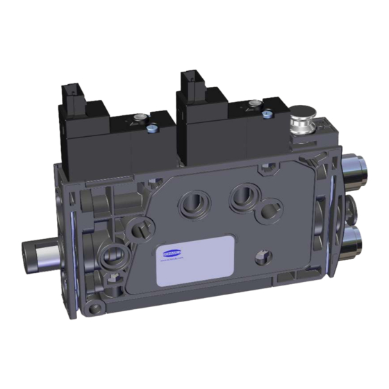
Page 11: Ejector Structure
3 Product Description 3.3 Ejector Structure Compressed air connector (marking 1) “Blow-off” solenoid valve Vacuum connection (marking 2) Optional: Compressed air connector for separate blow-off EB (marking 1A) Button for actuating the “suction” sole- Silencer (marking 3) noid valve manually “Suction” solenoid valve Valve screw for blow off flow rate Button for actuating the “blow off”... -
Page 12: Technical Data
— Typical current consump- Max. current consump- (at 24 V) tion tion SCPMb – xx – NC 50 mA 70 mA SCPMb – xx – NO 75 mA 115 mA The power supply must correspond to the regulations in accordance with EN60204 (protected extra-low voltage). - Page 13 4 Technical Data Type Nozzle 03 Nozzle 05 Nozzle 07 Nozzle 10 Nozzle 12 Rec. diameter of compressed air hose [mm] Rec. diameter of vacuum hose [mm] Weight [g] At optimum operating pressure (SCPM...03/05/07: 4 bar; SCPM...10/12: 4,5 bar) For max. length of 2 m 4.3.2 Dimensions 76.5 20.5...
- Page 14 4 Technical Data 4.3.4 Pneumatic circuit plans Key: Normally closed Normally open Compressed air connection Vacuum connection Exhaust outlet “Separate blow off” compressed air connec- tion NC-EB NO-EB 14 / 34 EN-US · 30.30.01.02039 · 03 · 10/22...
-
Page 15: Blow Off Modes
5 Blow off modes 5 Blow off modes 5.1 Externally Controlled Blow-Off The “blow off” valve is controlled directly by the “blow off” command. The ejector switches to blow off mode for as long as the “blow off” signal is present. The “blow off” signal is given priority over the “suction” signal. 5.2 Blow Off Using External Compressed Air The ejector is also available with an additional compressed air connector to supply the blow off pulse sep- arately (external blow off function = “EB”). -
Page 16: Checking The Delivery
1. Compare the entire delivery with the supplied delivery notes to make sure nothing is missing. 2. Damage caused by defective packaging or occurring in transit must be reported immediately to the carrier and J. Schmalz GmbH. 16 / 34 EN-US · 30.30.01.02039 · 03 · 10/22... -
Page 17: Installation
7 Installation 7 Installation 7.1 Installation Instructions CAUTION Improper installation or maintenance Personal injury or damage to property 4 During installation and maintenance, make sure that the product is disconnected and depressurized and that it cannot be switched on again without authorization. For safe installation, the following instructions must be observed: •... -
Page 18: Mounting On A Din Rail (Optional)
7 Installation Side mounting 4 There are two 4.3 mm through-holes for mounting the ejector. Use screws at least 20 mm in length. Use washers if you are using fastening screws M4 for the mounting process. The ejector must be attached using at least 2 screws;... - Page 19 7 Installation 2. Loosely screw the clamps onto the bracket in the correct position. 3. Attach the assembly with the bracket onto the DIN rail and press it onto it 4. Tighten the screw to tighten the clamp so that the assembly is fastened to the DIN rail.
-
Page 20: Pneumatic Connection
7 Installation 7.4 Pneumatic Connection CAUTION Compressed air or vacuum in direct contact with the eye Severe eye injury 4 Wear eye protection 4 Do not look into compressed air openings 4 Do not look into the silencer air stream 4 Do not look into vacuum openings, e.g. suction cups CAUTION Noise pollution due to incorrect installation of the pressure and vacuum connec- tions... - Page 21 7 Installation 7.4.2 Instructions for the Pneumatic Connection To ensure problem-free operation and a long service life for the mini compact ejector, always use ade- quately maintained compressed air and take the following requirements into account: • Use air or neutral gas in accordance with EN 983, filtered to 5 μm, unoiled •...
-
Page 22: Electrical Connection
7 Installation 4 Connect the compressed air hose for separate blow off (connector marked with 1A) and ad- just the blow off flow rate using the adjusting screw (2). 7.5 Electrical Connection NOTE Incorrect power supply Destruction of the integrated electronics 4 Operate the product using a power supply unit with protected extra-low voltage (PELV). - Page 23 7 Installation ü Provide connection cable (for example, 2x item no.: 21.04.06.00086) 4 Insert the connection cables into the electrical connections (1 and 2) until they click into place. EN-US · 30.30.01.02039 · 03 · 10/22 23 / 34...
-
Page 24: Operation
8 Operation 8 Operation 8.1 General Preparations WARNING Extraction of hazardous media, liquids or bulk material Personal injury or damage to property! 4 Do not extract harmful media such as dust, oil mists, vapors, aerosols etc. 4 Do not extract aggressive gases or media such as acids, acid fumes, bases, biocides, dis- infectants or detergents. -
Page 25: Help With Malfunctions
9 Help with Malfunctions 9 Help with Malfunctions Fault Possible cause Solution 4 Make sure device is properly con- Power supply disrupted Electrical connection nected to power 4 Check electrical connection Ejector does not re- No power supply spond 4 Check the compressed air supply No compressed air supply Vacuum level is not Silencer is dirty... -
Page 26: Maintenance
10 Maintenance 10 Maintenance 10.1 Safety Maintenance work may only be carried out by qualified personnel. WARNING Risk of injury due to incorrect maintenance or troubleshooting 4 Check the proper functioning of the product, especially the safety features, after every maintenance or troubleshooting operation. NOTE Incorrect maintenance work Damage to the ejector! - Page 27 10 Maintenance If the suction capacity decreases, replace the silencer insert: ü Deactivate the ejector and depressurize the pneumatic systems. 1. Place a small flat screwdriver on the ejector as shown and loosen the clamp. 2. Remove the clamp. 3. Then remove the silencer and silencer insert from the ejector.
- Page 28 10 Maintenance 5. Insert the new silencer insert into the housing and reinstall the silencer. 6. Mount the clamp in the correct position. ð The clamp is mounted flush with the un- derside of the ejector and the clamp legs both lie in the grooves.
-
Page 29: Warranty
11 Warranty 11 Warranty This system is guaranteed in accordance with our general terms of trade and delivery. The same applies to spare parts, provided that these are original parts supplied by us. We are not liable for any damage resulting from the use of non-original spare parts or accessories. The exclusive use of original spare parts is a prerequisite for the proper functioning of the ejector and for the validity of the warranty. -
Page 30: Spare And Wearing Parts
12 Spare and Wearing Parts 12 Spare and Wearing Parts Maintenance work may only be carried out by qualified personnel. WARNING Risk of injury due to incorrect maintenance or troubleshooting 4 Check the proper functioning of the product, especially the safety features, after every maintenance or troubleshooting operation. -
Page 31: Accessories
13 Accessories 13 Accessories Designation Part no. Note Connection cable, 21.04.06.00086 Connector 1: Vent Micro10 mm connector; Ca- ASK B-MIC10 3000 K-2P ble length: 3000 mm; Connector 2: Cable, 2- pin; Material: PUR cable Exhaust air set 10.02.02.06080 Plug-in screw union and thread adapter ABL-SET SCPMi/c/b Silencer for vacuum generator 10.02.02.05807... -
Page 32: Decommissioning And Recycling
14 Decommissioning and Recycling 14 Decommissioning and Recycling 14.1 Disposing of the Product 1. Dispose of the product properly after replacement or decommissioning. 2. Observe the country-specific guidelines and legal obligations for waste prevention and disposal. 14.2 Materials Used Component Material Housing PA6-GF Inner components Aluminum alloy, anodized aluminum alloy, stainless steel, POM Silencer insert... -
Page 33: Declarations Of Conformity
15 Declarations of Conformity 15 Declarations of Conformity 15.1 EU Declaration of Conformity The manufacturer Schmalz confirms that the product Ejector described in these operating instructions ful- fills the following applicable EU directives: 2006/42/EC Machinery Directive 2014/30/EU Electromagnetic Compatibility 2011/65/EU Directive on the restriction of the use of certain hazardous substances in... - Page 34 At Your Service Worldwide Vacuum Automation Handling Systems WWW.SCHMALZ.COM/AUTOMATION WWW.SCHMALZ.COM/AUTOMATION J. Schmalz GmbH Johannes-Schmalz-Str. 1 72293 Glatten, Germany T: +49 (0) 7443 2403-0 schmalz@schmalz.de WWW.SCHMALZ.COM...
Need help?
Do you have a question about the SCPMb and is the answer not in the manual?
Questions and answers