
Related Manuals for Schmalz SCPSi-L


Summary of Contents for Schmalz SCPSi-L
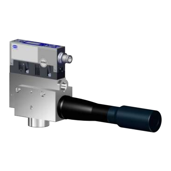
- Page 1 Compact Ejector SCPSi-L Operating Instructions WWW.SCHMALZ.COM EN-US · 30.30.01.02084 · 02 · 12/20...
- Page 2 Published by © J. Schmalz GmbH, 12/20 This document is protected by copyright. J. Schmalz GmbH retains the rights established thereby. Repro- duction of the contents, in full or in part, is only permitted within the limits of the legal provisions of copyright law. Any modifications to or abridgments of the document are prohibited without explicit writ- ten agreement from J. Schmalz GmbH.
-
Page 3: Table Of Contents
Contents Contents 1 Important Information ........................... 6 Note on Using this Document ...................... 6 The technical documentation is part of the product ................ 6 Type Plate ............................ 6 Warnings in This Document........................ 6 Symbol.............................. 7 2 Fundamental Safety Instructions........................ 8 Safety .............................. 8 Intended Use............................ - Page 4 Contents Vacuum Monitoring .......................... 25 Control Function.......................... 25 Blow off Functions .......................... 26 Monitoring the Supply Voltages ...................... 27 Evaluating the Inlet Pressure ...................... 27 Calibrating the Vacuum Sensor ...................... 27 7.10 Signal Output ............................ 28 7.11 Signal Type............................ 28 7.12 Control Concept for NO Ejectors ......................
- Page 5 Contents 12 Warnings and Errors ............................. 50 12.1 Error Messages in SIO Operation...................... 50 12.2 Warnings and Error Messages in IO-Link Mode ................ 50 12.3 System Status Light in IO-Link Mode .................... 51 13 Maintenance.............................. 52 13.1 Safety .............................. 52 13.2 Cleaning the Ejector.......................... 52 13.3 Removing the Ejector Module......................
-
Page 6: Important Information
ð Failure to follow the instructions in these Operating instructions may result in injuries! ð Schmalz is not liable for damage or malfunctions that result from failure to heed these instructions. If you still have questions after reading the technical documentation, contact Schmalz Service at: www.schmalz.com/services... -
Page 7: Symbol
Important Information 1.5 Symbol This symbol indicates useful and important information. ü This symbol represents a prerequisite that must be met prior to an operational step. 4 This symbol represents an action to be performed. ð This symbol represents the result of an action. Actions that consist of more than one step are numbered: 1. -
Page 8: Fundamental Safety Instructions
Fundamental Safety Instructions 2 Fundamental Safety Instructions 2.1 Safety The ejector emits noise due to its use of compressed air. WARNING Noise pollution due to the escape of compressed air Hearing damage! 4 Wear ear protectors. 4 The ejector must only be operated with a silencer. WARNING Uncontrolled movements of system components or falling of objects caused by in- correct activation and switching of the Ejector while persons are in the plant... -
Page 9: Non-Intended Use
2.5 Modifications to the Ejector Schmalz assumes no liability for consequences of modifications over which it has no control: 1. The ejector must be operated only in its original condition as delivered. 2. Use only original spare parts from Schmalz. -
Page 10: Product Description
Product Description 3 Product Description 3.1 Ejector Designation The breakdown of the item designation (e.g. SCPSi-L HF 3-16 NC RD M12-5 PNP) is as follows: Property Variants Type of ejector SCPSi-L, version with display SCPS-L, version with bar display Shape HF for “High Flow”... -
Page 11: Display And Operating Element In Detail
Product Description 3.3 Display and Operating Element in Detail Simple ejector operation is ensured with 3 buttons, the 3-digit display and 4 LEDs for status information. MENU BUTTON Display LED vacuum limit value H1 DOWN BUTTON UP BUTTON LED vacuum limit value H2 LED process state “suction”... - Page 12 Product Description Meaning of the Vacuum Limit Value LEDs The LEDs for the vacuum limit values H1 and H2 indicate the current level of the system vacuum relative to the configured limit values. Their display is independent of the switching function and assignment of the output, and independent of whether the condition monitoring function is active.
-
Page 13: Technical Data
Technical Data 4 Technical Data 4.1 Display Parameters Parameter Value Unit Comment Display Digit Red 7-segment LED display Resolution ±1 mbar — Accuracy ±3 % FS = 25° C, based on FS (full-scale) final value Linearity error ±1 — Offset error ±2 mbar After zero-point adjustment, without vacuum Temperature influ- ±3... -
Page 14: Factory Settings
Technical Data Parameter Symbol Limit values Unit Comment Current of signal input (PNP) — — — Current of signal input (NPN) — — — Reaction time of signal inputs — — — Reaction time of signal out- — Adjustable puts 1) The power supply must correspond to the regulations in accordance with EN60204 (protected extra-low voltage). -
Page 15: Performance Data
Technical Data 4.5 Performance Data Type SCPSi-L- SCPSi-L- SCPSi-L- SCPSi-L- SCPSi-L- SCPSi-L- 2-07 HV 2-09 HV 2-13 HF 2-16 HV 3-16 HV 3-20 HV Nozzle size [mm] Max. vacuum Suction rate [l/min] Max. blow off capacity min] Air consumption (suction) (l/min]... -
Page 16: Pneumatic Circuit Plans
Technical Data 4.7 Pneumatic Circuit Plans SCPSi-L...NO... SCPSi-L...NC... 16 / 72 EN-US · 30.30.01.02084 · 02 · 12/20... -
Page 17: Operating And Menu Concept
Operating and Menu Concept 5 Operating and Menu Concept The parameters can also be set using three buttons. The current system status and the settings are shown on a display. The unit is operated via three buttons on the foil keypad. Settings are configured using software menus. The operating structure is divided into settings in the main menu and configuration menu. -
Page 18: Main Menu
Operating and Menu Concept In IO-Link mode, you can also press the button again to view the IO-Link Standard (1.0, 1.1) that is cur- rently in use. After 3 seconds, the screen returns to the vacuum display. 5.3 Main Menu All the settings for standard ejector applications can be configured and read through the main menu: 1. - Page 19 Operating and Menu Concept Display Parameter Possible settings Explanation code Max. permissi- Configurable be- Permissible evacuation time; evaluation in IO- ble evacuation tween 0.01 and Link only time 9.99 s in 0.01 incre- ments No monitoring Menu item only displayed when ctr = On5 Max.
-
Page 20: System Menu
Operating and Menu Concept 5.5 System Menu A special menu is available for reading out system data such as counters, the software version, part num- bers and serial numbers. 1. Open the system menu by simultaneously pressing the buttons for more than 3 seconds. ð... -
Page 21: Operating Modes
Operating Modes 6 Operating Modes All the ejectors in the SCPSi-L series can be operated in two operating modes: • Via direct connection to inputs and outputs (standard I/O = SIO) or • Connection via a communication line (IO-Link) By default, the ejector always runs in SIO mode, but it can be switched in and out of IO-Link mode by an IO-Link master at any time. -
Page 22: Process Data
Operating Modes 6.2.1 Process Data The cyclical process data is used to control the ejectors and receive current information reported from the ejector. There is a difference between the input data (Process Data In) and the controlling output data (Process Data Out). The input data Process Data In is used to report the following information cyclically: •... -
Page 23: General Description Of Functions
General Description of Functions 7 General Description of Functions 7.1 Picking up the Workpiece (Vacuum Generation) The ejector is designed for handling and holding workpieces by means of a vacuum in combination with suction systems. The vacuum is generated in a nozzle according to the Venturi principle, using suction generated by the flow of accelerated compressed air. -
Page 24: Operating Modes
General Description of Functions • Externally time-controlled blow off The current process state is indicated by the LED status indicators. During blow off, [-FF] is shown on the display. 7.3 Operating Modes The ejector can be operated in four operating modes: •... -
Page 25: Vacuum Monitoring
General Description of Functions Activating the Operating Mode Press and hold the button for more than 3 seconds. An M appears on the display while you do The current process state is retained. Manual suction button activates “suction” on the ejector. Press the button to exit the “suction”... -
Page 26: Blow Off Functions
General Description of Functions Operating mode Explanation No control/continuous suction, H1 The ejector produces continuous suction with maximum in hysteresis mode power. This setting is recommended for very porous workpieces, which would otherwise cause vacuum gener- [ctr] => [oFF] ation to switch on and off continuously due to the high rate of leakage. -
Page 27: Monitoring The Supply Voltages
General Description of Functions Description Explanation The blow off signal overrides the suction signal, even if the specified blow off time is very long. The length of the blow off time [tbL] is set in the main menu. This menu item is suppressed in operating mode [-E-]. -
Page 28: Signal Output
General Description of Functions When the permissible limit is exceeded by ±3%, error code E03 will appear on the display. 7.10 Signal Output The ejector has a signal output. The signal output can be configured using the corresponding menu item. The signal output OUT can be switched between [no] (normally open) and [nc] (normally closed) con- tact. -
Page 29: Control Concept For Nc Ejectors
General Description of Functions 7.13 Control Concept for NC Ejectors “Suction” [IN1] “Blow off” [IN2] “Suction” state 0 bar “Blow off” state 0 bar 7.14 Vacuum unit You can choose between the following three units for the unit of the displayed vacuum level under the [uni] menu item in the configuration menu or via IO-Link. -
Page 30: Write Protection
General Description of Functions If you activate ECO mode using IO-Link, the display will immediately enter energy-saving mode. 7.17 Write Protection A PIN can be used to prevent the parameters from being changed via the user menu. The current settings are still displayed. The PIN is set to 000 on delivery. meaning access to the parame- ters is not locked. -
Page 31: Counters
General Description of Functions 4. Press the for more than 3 seconds. ð The ejector is reset to the factory settings. ð The display flashes for a number of seconds and then returns to display mode. The function for resetting factory settings does not affect the following elements: •... -
Page 32: Displaying The Serial Number
General Description of Functions 2. You can press the button to display the remaining digits of the part number. The decimal points shown are part of the part number. The part number consists of 4 number blocks with a total of 11 digits. Displayed section 02. -
Page 33: Energy And Process Control (Epc)
General Description of Functions Any operation being performed in the menu will be interrupted if an error occurs. The error code can also be opened as a parameter using IO-Link. 7.25 Energy and Process Control (EPC) In IO-Link mode, the energy and process control (EPC) function is available. It is subdivided into three modules: •... - Page 34 General Description of Functions This warning is available at the end of the current suction phase and remains active until the next suction cycle. Measuring and monitoring the evacuation times: t0 is the time from the beginning of a suction cycle to when the vacuum limit value H2 is reached (in ms). t1 is the time from when the vacuum limit value H2 is reached to when the vacuum limit value H1 is reached (in ms).
-
Page 35: Energy Monitoring (Em)
General Description of Functions Leakage L < permitted value -L- Leakage L > permitted value -L- If the leakage is lower than the set value, the If the leakage is higher than the value, the vacuum continues to fall until it reaches the ejector readjusts immediately. -
Page 36: Predictive Maintenance (Pm)
General Description of Functions An absolute air consumption measurement can be made only using a pressure value supplied externally via IO-Link. The measured value for the absolute air consumption (air consumption per cycle) is reset at the start of suction and then continuously updated during the cycle. It can continue to change until after the end of blow-off. -
Page 37: Diagnostic Buffer
General Description of Functions 7.25.4 Diagnostic Buffer The condition monitoring warnings described above and the general error messages from the device are saved in an integrated diagnostic buffer. The content of this memory is made up of the last 38 events, starting with the most recent, and can be read out via an IO-Link parameter. - Page 38 General Description of Functions 1. Start with EPC-Select = 00. 2. Create the selection for the next value pair you require (e.g. EPC-Select = 01) 3. Wait until the EPC-Select-Acknowledge bit changes from 0 to 1. ð The transmitted values correspond to the selection you have created, and can be adopted by the control system.
-
Page 39: Transport And Storage
1. Compare the entire delivery with the supplied delivery notes to make sure nothing is missing. 2. Damage caused by defective packaging or occurring in transit must be reported immediately to the carrier and J. Schmalz GmbH. EN-US · 30.30.01.02084 · 02 · 12/20... -
Page 40: Installation
Installation 9 Installation 9.1 Installation Instructions CAUTION Improper installation or maintenance Personal injury or damage to property 4 During installation and maintenance, make sure that the ejector is disconnected and depressurized and that it cannot be switched on again without authorization. For safe installation, the following instructions must be observed: 1. -
Page 41: Pneumatic Connection
Installation 9.3 Pneumatic Connection CAUTION Compressed air or vacuum in direct contact with the eye Severe eye injury 4 Wear eye protection 4 Do not look into compressed air openings 4 Do not look into the silencer air stream 4 Do not look into vacuum openings, e.g. suction cups CAUTION Noise pollution due to incorrect installation of the pressure and vacuum connec- tions... -
Page 42: Instructions For The Pneumatic Connection
The following table shows the recommended line cross-sections (internal diameter): Performance class Line cross-section (internal diameter) in mm pressure side Vacuum side SCPSi-L 2-07 SCPSi-L 2-09 SCPSi-L 2-13 SCPSi-L 2-16 SCPSi-L 3-16 SCPSi-L 3-20 Based on a maximum hose length of 2 m. - Page 43 Installation NOTE Incorrect power supply Destruction of the integrated electronics 4 Operate the product using a power supply unit with protected extra-low voltage (PELV). 4 The system must incorporate safe electrical cut-off of the power supply in compliance with EN60204. 4 Do not connect or disconnect the connector under tension and/or when voltage is ap- plied.
-
Page 44: Pin Assignment
Gray — — 1) When using Schmalz connection cable part no. 21.04.05.00080 9.5 Start of Operations A typical handling cycle is divided into the following three phases: pickup, blowoff and idle. To check whether sufficient vacuum has built up, the limit value H2 is monitored by an integrated vacuum sensor during suction and output to the higher-level controller via OUT. -
Page 45: Operation
Operation 10 Operation 10.1 Safety Instructions for Operation CAUTION Depending on the purity of the ambient air, the exhaust air can contain particles, which escape from the exhaust air outlet at high speed. Eye injuries 4 Do not look into the exhaust air flow 4 Wear eye protection CAUTION When the system is started in automatic operation, components move without ad-... -
Page 46: Typical Suction Cycles
Operation 10.3 Typical Suction Cycles The diagrams below show some typical vacuum processes during a suction cycle. The diagrams also indi- cate the times at which EPC measured values are updated. Handling cycle with dynamic pressure measurement and average leakage: Typical suction cycle SUCTION BLOW NEUTRAL... - Page 47 Operation Handling cycle with dynamic pressure measurement and excessive leakage: Typical suction cycle SUCTION BLOW NEUTRAL SUCTION Vacuum Condition monitoring Evacuation time t0 Evacuation time t1 Dynamic pressure Leakage Air consumption El. energy consumption Handling cycle with leakage > L and readjustment: Typical suction cycle SUCTION BLOW...
- Page 48 Operation Handling cycle with very high leakage (H1 is not reached): Typical suction cycle SUCTION BLOW NEUTRAL SUCTION Vacuum Condition monitoring Evacuation time t0 Evacuation time t1 Dynamic pressure Leakage Air consumption El. energy consumption Handling cycle with excessive evacuation time t1: Typical suction cycle SUCTION BLOW...
-
Page 49: Troubleshooting
4 Check the compressed air No compressed air supply supply. 4 Check the ejector and Ejector is faulty. contact Schmalz Service if necessary. 4 Replace screen Vacuum level is not reached Press-in screen in contami- or vacuum is created too... -
Page 50: Warnings And Errors
Warnings and Errors 12 Warnings and Errors 12.1 Error Messages in SIO Operation When a known error occurs, this is reported in the form of an error number. In SIO mode, error messages are shown on the display. An “E” followed by the error number appears on the display. The following table shows all the error codes: Code dis- Explanation... -
Page 51: System Status Light In Io-Link Mode
Warnings and Errors Any condition monitoring events that occur during the suction cycle cause the system status indicator light to immediately switch from green to yellow/orange. The event that caused this switch can be seen in the “Condition monitoring” IO-Link parameter. The table below explains the coding of the condition monitoring warnings: Event Update... -
Page 52: Maintenance
Maintenance 13 Maintenance 13.1 Safety Maintenance work may only be carried out by qualified personnel. 4 Create atmospheric pressure in the ejector's compressed air circuit before working on the system! WARNING Risk of injury due to incorrect maintenance or troubleshooting 4 Check the proper functioning of the product, especially the safety features, after every maintenance or troubleshooting operation. -
Page 53: Opening And Cleaning The Ejector Module
4 If the performance drops noticeably, clean the sieve with a paintbrush. If it is heavily soiled, you can send the ejector to Schmalz for repair (soiled sieves are replaced) subject to a fee. - Page 54 Maintenance Use the Parameterization server function of the IO-Link master to ensure that no data is lost when switching the device. 54 / 72 EN-US · 30.30.01.02084 · 02 · 12/20...
-
Page 55: Warranty
Warranty 14 Warranty This system is guaranteed in accordance with our general terms of trade and delivery. The same applies to spare parts, provided that these are original parts supplied by us. We are not liable for any damage resulting from the use of non-original spare parts or accessories. The exclusive use of original spare parts is a prerequisite for the proper functioning of the ejector and for the validity of the warranty. -
Page 56: Spare And Wearing Parts, Accessories
Spare and Wearing Parts, Accessories 15 Spare and Wearing Parts, Accessories 15.1 Spare and wearing parts Maintenance work may only be carried out by qualified personnel. 4 WARNING! Risk of injury due to improper maintenance! After performing any maintenance or re- pair work, check that the system is functioning correctly, particularly the safety features. NOTE Incorrect maintenance work Damage to the ejector! - Page 57 Spare and Wearing Parts, Accessories Part no. Designation Note 10.07.01.00126 VFT, 1/2" internal Vacuum cup filter, replaceable filter thread, 100 EN-US · 30.30.01.02084 · 02 · 12/20 57 / 72...
-
Page 58: Decommissioning And Recycling
Decommissioning and Recycling 16 Decommissioning and Recycling 16.1 Disposing of the Ejector 1. Dispose of the product properly after replacement or decommissioning. 2. Observe the country-specific guidelines and legal obligations for waste prevention and disposal. 16.2 Materials Used Component Material Housing PA6-GF, PC-ABS, aluminum alloy Inner components Aluminum alloy, anodized aluminum alloy, brass, galvanized steel, stainless- steel, PU, POM... -
Page 59: Attachment
Attachment 17 Attachment See also 2 SCPSi_V2 Data Dictionary 21.10.01.00065_02 2014-08-29.pdf [} 61] 17.1 Overview of the Display Codes Code Parameter Comment Limit value H1 Switch-off value for air-saving function/control Hysteresis value h1 Hysteresis of control Limit value H2 Switch-on value of the “Part Present” signal output (when the NO output is configured) Hysteresis value h2 Hysteresis of “Part Present”... -
Page 60: Ec Conformity
The buttons and menus are unlocked. Reset All adjustable values are reset to the factory settings. 17.2 EC Conformity EU Conformity Declaration The manufacturer Schmalz confirms that the product Ejector described in these Operating instructions ful- fills the following applicable EU directives: 2014/30/EU Electromagnetic Compatibility 2011/65/EU... - Page 61 IO-Link Data Dictionary SCPSi series 21.10.01.00065/02 29.08.2014 J. Schmalz GmbH Aacher Straße 29, D 72293 Glatten Tel.: +49(0)7443/2403-0 Fax: +49(0)7443/2403-259 info@schmalz.de IO-Link Implementation IO-Link Version 1.1 IO-Link Version 1.0 (legacy mode) Vendor ID 234 (0x00EA) 234 (0x00EA) Device ID 100243 (0x018793)
- Page 62 IO-Link Data Dictionary SCPSi series 21.10.01.00065/02 29.08.2014 J. Schmalz GmbH Aacher Straße 29, D 72293 Glatten Tel.: +49(0)7443/2403-0 Fax: +49(0)7443/2403-259 info@schmalz.de Process Data Out Name Bits Access Availability Remark Vacuum IO-Link V1.1, V1.0 Vacuum on/off Blow-off IO-Link V1.1, V1.0 Activate Blow-off...
- Page 63 IO-Link Data Dictionary SCPSi series 21.10.01.00065/02 29.08.2014 J. Schmalz GmbH Aacher Straße 29, D 72293 Glatten Tel.: +49(0)7443/2403-0 Fax: +49(0)7443/2403-259 info@schmalz.de 0x0012 Product name 8 bytes SCPSi_V2 General product name Product text 0x0014 30 bytes SCPSi 00 G2 NC M12-5 Order-Code...
- Page 64 IO-Link Data Dictionary SCPSi series 21.10.01.00065/02 29.08.2014 J. Schmalz GmbH Aacher Straße 29, D 72293 Glatten Tel.: +49(0)7443/2403-0 Fax: +49(0)7443/2403-259 info@schmalz.de 0 = off 0x004E dCS Disable continuous suction 1 byte 0 - 1 1 = on 0x0064 H-1 Setpoint H1 2 bytes 998 >= H1 >= (H2+h1)
- Page 65 IO-Link Data Dictionary SCPSi series 21.10.01.00065/02 29.08.2014 J. Schmalz GmbH Aacher Straße 29, D 72293 Glatten Tel.: +49(0)7443/2403-0 Fax: +49(0)7443/2403-259 info@schmalz.de 0x00D0 Permissible leakage rate 2 bytes 1 - 999 Production Setup - Profile P3 Profile P-3 0x00DC Air saving function...
- Page 66 IO-Link Data Dictionary SCPSi series 21.10.01.00065/02 29.08.2014 J. Schmalz GmbH Aacher Straße 29, D 72293 Glatten Tel.: +49(0)7443/2403-0 Fax: +49(0)7443/2403-259 info@schmalz.de Diagnosis Error 0x0082 Exx Active error code 1 byte 1-99 = Error code displayed by the device ...
- Page 67 IO-Link Data Dictionary SCPSi series 21.10.01.00065/02 29.08.2014 J. Schmalz GmbH Aacher Straße 29, D 72293 Glatten Tel.: +49(0)7443/2403-0 Fax: +49(0)7443/2403-259 info@schmalz.de Predictive Maintenance [PM] Leakage rate 0x00A0 2 bytes Leakage of last suction cycle (unit: 1 mbar/sec) 0x00A1 Free-flow vacuum...
- Page 68 IO-Link Data Dictionary SCPSi series 21.10.01.00065/02 29.08.2014 J. Schmalz GmbH Aacher Straße 29, D 72293 Glatten Tel.: +49(0)7443/2403-0 Fax: +49(0)7443/2403-259 info@schmalz.de Availability of EPC data during suction cycle J. Schmalz GmbH 8 of 11 SCPSi Data Dictionary...
- Page 69 IO-Link Data Dictionary SCPSi series 21.10.01.00065/02 29.08.2014 J. Schmalz GmbH Aacher Straße 29, D 72293 Glatten Tel.: +49(0)7443/2403-0 Fax: +49(0)7443/2403-259 info@schmalz.de Diagnostic Buffer - Details Data Format of Single Entry (ISDU 132) Bytes 0…1 Bytes 2…5 Remark Diagnostic-Type (MSB first)
- Page 70 IO-Link Data Dictionary SCPSi series 21.10.01.00065/02 29.08.2014 J. Schmalz GmbH Aacher Straße 29, D 72293 Glatten Tel.: +49(0)7443/2403-0 Fax: +49(0)7443/2403-259 info@schmalz.de 0x0208 Error E08 disappeared: IO-Link communication interrupted 0x120C Error E12 appeared: Short-circuit at OUT2 0x020C Error E12 disappeared: Short-circuit at OUT2...
- Page 71 IO-Link Data Dictionary SCPSi series 21.10.01.00065/02 29.08.2014 J. Schmalz GmbH Aacher Straße 29, D 72293 Glatten Tel.: +49(0)7443/2403-0 Fax: +49(0)7443/2403-259 info@schmalz.de EPC Data Buffer - Details Data Format of Single Entry (ISDU 134) Bytes 0…1 Bytes 2…3 Bytes 4…5 Bytes 6…9...
Need help?
Do you have a question about the SCPSi-L and is the answer not in the manual?
Questions and answers