Schmalz SCPMc Operating Instructions Manual
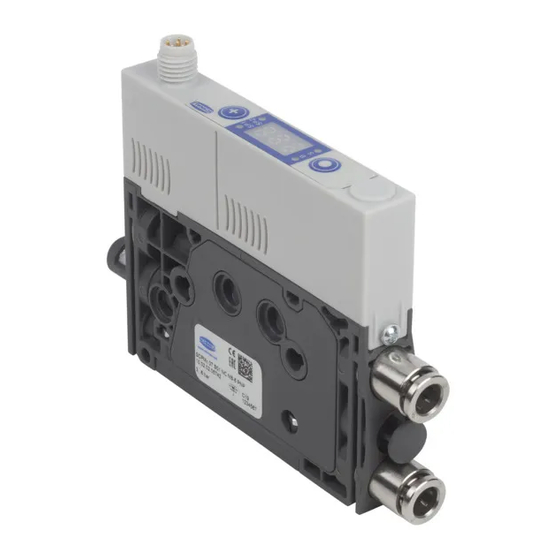
Mini compact ejector
Hide thumbs
Also See for SCPMc:
- Operating instructions manual (52 pages) ,
- Operating instructions manual (16 pages) ,
- Maintenance instruction (16 pages)

Related Manuals for Schmalz SCPMc


Summary of Contents for Schmalz SCPMc
- Page 1 Operating Instructions Mini Compact Ejector SCPMc WWW.SCHMALZ.COM EN-US · 30.30.01.01963 · 04 · 06/23...
- Page 2 Published by © J. Schmalz GmbH, 06/23 This document is protected by copyright. J. Schmalz GmbH retains the rights established thereby. Repro- duction of the contents, in full or in part, is only permitted within the limits of the legal provisions of copyright law. Any modifications to or abridgments of the document are prohibited without explicit writ- ten agreement from J. Schmalz GmbH.
-
Page 3: Table Of Contents
Contents Contents 1 Important Information ........................... 5 Note on Using this Document...................... 5 The technical documentation is part of the product ................ 5 Type Plate............................. 5 Symbols.............................. 6 2 Fundamental Safety Instructions........................ 7 Intended Use ............................ 7 Non-Intended Use.......................... 7 Personnel Qualifications........................ - Page 4 Contents 9 Operation .............................. 35 General Preparations......................... 35 Changing the Blow-Off Flow Rate on the Ejector ................ 35 10 Troubleshooting ............................ 36 10.1 Help with Malfunctions........................ 36 10.2 Error messages ........................... 37 11 Maintenance .............................. 38 11.1 Safety.............................. 38 11.2 Cleaning the Ejector ..........................
-
Page 5: Important Information
ð Failure to follow the instructions in these Operating instructions may result in injuries! ð Schmalz is not liable for damage or malfunctions that result from failure to heed these instructions. If you still have questions after reading the technical documentation, contact Schmalz Service at: www.schmalz.com/services... -
Page 6: Symbols
1 Important Information 1.4 Symbols This symbol indicates useful and important information. ü This symbol represents a prerequisite that must be met before an action is performed. 4 This symbol represents an action to be performed. ð This symbol represents the result of an action. Actions that consist of more than one step are numbered: 1. -
Page 7: Fundamental Safety Instructions
Intended use includes observing the technical data and the installation and operating instructions in this manual. 2.2 Non-Intended Use Schmalz accepts no liability for damage resulting from non-intended use of the mini valve terminal. In particular, the following types of use are considered non-intended use: •... -
Page 8: Modifications To The Product
2 Fundamental Safety Instructions 2.5 Modifications to the Product Schmalz assumes no liability for consequences of modifications over which it has no control: 1. The product must be operated only in its original condition as delivered. 2. Use only original spare parts from Schmalz. -
Page 9: Product Description
3 Product Description 3 Product Description 3.1 Product Name The breakdown of the item designation (e.g. SCPMc 10 S04 NC M8-6 PNP BLT) is as follows: Property Variants Type SCPM (mini compact ejector) Version Basic: b Controlled: c Intelligent: i Nozzle size 0.3, 0.5, 0.7, 1.0 and 1.2 mm, and EV for External Vacuum... - Page 10 3 Product Description 3.3 Controls and Displays in Detail The mini compact ejector is fitted with the following elements to ensure simple operation: • Two buttons on the foil keypad • The three-digit display • Four light-emitting diodes (LEDs) as status indicators MENU BUTTON PLUS BUTTON LED B for blow off state...
- Page 11 3 Product Description The display is independent of the switching function and the assignment of the output. The table below explains the meanings of the LEDs: Item Limit value LEDs Status 4 and 6 LEDs are both off Rising vacuum: Vacuum < SP2 Falling vacuum: Vacuum <...
-
Page 12: Technical Data
4 Technical Data 4 Technical Data 4.1 Display Parameters Parameter Value Comment Display 3-digit Red 7-segment LED display Resolution ±1 mbar — Accuracy ±3% FS = 25° C, based on FS (full-scale) final value Display refresh rate 5 1/s Only affects the 7-segment display Idle time before the menu is ex- 1 min The display mode is accessed automatically when no ited... -
Page 13: Mechanical Data
Polarity reversal protec- tion Current consumption — Typical current consump- Max. current consump- (at 24 V) tion tion SCPMc – xx – NC 50 mA 70 mA SCPMc – xx – NO 75 mA 115 mA EN-US · 30.30.01.01963 · 04 · 06/23 13 / 48... - Page 14 4 Technical Data The power supply must correspond to the regulations in accordance with EN60204 (protected extra-low voltage). 4.3.3 Dimensions M8x1 76.5 65.3 11.4 20.5 73.9 24.95 male thread 17.5 Depends on the specific ejector, (> See ch. 3.1 12.5 Product Name, p. All specifications are in mm 4.3.4 Maximum Torque Connection...
- Page 15 4 Technical Data Code Parameter Value of the factory setting Activated = on Control Evacuation time 0 s Leakage value 0 mbar/s Vacuum unit in mbar = bar Vacuum unit 4.3.6 Pneumatic circuit plans Legend: Normally closed Normally open Compressed air connection Vacuum connection Exhaust outlet “Separate blow off”...
- Page 16 4 Technical Data NC-EB NO-EB 16 / 48 EN-US · 30.30.01.01963 · 04 · 06/23...
-
Page 17: Operating And Menu Concept
5 Operating and Menu Concept 5 Operating and Menu Concept The mini compact ejector is operated using two buttons on the foil keypad: MENU BUTTON PLUS BUTTON The following information can be shown on the display: • The current vacuum measurement value •... -
Page 18: Extended Functions Menu (Ef)
5 Operating and Menu Concept 5.1.2 Displaying the Basic Settings (Slide Show) When you press the MENU button from the home screen, the following parameters are automatically shown one after the other on the display (slide show): • The vacuum unit •... -
Page 19: Info Menu [Inf]
5 Operating and Menu Concept Display Parameter Possible settings Explanation code Vacuum value in inch of mercury [inHg] Vacuum value in pound-force per square inch [psi] Reset The values remain unchanged Reset parameter values to factory settings 5.2.2 Changing parameters in the Extended Functions menu Depending on the parameter, there are two different methods for entering values in the EF menu. - Page 20 5 Operating and Menu Concept Display code Parameter Explanation Counter 1 Counter for suction cycles (suction signal input) Counter 2 Counter for valve switching cycles Software Display firmware revision Part number Display the part number Serial number Display the serial number Information about the production period 5.3.2 How Data is Displayed in the Info Menu Counter values...
-
Page 21: Description Of Functions
6 Description of Functions 6 Description of Functions 6.1 Applying Suction to the Workpiece/Part (Vacuum Generation) The ejector is designed for handling and holding workpieces by means of a vacuum in combination with suction systems. The vacuum is generated in a nozzle according to the venturi principle, using suction generated by the flow of accelerated compressed air. -
Page 22: Monitoring The System Vacuum And Defining Limit Values
6 Description of Functions During blow off, [-FF] is shown on the display. The ejector provides two blow off modes for selection: • Externally controlled blow off • Internally time-controlled blow off 6.3 Monitoring the system vacuum and defining limit values The ejector has integrated sensors for measuring the vacuum. -
Page 23: Blow Off Modes
6 Description of Functions 6.5.2 Control The ejector switches off vacuum generation when the switching point SP1 is reached and switches it back on when the vacuum falls below the reset point rP1. The switching point evaluation for SP1 follows the control function. -
Page 24: Counters
6 Description of Functions This function is executed using the parameter [rE5] in the EF menu. The factory settings for the ejector are listed in the Technical Data section. WARNING By activating/deactivating the product, output signals lead to an action in the pro- duction process! Personal injury 4 Avoid possible danger zone. -
Page 25: Displaying The Part Number
6 Description of Functions Displayed section 0. 4 8 61. 8 Digit block The current counter total in this example is 48 618 593. Counter levels that cannot be deleted are saved only in increments of 1000. That means that when the operating voltage is switched off, up to 999 counter steps are lost. - Page 26 6 Description of Functions 4 To exit the Info menu, press the MENU button. 26 / 48 EN-US · 30.30.01.01963 · 04 · 06/23...
-
Page 27: Checking The Delivery
1. Compare the entire delivery with the supplied delivery notes to make sure nothing is missing. 2. Damage caused by defective packaging or occurring in transit must be reported immediately to the carrier and J. Schmalz GmbH. EN-US · 30.30.01.01963 · 04 · 06/23... -
Page 28: Installation
8 Installation 8 Installation 8.1 Installation Instructions CAUTION Improper installation or maintenance Personal injury or damage to property 4 During installation and maintenance, make sure that the product is disconnected and depressurized and that it cannot be switched on again without authorization. For safe installation, the following instructions must be observed: •... -
Page 29: Mounting On A Din Rail (Optional)
8 Installation 8.2.1 Mounting with Two Screws 4 There are two 4.3 mm through-holes for mounting the mini compact ejector. Use screws at least 20 mm in length. Use washers if you are using fastening screws M4 for the mounting process. The mini compact ejector must be fastened in place using at least two screws. -
Page 30: Pneumatic Connection
8 Installation 3. Attach the assembly with the bracket onto the DIN rail and press it onto it 4. Tighten the screw to tighten the clamp so that the assembly is fastened to the DIN rail. The figures shown for the mini compact ejector may deviate from the customer’s version, because they are used here as examples of different versions of the mini compact ejectors. - Page 31 8 Installation CAUTION Noise pollution due to incorrect installation of the pressure and vacuum connec- tions Hearing damage 4 Correct installation. 4 Wear ear protectors. 8.3.1 Connecting the Compressed Air and Vacuum Description of the Pneumatic Connector Compressed air connector (marking 1) Vacuum connection (marking 2) The (threaded or push-in) compressed air connector is marked with the number 1 on the mini compact ejector.
- Page 32 8 Installation Use hoses with sufficient internal diameter. Internal Ø Internal Ø for nozzle for nozzle size 0.3 / size 1 and 0.5 / and 0.7 1.2 mm Compressed air side, to ensure that the mini compact ejector achieves 2 mm 4 mm its performance data.
-
Page 33: Electrical Connection
8 Installation 8.4 Electrical Connection CAUTION Changing output signals when the product is switched on or plug is connected Personal injury or damage to property! 4 The electrical connection must be performed only by specialists who can evaluate the effects of signal changes on the overall system. NOTE Incorrect power supply Destruction of the integrated electronics... - Page 34 Black “Parts control” output (SP2) Gray “Blow off” signal input — Pink Not used When using a Schmalz connection cable, part no. 21.04.05.00488 (see accessories) JST socket Symbol Function 24 V power supply “Suction” signal input Ground “Parts control” output (SP2) “Blow off”...
-
Page 35: Operation
9 Operation 9 Operation 9.1 General Preparations WARNING Extraction of hazardous media, liquids or bulk material Personal injury or damage to property! 4 Do not extract harmful media such as dust, oil mists, vapors, aerosols etc. 4 Do not extract aggressive gases or media such as acids, acid fumes, bases, biocides, dis- infectants or detergents. -
Page 36: Troubleshooting
10 Troubleshooting 10 Troubleshooting 10.1 Help with Malfunctions Fault Possible cause Solution 4 Make sure device is properly con- Power supply disrupted Electrical connection nected to power 4 Check electrical connection and pin No communication Incorrect electrical connection assignment 4 Check the controller configuration Higher-level controller not cor- rectly configured 4 Check electrical connection and pin... -
Page 37: Error Messages
10 Troubleshooting 10.2 Error messages If an error occurs, it appears on the display in the form of an error code (“E number”). The ejector’s re- sponse to an error depends on the type of error. Display code Error description Zero-point adjustment outside ±3% FS (full scale) Supply voltage is too low Supply voltage is too high Present vacuum exceeds the measurement range... -
Page 38: Maintenance
11 Maintenance 11 Maintenance 11.1 Safety Maintenance work may only be carried out by qualified personnel. WARNING Risk of injury due to incorrect maintenance or troubleshooting 4 Check the proper functioning of the product, especially the safety features, after every maintenance or troubleshooting operation. NOTE Incorrect maintenance work Damage to the ejector! -
Page 39: Replacing The Silencer Insert
11 Maintenance 11.3 Replacing the Silencer Insert Heavy infiltration of dust, oil, and so on, may contaminate the silencer insert and reduce the suction ca- pacity. Cleaning the silencer insert is not recommended due to the capillary effect of the porous material. If the suction capacity decreases, replace the silencer insert: ü... - Page 40 11 Maintenance 4. Pull the silencer insert out of the housing and dispose of it. 5. Insert the new silencer insert into the housing and reinstall the silencer. 6. Mount the clamp in the correct position. ð The clamp is mounted flush with the un- derside of the ejector and the clamp legs both lie in the grooves.
-
Page 41: Warranty
12 Warranty 12 Warranty This system is guaranteed in accordance with our general terms of trade and delivery. The same applies to spare parts, provided that these are original parts supplied by us. We are not liable for any damage resulting from the use of non-original spare parts or accessories. The exclusive use of original spare parts is a prerequisite for the proper functioning of the ejector and for the validity of the warranty. -
Page 42: Spare And Wearing Parts
13 Spare and Wearing Parts 13 Spare and Wearing Parts Maintenance work may only be carried out by qualified personnel. WARNING Risk of injury due to incorrect maintenance or troubleshooting 4 Check the proper functioning of the product, especially the safety features, after every maintenance or troubleshooting operation. -
Page 43: Accessories
14 Accessories 14 Accessories Designation Part no. Note Connection cable, 21.04.05.00488 M8 socket, 6-pole; length: 2000 mm; open ASK WB-M8-6 2000 K-6P cable end, 6-pole; 90° angle Connection cable 21.04.05.00255 M8 socket, 6-pole; length: 5000 mm; open ASK B-M8-6 5000 K-6P cable end, 6-pole Connection cable, 21.04.05.00489... -
Page 44: Decommissioning And Recycling
15 Decommissioning and Recycling 15 Decommissioning and Recycling 15.1 Disposing of the Product 1. Dispose of the product properly after replacement or decommissioning. 2. Observe the country-specific guidelines and legal obligations for waste prevention and disposal. 15.2 Materials Used Component Material Housing PA6-GF Inner components Aluminum alloy, anodized aluminum alloy, stainless steel, POM Controller housing... -
Page 45: Attachment
16 Attachment 16 Attachment 16.1 Overview of Display Codes Display Parameter Comment code Switching point 1 Value at which the control function deactivates Reset point 1 Reset value 1 for the control function Switching point 2 Activation value of “Parts control” signal output Reset point 2 Reset value 2 for the “Parts control”... -
Page 46: Declarations Of Conformity
Overpressure in vacuum circuit; this normally happens exclusively in blow off mode. 16.2 Declarations of Conformity 16.2.1 EU Declaration of Conformity The manufacturer Schmalz confirms that the product Ejector described in these operating instructions ful- fills the following applicable EU directives: 2006/42/EC Machinery Directive... -
Page 47: Ukca Conformity
16 Attachment 16.2.2 UKCA Conformity The manufacturer Schmalz confirms that the product described in these operating instructions fulfills the following applicable UK regulations: 2008 Supply of Machinery (Safety) Regulations 2016 Electromagnetic Compatibility Regulations 2012 The Restriction of the Use of Certain Hazardous Substances in Electrical and... - Page 48 At Your Service Worldwide Vacuum automation Handling systems WWW.SCHMALZ.COM/AUTOMATION WWW.SCHMALZ.COM/EN-US/VACUUM-LIFTERS- AND-CRANE-SYSTEMS J. Schmalz GmbH Johannes-Schmalz-Str. 1 72293 Glatten, Germany T: +49 (0) 7443 2403-0 schmalz@schmalz.de WWW.SCHMALZ.COM...
Need help?
Do you have a question about the SCPMc and is the answer not in the manual?
Questions and answers