Table of Contents
Advertisement
Quick Links
Advertisement
Table of Contents

Related Manuals for THORLABS BPC303


Summary of Contents for THORLABS BPC303
- Page 1 BPC303 Benchtop Piezo Controllers User Guide Original Instructions HA0247T...
-
Page 2: Table Of Contents
Three-Channel Piezo Controller, 75 V to 150 V Contents Chaper 1 Overview ..................... 1 1.1 Introduction ..................1 1.2 PC Software Overview ............... 3 1.2.1 Introduction ..................... 3 1.2.2 Kinesis Server ..................3 1.2.3 Software Upgrades ................. 4 Chaper 2 Safety ......................5 2.1 Safety Information ................ - Page 3 Appendix B Preventive Maintenance ............36 Appendix C Specifications and Associated Parts 3 ........37 Appendix D Piezo Operation - Background ..........39 Appendix E Regulatory ................42 Appendix F Thorlabs Worldwide Contacts ..........44 Page 0 Rev F Dec 2018...
-
Page 4: Chaper 1 Overview
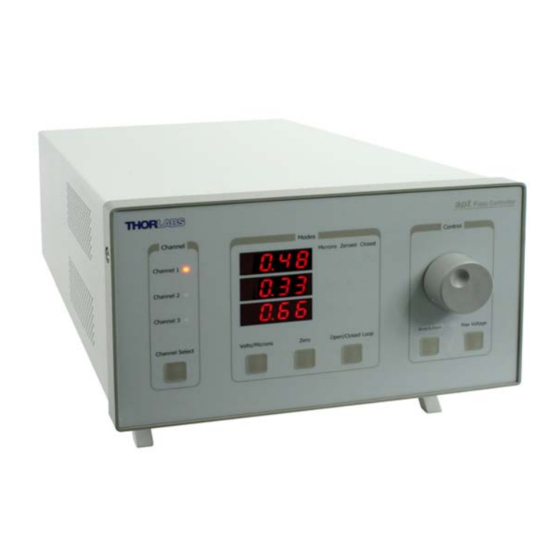
Open or closed loop control and zeroing of the piezo can also be selected from the front panel. Fig. 1.1 Three Channel Piezo Controller (BPC303) The controller is supplied with a full suite of software support tools. An intuitive graphical instrument panel allows immediate control and visualization of the operation of the piezo controller, and any other controllers that are installed in the system. - Page 5 See Section 1.2. for a full description of the Kinesis software. The key innovation of the Thorlabs range of controllers and associated mechanical products is the ease and speed with which complete automated alignment systems can be engineered at both the hardware and software level.
-
Page 6: Pc Software Overview
1.2 PC Software Overview 1.2.1 Introduction The BPC303 piezo controllers feature USB connectivity (allowing multiple units to be used together on a single PC), fully featured Graphical User Interface (GUI) panels, and extensive software function libraries for custom application development. -
Page 7: Software Upgrades
This is available either by pressing the F1 key when running the Kinesis server, or via the Start menu, Start\Programs\Thorlabs\Kinesis\Kinesis Help. 1.2.3 Software Upgrades Thorlabs operate a policy of continuous product development and may issue software upgrades as necessary. Page 4... -
Page 8: Chaper 2 Safety
Three-Channel Piezo Controller, 75 V to 150 V Chapter 2 Safety 2.1 Safety Information For the continuing safety of the operators of this equipment, and the protection of the equipment itself, the operator should take note of the Warnings, Cautions and Notes throughout this handbook and, where visible, on the product itself. -
Page 9: Chaper 3 Set Up
If you experience any problems when installing software, contact Thorlabs on +44 (0)1353 654440 and ask for Technical Support. DO NOT CONNECT THE CONTROLLER TO YOUR PC YET 1) Go to Services/Downloads at www.thorlabs.com and download the Kinesis... -
Page 10: Mechanical Installation
Three-Channel Piezo Controller, 75 V to 150 V 3.2 Mechanical Installation 3.2.1 Siting The unit is designed to be mounted free standing on a shelf, benchtop or similar surface. Caution When siting the unit, it should be positioned so as not to impede the operation of the rear panel power supply switch. -
Page 11: Electrical Installation
The unit must be connected only to an earthed fused supply of 85V to 264V. Use only power supply cables supplied by Thorlabs, other cables may not be rated to the same current. The unit is shipped with appropriate power cables for use in the UK, Europe and the USA. -
Page 12: Rear Panel Connections
Three-Channel Piezo Controller, 75 V to 150 V 3.3.4 Rear Panel Connections EXT IN (-) EXT IN (-) EXT IN (-) EXT IN (+) EXT IN (+) EXT IN (+) PIEZO IN PIEZO IN PIEZO IN HV OUT HV OUT HV OUT Fig. - Page 13 Caution It is recommended that only cables supplied by Thorlabs are used to connect the piezo drive outputs. Other cables may not be rated to the same specification. If using third party cables for the high voltage output, the HV cable used must have insulation able to withstand 200V DC / 150V AC.
-
Page 14: Front Panel Controls And Indicators
Three-Channel Piezo Controller, 75 V to 150 V 3.4 Front Panel Controls and Indicators The front panel controls of the BPC303 piezo controller allow the unit to be operated as a standalone unit, without the need to connect to a PC. -
Page 15: Button Operation
Chapter 3 Set Up Zero Button – Initiates the zeroing routine - see Section 3.5.2. Note The ‘Zero’ and ‘Open/Closed Loop’ buttons perform the same function as their respective equivalents on the software GUI panel. If a control PC is connected, pressing these buttons has the same effect as pressing the correspondingGUI button. -
Page 16: Max Voltage Button
Three-Channel Piezo Controller, 75 V to 150 V To adjust the offset zero: 1) Click the ‘Zero’ button. Notice that the ‘Zeroed’ led flashes to indicate that zeroing is in progress and the displayed position counts down towards zero (but may not reach zero). -
Page 17: Adjusting The Display Brightness
- see the Getting Started guide for more information 4) Run the Kinesis software Start/Programs/Thorlabs/Kinesis/Kinesis. 5) Your Piezo Controller is now ready for use. See Chapter 4 of this manual for a brief tutorial on operation of the unit. -
Page 18: Verifying Software Operation
Three-Channel Piezo Controller, 75 V to 150 V 3.9 Verifying Software Operation 3.9.1 Initial Setup 1) Install the software as detailed in Section 3.1. Connect the controller to the actuators (see Section 3.3.4.) and the PC, then switch ON. Wait approximately 5 seconds for the system to settle. Caution In applications requiring the highest level of accuracy and repeatability, it is recommended that the controller unit is powered up approximately 30 minutes... -
Page 19: Chaper 4 Pc C Operation - Tutorial
Please consult your system administrator or contact Thorlabs technical support for more details. 4.2 Using the Kinesis Software The Kinesis software allows the user to interact with any number of hardware control units connected to the PC USB Bus. - Page 20 Three-Channel Piezo Controller, 75 V to 150 V 1) Power up the hardware, and wait until the BPC303 has finished booting up, then run the software - Start/All Programs/Thorlabs/Kinesis/Kinesis. The software registers automatically the units connected on the USB bus and displays the associated GUI panels as shown in Fig.
-
Page 21: Setting The Position Sensor Zero
Chapter 4 PC Operation - Tutorial 4.3 Setting the Position Sensor Zero The position sensor is a strain gauge fitted to the piezo actuator. Due to limitations in manufacture, the strain gauge may give a small signal when the actuator is at zero position with zero volts applied. -
Page 22: Jogging The Piezos
Three-Channel Piezo Controller, 75 V to 150 V 4) Enter a position. This can be entered directly into the field, or by clicking on the up/down arrows. 5) Click the arrow to save the change. Notice that the position display counts up to 10.00 to indicate a move to a position 10µm from the Zero datum. -
Page 23: Using The Controller As A Piezo Amplifier
Chapter 4 PC Operation - Tutorial 4.5 Using the Controller as a Piezo Amplifier Certain applications may require the piezo to be driven by a voltage generated from an external source (e.g. 0 to 10V output). To achieve this, the controller must handle the amplification from 10V to 75V. -
Page 24: Thermal Shutdown
Three-Channel Piezo Controller, 75 V to 150 V 4) Open-loop, display position (microns) measured by sensor. Note These options can be selected through the GUI panel buttons, or by calling the appropriate function from the application software. 4.7 Thermal Shutdown In order to protect the piezo driver card from overheating due to abnormal load conditions, the electronics contains thermal protection circuitry. -
Page 25: Using The Mzf001 Joystick
Chapter 4 PC Operation - Tutorial In Force Sensor mode, the jog arrows are hidden. Fig. 4.5 GUI Display - Force Sensor Mode 5) The force sensor may display an offset when no contact is apparent. The Zero button is used to remove any latent offset, such that the sensor only detects a force when contact is experienced. - Page 26 Three-Channel Piezo Controller, 75 V to 150 V In order to establish control over a particular axis, the joystick axes must be associated with the corresponding channels of the related controller. This is achieved by setting the joystick ID switch, located on the underside of the joystick console, and the channel ident switches on the rear panel of the BPC controller to the same number.
-
Page 27: Load Response
Chapter 4 PC Operation - Tutorial 4.10 Load Response The response of the BPC303 to varying load and frequencies is shown below. Fig. 4.6 Response of BPC303 to Varying Loads and Frequencies Page 24 Rev F Dec 2018... -
Page 28: Chaper 5 Software Reference
Three-Channel Piezo Controller, 75 V to 150 V Chapter 5 Software Reference 5.1 GUI Panel The following screen shot shows the graphical user interface (GUI) (one panel per card fitted) displayed when accessing the controller using the Kinesis software. Fig. 5.1 Piezo Driver Software GUI Note The serial number of the driver card associated with the GUI panel is displayed in the top right hand corner. -
Page 29: Settings Panel
5.2.1 Persisting Settings to the Hardware Many of the parameters that can be set for the BPC303 Piezo Controller can be stored (persisted) within the unit itself, such that when the unit is next powered up these settings are applied automatically. This is particularly important when the controller is being used manually in the absence of a PC and USB link. -
Page 30: Control Tab
The default values of 100 (proportional) and 100 (integral) have been optimised to work with most Thorlabs piezo actuators, so usually these values can be left unchanged. -
Page 31: Advanced Tab
This must be set up to suit the maximum specified operating voltage of the piezo actuator connected to the unit. Most Thorlabs piezo actuators are specified for either 75V or 150V maximum operation. In general, the maximum voltage should not be exceeded because it can cause damage to the piezo actuator. - Page 32 Three-Channel Piezo Controller, 75 V to 150 V Input Settings Input Source - the voltage output of the unit is a sum of up to 3 contributing sources: the software (GUI) 'Output Voltage' setting, the front panel potentiometer and the external input source, which in turn can be set to Hub Channel 1, Hub Channel 2 or 'EXT IN' SMA connector - see Analogue Input Source parameter.
-
Page 33: Appendix A Rear Panel Connector Pinout Details
† Power supply for the piezo actuator feedback circuit. It must not be used to drive any other circuits or devices. * This signal is applicable only to Thorlabs actuators. It enables the system to identify the piezo extension associated with the actuator. - Page 34 Three-Channel Piezo Controller, 75 V to 150 V A.2 Rear Panel AUX I/O Connector A.2.1 Pin Identification This female 15-pin D-Type connector exposes a number of internal electrical signals. For convenience, a number of logic inputs and outputs are included, thereby eliminating the need for extra PC based IO hardware.
- Page 35 Appendix A Rear Panel Connector Pinout Details A.2.2 Digital Outputs All digital outputs are of the open-collector type, with a 330 Ohm series resistor. When the output is set to a logic zero (which is also the default state), it behaves as open circuit.
- Page 36 Three-Channel Piezo Controller, 75 V to 150 V A.2.3 Digital Inputs The digital inputs used in the controller are of the standard CMOS logic gate type with TTL compatible input levels and a built-in pull-up resistor (10 kOhm to +5V). They can be connected directly to mechanical switches, open-collector type outputs or most type of logic outputs.
- Page 37 Appendix A Rear Panel Connector Pinout Details As this output is actively driven, it can be connected, for example, to an oscilloscope without a need for an external pull-up resistor. It can also be used to drive most optocouplers. A.2.5 Trigger Input The Trigger inputs are electrically identical to the digital inputs (i.e.
- Page 38 Three-Channel Piezo Controller, 75 V to 150 V A.3 Rear Panel INTERCONNECT Connector A.3.1 Pin Identification Although this Male 9-Pin D-type connector exposes internal electrical signals for use with serial communications or an external remote control handset, no firmware support is available at present. The pin functions are detailed in in Fig.
-
Page 39: Appendix B Preventive Maintenance
The equipment contains no user servicable parts. There is a risk of electrical shock if the equipment is operated with the covers removed. Only personnel authorized by Thorlabs Ltd and trained in the maintenance of this equipment should remove its covers or attempt any repairs or adjustments. Maintenance is limited to safety testing and cleaning as described in the following sections. -
Page 40: Appendix C Specifications And Associated Parts 3
Three-Channel Piezo Controller, 75 V to 150 V Appendix C Specifications and Associated Parts C.1 Specifications Parameter Value Piezoelectric Output (SMC Male) Voltage Output 75 V, 100 V, and 150 V DC/channel Max Output Current* Voltage Stability 100ppm over 24 hours (after 30 mins warm up time) Noise <3m V RMS Typical Piezo Capacitance... - Page 41 Appendix C Specifications and Associated Parts Parameter Value Housing Dimensions (W x D x H) 240 x 360 x 133mm (9.5 x 14.2 x 5.2 in.) 6.7kg (14.75 lbs) Weight: * The maximum current quoted opposite is available only to drive one channel at a time.
-
Page 42: Appendix D Piezo Operation - Background
– see Fig. D.1. In this way, the distance from positive to negative electrodes is very small. A large field gradient can therefore be obtained with a modest drive voltage (75 V in the case of Thorlabs actuators). expansion piezoelectric... - Page 43 Some Thorlabs nanopositioning actuators have position sensing, others do not. The Piezoelectric control module allows both types to be controlled.
- Page 44 Three-Channel Piezo Controller, 75 V to 150 V moving open loop control part demand actuator moving closed loop control part demand a + b/s actuator sensor Fig. D.3 Open loop and closed loop control The result of using closed-loop control is a linear relationship between demand (voltage) and measured position –...
-
Page 45: Appendix E Regulatory
Appendix E Regulatory Appendix E Regulatory E.1 Declarations Of Conformity E.1.1 For Customers in Europe See Section E.2. E.1.2 For Customers In The USA This equipment has been tested and found to comply with the limits for a Class A digital device, persuant to part 15 of the FCC rules. - Page 46 Three-Channel Piezo Controller, 75 V to 150 V E.2 CE Certification Page 43 22883-D03...
-
Page 47: Appendix F Thorlabs Worldwide Contacts
Waste treatment is your own responsibility. "End of life" units must be returned to Thorlabs or handed to a company specializing in waste recovery. Do not dispose of the unit in a litter bin or at a public waste disposal site. - Page 48 www.thorlabs.com...
Need help?
Do you have a question about the BPC303 and is the answer not in the manual?
Questions and answers