
Related Manuals for THORLABS BSC202


Summary of Contents for THORLABS BSC202
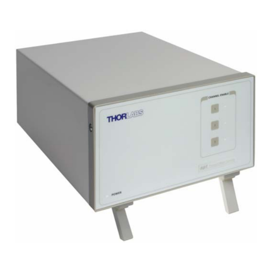
- Page 1 BSC202 and BSC203 Benchtop Stepper Motor Controller User Guide Original Instructions...
-
Page 2: Table Of Contents
Contents Chapter 1 Safety ..................... 4 1.1 Safety Information .................. 4 1.2 General Warnings .................. 4 Chapter 2 Overview..................5 2.1 Introduction ..................... 5 2.2 APT PC Software Overview ..............7 2.2.1 Introduction ......................7 2.2.2 APTUser Utility ....................8 2.2.3 APT Config Utility .................... - Page 3 Appendix C Preventive Maintenance ............57 Appendix D Specifications and Associated Parts ........58 Appendix E Motor Control Method Summary ........... 60 Appendix F Stepper Motor Operation - Background ........ 64 Appendix G Regulatory ................70 Appendix H Thorlabs Worldwide Contacts ..........75...
-
Page 4: Chapter 1 Safety
Chapter 1 Safety 1.1 Safety Information For the continuing safety of the operators of this equipment, and the protection of the equipment itself, the operator should take note of the Warnings, Cautions and Notes throughout this handbook and, where visible, on the product itself. The following safety symbo ls may be u sed throughout the h andbook and on the equipment itself. -
Page 5: Chapter 2 Overview
Chapter 2 Overview 2.1 Introduction The BSC202 and BSC203 2- and 3-channel Stepper Motor Controllers are the next generation of enhanced controllers using the familiar APTUser interface. Many new features are provided, including a choice between trapezoidal and S-shaped velocity profiles, a higher theoretical microstep resolution (409600 for a 200 full step motor) and speeds more than twice that achieved by its predecessors. - Page 6 Fo r simplicity of operation, the apt™ software incorporates pre-configured settings for each of th e Thorlabs stages an d actuators, while still exp osing all parameters individually for use with other stepper motor driven systems.
-
Page 7: Apt Pc Software Overview
Two-, and Three-Channel Stepper Motor Controller 2.2 APT PC Software Overview 2.2.1 Introduction As a member of the APT range of cont rollers, the BSC20 2 and BSC203 stepper controllers share ma ny of the a ssociated software benefits. This includes USB connectivity (allowing multiple units to be used together on a single PC), fully featured Graphical User Interface (GUI) panels, and extensive software function libraries for custom application development. -
Page 8: Aptuser Utility
Chapter 2 2.2.2 APTUser Utility The APTUser application allows the user to interact with a number of APT hardware control units connected to the ho st PC. This program displays multiple graphical instrument panels to allow multiple APT units to be controlled from the same screen. All basic operating parameters can be altered and, similarly, all operations (such as motor moves) can be initiated. -
Page 9: Apt Config Utility
Two-, and Three-Channel Stepper Motor Controller 2.2.3 APT Config Utility There are many system par ameters and co nfiguration settings associated with the operation of the APT Server. Most can be directly accessed using the various graphical panels, however there are several system wide settings that can be made 'off-line' before running the APT software. -
Page 10: Apt Server (Activex Controls)
Chapter 2 2.2.4 APT Server (ActiveX Controls) ActiveX Controls are re -usable compiled software components that supp ly both a graphical user interface and a pro grammable interface. Many such Co ntrols are available for Windows applications development, providing a large range of re-usable functionality. -
Page 11: Software Upgrades
This CD contai ns a comple te range of tutori al samples and coding hints and tips, together with handbooks for all the APT controllers. 2.2.5 Software Upgrades Thorlabs operate a policy of continuous product development and may issue software upgrades as necessary. Detailed instructions on installing upgrades are included on the APT Software... -
Page 12: Chapter 3 Getting Started
If you experience any problems when installing software, contact Thorlabs on +44 (0)1353 654440 and ask for Technical Support. DO NOT CONNECT THE CONTROLLER TO YOUR PC YET 1) Download the software from www.thorlabs.com. -
Page 13: Mechanical Installation
Two-, and Three-Channel Stepper Motor Controller 3.2 Mechanical Installation 3.2.1 Siting The unit is designed to be mounted free standing on a shelf, benchtop or simil ar surface. Caution When siting the unit, it should be positioned so as not to impede the operation of the rear panel power supply switch. -
Page 14: Electrical Installation
Shock Warning The unit must be connected only to an earthed fused supply of 110 to 230V. Use only power supply cables supplied by Thorlabs, other cables may not be rated to the same current. The unit is shipped to the UK, Europe and the USA, with the appropriate power plug already fitted. -
Page 15: Rear Panel Connections
Two-, and Three-Channel Stepper Motor Controller 3.3.4 Rear Panel Connections INTERCONNECT Fig. 3.1 Rear panel connections MOTOR DRIVE - (15-Pin D-Type, Female) Provides connection to the actuator. This connector provides all phase current drive and encoder feedback connections to drive a range of encoded and non-encoded stepper motors - see Section A.3. CONTROL I/O - (15-Pin D-Type, Female) The ‘CONTROL I/O’... -
Page 16: Front Panel Controls And Indicators
LED is lit when the channel is enabled. Disabling the channel allows the motor actuator to be moved manually. Note On BSC202 units, the Channel 3 LED is not used. 3.5 Connecting The Hardware 1) Perform the mechanical installation as detailed in Section 3.2. -
Page 17: Select The Stage Type (Using Aptconfig)
1) Shut down all applications using the APT server (e .g. APT User or your own custom application). 2) Run the APT Config utility - Start/All Programs/Thorlabs/APT Config/APT Config. 3) From the 'APT Configuration Utility' window, click the 'Stage' tab. -
Page 18: Verifying Software Operation
Chapter 3 Caution The following items relate to the single channel Drive Cards fitted to the controller, and not the parent 3-channel controller housing. 4) In the ‘Motor’ field, select the serial number of the drive card to be configured. The ‘Channel’... - Page 19 Two-, and Three-Channel Stepper Motor Controller 2) Check that the act uator type an d serial n umber associated in Section 3.6. are displayed in the GUI panel. 3) Click the ‘Ident’ button. The associated channel LED on the fron t panel of the controller flashes.
-
Page 20: Chapter 4 Operation - Tutorial
Chapter 4 Operation - Tutorial 4.1 Introduction The following brief tutorial guides the user through a typica l series of moves an d parameter adjustments performed using the PC based APT software. It assumes that the unit is electrically connected to the stage, and that the APT Software is alre ady installed - see Section 3.1. -
Page 21: Homing Motors
Two-, and Three-Channel Stepper Motor Controller 1) Run the APT User program - Start/Programs/Thorlabs/APT User/APT User. Note The channel functionality of the BSC203 motor controller is accessed via a single channel GUI panel, one panel for each motor drive card fitted. -
Page 22: Moving To An Absolute Position
Chapter 4 4.4 Moving to an Absolute Position Absolute moves are mea sured in real world units (e.g. millimetres), relative to the Home position. 1) Click the position display. Fig. 4.3 Absolute Position Popup Window 2) Enter 3.0 into the pop up window 3) Click ‘OK’. -
Page 23: Changing Motor Parameters
Two-, and Three-Channel Stepper Motor Controller 4.5 Changing Motor Parameters Moves are performed using a trapezoidal velocity profile (see Appendix F , Section F.1.3.). The velocity settings relate to the maximum veloci ty at which a mo ve is performed, and the acceleration at which the motor speeds up from zero to maximum velocity. -
Page 24: Jogging
Chapter 4 4.6 Jogging During PC operation, the motor actuators are jogged using the GUI panel arrow keys. There are two jogging modes available, ‘Single Step’ and ‘Continuous’. In ‘Single Step’ mode, the motor moves by the ste p size specifie d in the Ste p Distance parameter. -
Page 25: Graphical Control Of Motor Positions (Point And Move)
Two-, and Three-Channel Stepper Motor Controller 4.7 Graphical Control Of Motor Positions (Point and Move) The GUI panel display can be changed to a graphical display, showing the position of the motor channel(s). Moves to absolute positions can then be initiated by positioning the mouse within the display and clicking. - Page 26 Chapter 4 The graphical panel has two modes of operation, ‘Jog’ and ‘Move’, which are selected by clicking the buttons at the bottom right of the screen. Move Mode When ‘Move’ is selected, the motors move to an absolute position which corresponds to the position of the cursor within the screen.
-
Page 27: Setting Move Sequences
Two-, and Three-Channel Stepper Motor Controller 4.8 Setting Move Sequences This section explains how to set move sequences, allowing several positions to be visited without user intervention. For details on moving to absolute positions initiated by a mouse click – see Section 4.11. - Page 28 Chapter 4 3) Select 'New' to display the 'Move Editor' panel. Fig. 4.9 Move Editor Window Move data is entered/displayed as follows: Dist/Pos: - the distance to move from the current position (if 'Relative' is selected) or the position to move to (if 'Absolute' is selected). Dwell Time: - after the move is performed, th e system can be set to wait for a specified time before performing the next move in the sequence.
- Page 29 Two-, and Three-Channel Stepper Motor Controller 4) Enter the required move data into the Move Editor and click OK. The move data is displayed in the main window as shown below. Fig. 4.10 Main Window with Move Data 5) Repeat step 4 as n ecessary to b uild a sequence of moves. Move data can be copied, deleted, cut/pasted and edited by righ t clicking the data line(s) and selecting the appropriate option in the pop up menu (shown below).
-
Page 30: Using A Joystick Console
Chapter 4 4.9 Using A Joystick Console The MJC001 joystick console has been designed to provide intuitive, tactile, manual positioning of the stage. The console features a two axis joystick for XY control. Up to 3 joysticks can be connected to each other, interfacing neatly into a multi-channel control application. -
Page 31: Creating A Simulated Configuration Using Apt Config
For example, an application program can be w ritten, then tested and debugged remotely, before running with the hardware. To create a simulated configuration proceed as follows: 1) Run the APT Config utility - Start/All Programs/Thorlabs/APT/APT Config. - Page 32 Chapter 4 2) Click the 'Simulator Configuration' tab. Fig. 4.13 APT Configuration Utility - Simulator Configuration Tab 3) Enter ‘LAB1’ in the Configuration Names field. 4) In the 'Simulator' field, check the ‘Enable Simulator Mode’ box. The name of the most recently used configuration file is d isplayed in the 'Current Configuration' window.
- Page 33 Two-, and Three-Channel Stepper Motor Controller 5) In the ‘Control Unit’ field, select ‘3 Ch Stepper Driver (BSC203)’. 6) Enter a 6 digit serial number. Note Each physical APT hardware unit is factory programmed with a unique 8 digit serial number. In order to simulate a set of ‘real’ hardware the Config utility allows an 8 digit serial number to be associated with each simulated unit.
-
Page 34: Stage/Axis Tab
APTUser. These parameters should not be altered for pre-defined Thorlabs stages and actuators selected using APT Config, as it may adversely affect the performance of the stage. -
Page 35: Introduction
Chapter 5 Software Reference 5.1 Introduction This chapter gives an explanation of the parameters and settings accessed from the APT software running on a PC. For information on the methods and properties which can be called via a programming interface, see Appendix E 5.2 GUI Panel The following screen shot shows the gra phical user interface (GUI) (one panel per channel) displayed when accessing the controller using the APTUser utility. -
Page 36: Ha0278T Rev H Dec
Chapter 5 Jog - used to increment or decrement the motor position. When the button is clicked, the motor is driven in the selected direction at the jog velocity one step per click. The step size and jog velocity parameters are set in the 'Settings' panel (see Section 5.3.). Travel - displays the range of travel (in millimeters or degrees) of the motor. -
Page 37: Settings Panel
Two-, and Three-Channel Stepper Motor Controller 5.3 Settings Panel When the 'Settings' button on th e GUI pan el is clicked, the 'Settings' window is displayed. This panel allows motor operation parameters such as move/jog velocities, and stage/axis information to be modified. Note that all of th ese parameters have programmable equivalents accessible through the ActiveX methods an d properties on this Control (refer to the Programming Guide in the APTServer helpfile for further details and to Section 2.2.4. - Page 38 Chapter 5 Jogs Jogs are initiated by using the ‘Jog’ keys on the GUI panel (see Section 4.6.), or via a jog handset connected to the unput logic pins exposed on the rear panel Control IO connector (see Appendix A Velocity Profile (specified in real world units, millimetres or degrees) MaxVel - the maximum velocity at which to perform a jog Accn/Dec - the ra te at which the ve locity climbs from m inimum to maximum, and...
-
Page 39: Stage/Axis Tab
Two-, and Three-Channel Stepper Motor Controller Step Distance - The distance to move when a jog command is initiated. The step size is specified in real world units (mm or degrees dependent upon the stage). Backlash Correction - The system compensates for lead screw backlash during reverse direction moves, by moving passed the demanded position by a specified amount, and then reversing. - Page 40 Chapter 5 The S-curve profile is a trap ezoidal curve with an additional 'Bow Index' parameter, which limits the rate of change of acceleration and smooths out the contours of the motion profile. The Bow Value is applied in mm/s and is derived from the Bow Index field as follows: (Bow Index -1)
- Page 41 They need to be set accordingly such that a particular stage is driven properly by the system. For Thorlabs stages, the APT Config utility can be used to associate a specific stage and axis type with the motor channel (refer to the APT Config helpfile for further details on how to associate a stage and axis).
- Page 42 Chapter 5 Stage and Axis Type - For Thorlabs stages, the stage type is displayed automatically once the axis has been associated using the APTConfig utility. For third party stages, the display shows ‘Unknown’. Caution Extreme care must be taken when modifying the stage related settings that follow.
- Page 43 ‘Steps Per Rev’ parameter is entered as full steps, not microsteps. The system automatically applies a factor of 128 microsteps per full step. The stepper motors used on the majority of Thorlabs stages/actuators have 200 full steps per rev and no gearbox fitted. For these motors the Steps Per Rev and Gearbox Ratio parameters have values of 200 and 1 respectively.
-
Page 44: Advanced Tab
Chapter 5 Persist Settings to Hardware - Many of the parameters that can be set for the BSC20x series drivers can be stored (persisted) within the unit itself, such that when the unit is next powered up these settings are applied automatically. This is particularly important when the driver is being used manually via a joystick, in the absence of a PC and USB link. - Page 45 Two-, and Three-Channel Stepper Motor Controller The trigger settings can be used to configure multiple units in a master - slave set up, thereby allowing multiple channels of motion to be synchronized. Multiple moves can then be initiated via a single software or hardware trigger command. Mode The Mode parameter sets the trigger mode for the associated channel.
- Page 46 Chapter 5 For example, consider the following diagram: motor unit A CONTROL IO Pin 12 (Trigger Out) move command Motor 1 move motor unit B Triggering Parameter setup Motor Unit A (Master) CONTROL IO Pin 4 Trigger Mode - Trig Out (Trigger In) Move Type - Relative Motor Unit B (Slave)
- Page 47 5.3.4 Joystick Tab Fig. 5.9 Joystick Settings If the optional Thorlabs joystick console is be ing used (MJC001) the follo wing parameters are used to set the velocity and acceleration limits and the direction sense of any moves initiated from the joystick.- see Section 4.9. for more details on joystick use.
-
Page 48: Appendix A Rear Panel Connector Pinout Details
Appendix A Rear Panel Connector Pinout Details A.1 Rear Panel CONTROL IO Connector The ‘CONTROL I/O’ is a 15-Pin D-Type, Female connector that exposes a number of electrical signals useful for external control. It is possible to configure a particular controller to respond to trigger inputs, generate trigger outputs or both respond to and generate a trigger output - see Section 5.3.3. - Page 49 Two-, and Three-Channel Stepper Motor Controller A.1.1 Digital/User Outputs All digital outputs are of the open-collector type, with a 330 Ohm series resistor. When the output is set to a logic zero (which is also the d efault state), it behaves as open circuit.
- Page 50 Appendix A A.1.2 Digital/User Inputs The digital inputs used in the controller are of the standard CMOS logic gate type with TTL compatible input levels and a built-in pull-up resistor (10 kOhm to +5V). They can be connected directly to mecha nical switches, open-collector type outputs or most type of logic outputs.
- Page 51 Two-, and Three-Channel Stepper Motor Controller As this output is actively driven, it can be connected, for example, to an oscilloscope without a need for an external pull-up resistor. It can also be used to d rive most optocouplers. A.1.4 Trigger Input The Trigger inputs are ekectrically identical to the digital inputs (i.e.
- Page 52 Appendix A A.1.6 +5 Volt Supply A +5 V, 250 mA supply is provided for interfacing to external circuits that require a power source. Caution Do not exceed the 250 mA maximum output current. For applications requiring higher currents an external power supply must be used. A.2 Rear Panel HANDSET Connector Provides connection to the MJC001 joystick.
- Page 53 Two-, and Three-Channel Stepper Motor Controller A.3 Rear Panel MOTOR DRIVE Connectors The ‘MOTOR DRIVE ’ is a 15-Pin D-Type, Female connector that provides connection to the motors. The pin functions are detailed in Fig. A.9. In each case the signal must be referenced to the indicated return pin in order to be true.
-
Page 54: Appendix B Using A Virtual Comm Port
Appendix B Using a Virtual Comm Port When using the low level communications protocol messages to develop client applications outside of the APT software, communication with the device is facilitated by using a virtual comms port as follows: 1) Open the device manager by selecting Start/Control Panel/Device Manager/ 2) Click ‘USB Ser ial Bus Controllers’... - Page 55 Two-, and Three-Channel Stepper Motor Controller 3) The ‘USB Device Properties’ window is displayed. 4) Select the ‘Advanced’ tab, and check the ‘Load VCP’ box. 5) Click OK, then power cycle the device being configured.
- Page 56 Appendix B 6) In the device manager, click ‘Ports (COM & LPT)’, and note the ‘APT USB Device Serial Port’ COM port number (e.g. COM3). This COM port can then be used by the client application to communicate with the device using the low level protocol messages.
-
Page 57: Appendix C Preventive Maintenance
The equipment contains no user servicable parts. There is a risk of severe electrical shock if the equipment is operated with the covers removed. Only personnel authorized by Thorlabs Ltd and trained in the maintenance of this equipment should remove its covers or attempt any repairs or adjustments. -
Page 58: Appendix D Specifications And Associated Parts
Appendix D Specifications and Associated Parts D.1 Specifications Parameter Value Input/Output Motor Drive 2-Phase Bipolar Motor Drive Output (15-Pin D-type Female) Differential Quadrature Encoder Interface Forward, Reverse Limit Switch Inputs Control IO Jog Forward (15-Pin D-type Female) Jog Back User Outputs/Inputs Single - ended analog input (0-10 Volt) Trigger In/Out 2048 Microsteps per Full Step... - Page 59 Two-, and Three-Channel Stepper Motor Controller D.2 Associated Products Product Name Part Number Stepper Motor Actuator, 4mm travel DRV001 Stepper Motor Actuator, 25mm (1”) travel, trapezoidal leadscrew DRV013 Stepper Motor Actuator, 50mm (2”) travel, trapezoidal leadscrew DRV014 Stepper Motor Drive Cable (1.25 Metres) PAA 610 Stepper Motor Drive Cable (3.0 Metres) PAA 611...
-
Page 60: Appendix E Motor Control Method Summary
Appendix E Motor Control Method Summary The 'Motor' ActiveX Control provides the functionality required for a client application to control one or more of the APT series of motor controller units. To specify the particular controller being addressed, every unit is factory programmed with a unique 8-digit serial number. - Page 61 Two-, and Three-Channel Stepper Motor Controller GetHomeParams_HomeVel Gets the homing velocity parame ter (returned by value). GetHomeParams_ZeroOffset Gets the homing zero offset parameter (returned by value). GetHWCommsOK Gets the hardware communications OK flag. GetHWLimSwitches Gets the limit switch configuration settings. GetJogMode Gets the jogging button operating modes.
- Page 62 Appendix E GetTriggerParams Gets the move triggering parameters. GetVelParamLimits Gets the maximum velocity profile parameter limits. GetVelParams Gets the velocity profile parameters. GetVelParams_Accn Gets the move acceleration (returned by value). GetVelParams_MaxVel Gets the mo ve maximum velocity (returned by value). Identify Identifies the controller by flashing unit LEDs.
- Page 63 Two-, and Three-Channel Stepper Motor Controller SetHomeParams Sets the homing sequence parameters. SetHWLimSwitches Sets the limit switch configuration settings. SetJogMode Sets the jogging button operating modes. SetJogStepSize Sets the jogging step size. SetJogVelParams Sets the jogging velocity profile parameters. SetMotorParams Sets the motor gearing parameters.
-
Page 64: Appendix F Stepper Motor Operation - Background
F.1 How A Stepper Motor Works F.1.1 General Principle Thorlabs’ actuators use a stepper motor to drive a precision lead screw. Stepper motors ope rate using the principle of magnetic attraction and repulsion to convert digital pulses into mechanical shaft rotation. The amount of rotation achieved is directly proportional to the number of input pulses generated and the spe ed is proportional to the frequency of these pulses. - Page 65 Two-, and Three-Channel Stepper Motor Controller F.1.2 Positive and Negative Moves Positive and negative are used to describe the direction of a move. A positive move means a move from a smaller absolute position to a larger one, a negative move means the opposite.
- Page 66 Appendix F The S-curve profile is a trapezoidal curve with an additional 'Bow Value' parameter, which limits the rate of change of acceleration and smooths out the contours of the motion profile. The Bow Value is applied in mm/s and is derived from the Bow Index field as follows: (Bow Index -1) Bow Value = 2...
- Page 67 Two-, and Three-Channel Stepper Motor Controller conversion is performed in ternally by the controller. If op erating via a PC (re mote mode) then the conversion is performed by the APT software. Each motor in the system has an associated electronic counter in the controller, which keeps a record of the net number of microsteps moved.
- Page 68 Appendix F F.2.4 Minimum and Maximum Positions These positions are dependent upon the stage or actuator to which the motors are fitted, and are defined as the minimum and maximum useful positions of the stage relative to the ‘Home’ position - see Fig. F.5. The distance from the Minimum position to the Maximum position is the ‘useful travel’...
- Page 69 Two-, and Three-Channel Stepper Motor Controller F.3 Error Correction F.3.1 Backlash correction The term backlash refers to the tendency of the stage to reach a different position depending on the direction of approach. Backlash can be overcome by always making the last portion of a move in the same direction, conventionally the p ositive direction.
-
Page 70: Appendix G Regulatory
Appendix G Regulatory G.1 Declarations Of Conformity G.1.1 For Customers in Europe This equipment has been tested and found to comply with the EC Directives 2004/108/EC ‘EMC Directive’ and 2006/95/EC ‘Low Voltage Directive’. Compliance was demonstrated by conformance to the following specifications which have been listed in the Official Journal of the European Communities: Safety EN61010-1: 2010 Safety requirements for electrical equipment for... - Page 71 • left over parts of units disassembled by the user (PCB's, housings etc.). If you wish to return a unit for waste recovery, please contact Thorlabs or your nearest dealer for further information. G.2.2 Waste treatment on your own responsibility If you do not return an "end of life"...
- Page 72 Appendix G 7.3 CE Certificates HA0278T Rev H Dec 2016...
- Page 73 Two-, and Three-Channel Stepper Motor Controller...
- Page 74 Appendix G HA0278T Rev H Dec 2016...
-
Page 75: Appendix H Thorlabs Worldwide Contacts
Fax: +44 (0)1353-654444 Fax: +86 (0)21-32513480 www.thorlabs.de www.thorlabs.com email: sales.uk@thorlabs.com email: chinasales@thorlabs.com Support: techsupport.uk@thorlabs.com Brazil Thorlabs Vendas de Fotônicos Ltda. Rua Riachuelo, 171 France Thorlabs SAS São Carlos, SP 13560-110 109, rue des Côtes Brazil 78600 Maisons-Laffitte Tel: +55-16-3413 7062... - Page 76 Thorlabs Inc. Thorlabs Ltd. 56 Sparta Ave Saint Thomas Place, Ely Newton, NJ07860 Cambridgeshire CB7 4EX, Tel: +1 973 579 7227 Tel: +44 (0) 1353 654440 Fax: +1 973 300 3600 Fax: +44 (0) 1353 654444 www.thorlabs.com www.thorlabs.com...
Need help?
Do you have a question about the BSC202 and is the answer not in the manual?
Questions and answers