
Subscribe to Our Youtube Channel
Related Manuals for THORLABS BSC001


Summary of Contents for THORLABS BSC001
- Page 1 STEPPER MOTOR CONTROLLER Model Number BSC001 BSC002...
- Page 2 THORLABS About the Company Thorlabs is a broad based optical technologies company with expertise in the design and manufacture of an extensive array of innovative photonics products. The product range covers optical and opto-mechanical components, tables and vibration control, nanopositioning solutions, test and measurement systems, and laser sources.
-
Page 3: Table Of Contents
Contents 1 Introduction ....................3 How to Use this Handbook ..................... 3 Handbook Structure ....................... 3 Declarations Of Conformity .................... 4 For Customers in Europe ..................4 For Customers In The USA ..................4 2 For Your Safety ..................5 Safety Information ...................... - Page 4 5 Set Up And Operation ................21 Introduction ........................21 Software Installation and Upgrade ................22 Software Installation .................... 22 Software Upgrades ....................22 System Setup ....................... 23 Assigning a Serial Number ................... 23 Manual Operation ......................24 Operation from the GUI Panel ................24 Settings Panel .....................
-
Page 5: Introduction
Chapter 1 Introduction 1.1 How to Use this Handbook This handbook contains all the information necessary to set up, program and operate the BSC series Stepper Motor Controller. For the continuing safety of the operators of this equipment, and the protection of the equipment itself, read the Safety Information in Chapter 2 before using the equipment, and carefully heed all cautionary notes. -
Page 6: Declarations Of Conformity
Operation of this equipment in a residential area is likely to cause harmful interference in which case the user will be required to correct the interference at his own expense. Changes or modifications not expressly approved by Thorlabs Ltd could void the user’s authority to operate the equipment. -
Page 7: For Your Safety
Chapter 2 For Your Safety 2.1 Safety Information For the continuing safety of the operators of this equipment, and the protection of the equipment itself, the operator should take note of the Warnings, Cautions and Notes throughout this handbook and, where visible, on the product itself. The following safety symbols may be used on the equipment: Warning, risk of danger. - Page 8 For Your Safety The following safety symbols may be used throughout the handbook: Warning. An instruction which draws attention to the risk of injury or death. Caution. An instruction which draws attention to the risks of damage to the product, process or surroundings.
-
Page 9: Overview
Chapter 3 Overview 3.1 Description The BSC001 single channel and BSC002 dual channel APT Stepper Motor Controllers use the latest high speed digital signal processing (DSP) technology to provide high resolution microstepping (25,600 steps per revolution). They allow the user to control up to 2 axes of motion, and additional axes can be driven by connecting two or more units together via a standard USB hub. -
Page 10: Apt Server (Activex Controls)
Getting Started 3.2.2 APT Server (ActiveX Controls) ActiveX Controls are re-usable compiled software components that supply both a graphical user interface and a programmable interface. Many such Controls are available for Windows applications development, providing a large range of re-usable functionality. - Page 11 BSC Series Stepper Motor Controller of the powerful functionality provided by the APT ActiveX Server (as illustrated in the system architecture diagram below).
-
Page 12: Apt User.exe
Getting Started 3.2.3 APT User.exe The APTUser application allows the user to interact with a number of APT hardware control units connected to the host PC. This program displays multiple graphical instrument panels to allow multiple APT units to be controlled simultaneously. All basic operating parameters can be altered and, similarly, all operations (such as motor moves) can be initiated. -
Page 13: Apt Config Utility
BSC Series Stepper Motor Controller 3.2.4 APT Config Utility There are many system parameters and configuration settings associated with the operation of the APT Server (ActiveX Controls). Most can be directly accessed using the various graphical panels and their associated programmable interfaces. However there are several system wide settings that can be made 'off-line' before running the APT software. -
Page 14: Front Panel Controls And Indicators
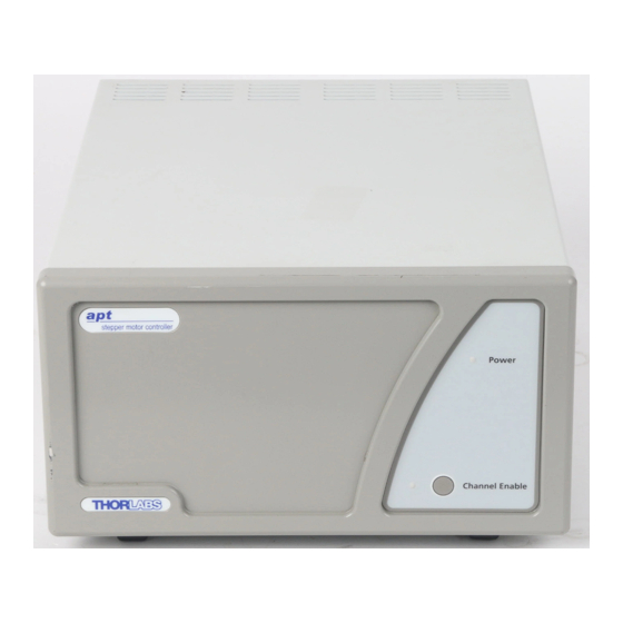
Getting Started 3.3 Front Panel Controls and Indicators Fig. 3.1 Front panel controls and indicators (dual channel version) Power LED – Indicates that power is applied to the unit. Channel 1 and Channel 2 buttons – Used to enable/disable channel functionality. The associated LED is lit when the channel is enabled. -
Page 15: Rear Panel Connections
BSC Series Stepper Motor Controller 3.4 Rear Panel Connections DRIVE CHANNEL 1 DRIVE CHANNEL 2 CONTROL I/O TRIG. OUT TRIG. IN USER I/O MOTOR CONTROL POWER 90 - 264 VAC, 47 - 63 Hz, 250 VA FUSES F1 and F2: T 3A, ANTISURGE CERAMIC bonding point Fig. - Page 16 Intentionally Blank...
-
Page 17: Principle Of Operation
(microstep). The size of the microstep depends on the resolution of the driver electronics. When used with the Thorlabs APT motor controller, the smallest angular adjustment is 0.014 degrees, resulting in a resolution of 25,600 microsteps per revolution. The mechanical... -
Page 18: Positive And Negative Moves
Principle of Operation 4.1.2 Positive and Negative Moves Positive and negative are used to describe the direction of a move. A positive move means a move from a smaller absolute position to a larger one, a negative move means the opposite. In the case of a linear actuator, a positive move takes the platform of the stage further away from the motor. -
Page 19: Positioning The Stage
BSC Series Stepper Motor Controller 4.2 Positioning the Stage 4.2.1 General Whenever a command to move a stage is received, the Control PC converts the movement specified in motion units, (e.g., mm) to a number of microsteps. It then sends a signal to the stage to move by this number of microsteps. Each motor in the system has an associated electronic counter in the Control PC, which keeps a record of the net number of microsteps moved. -
Page 20: Limit Switches
Principle of Operation 4.2.3 Limit Switches A linear stage moves between two stops, and movement outside these limits is physically impossible. Linear stages can include stages that control the angle of a platform within a certain range, although the movement of the platform is not really linear but angular. -
Page 21: Power Saving
BSC Series Stepper Motor Controller SW negative limit SW positive limit Offse t Trave l Min. position (zero) Max. position (home) -ve limit switch Fig. 4.4 Minimum and Maximum Positions 4.2.5 Power Saving The current needed to hold a motor in a fixed position is much smaller than the current needed to move it, and it is advantageous to reduce the current through a stationary motor in order to reduce heating. -
Page 22: Error Correction
Principle of Operation 4.3 Error Correction 4.3.1 Backlash correction The term backlash refers to the tendency of the stage to reach a different position depending on the direction of approach. Backlash can be overcome by always making the last portion of a move in the same direction, conventionally the positive direction. -
Page 23: Set Up And Operation
Chapter 5 Set Up And Operation 5.1 Introduction The functionality required for a client application to control a number of Stepper Motor Control units is provided by the Motor Control Object within the APT server, with manual operation being facilitated via a GUI panel (see Section 5.5.1.). Instances of this ActiveX control can be dragged from the toolbox in the development software. -
Page 24: Software Installation And Upgrade
HKEY_LOCAL_MACHINE\SOFTWARE\THORLABS\APT USER For further information, consult your system administrator. 5.2.2 Software Upgrades Thorlabs operate a policy of continuous product development and may issue software upgrades as necessary. Detailed instructions on installing upgrades are included on the APT Software CD ROM. -
Page 25: System Setup
BSC Series Stepper Motor Controller 5.3 System Setup 1) Install the APT software as detailed in Section 5.2. 2) Install the electronic hardware and connect the controller to the relevent axes of the associated stages (see Chapter 6). 3) Run the APTUser utility and check that the unit powers up. 4) For each Stepper Motor Controller in your system, fit the interlock plug (supplied) to the MOTOR CONTROL connector on the rear panel. -
Page 26: Manual Operation
Set Up And Operation 5.5 Manual Operation 5.5.1 Operation from the GUI Panel Fig. 5.3 Motor controller software GUI (dual channel version) The software drivers consist of several ‘objects’, which in turn contain ‘Methods’ and ‘Properties’. The ‘Stepper Motor’ object contains the methods which facilitate the programmed operation of the controller. - Page 27 BSC Series Stepper Motor Controller Moving - lit when the motor is in motion. Enabled - applies power to the motor. With the motor enabled, the LED in the button is lit. Note. The motor cannot be positioned using the knob on the motor shaft if the drive is 'Enabled'.
-
Page 28: Settings Panel
Set Up And Operation 5.5.2 Settings Panel When the 'Settings' button on the GUI panel is clicked, the 'Settings' window is displayed for the selected channel. This panel allows motor operation parameters such as move/jog velocities, and stage/axis information to be modified. Note that all of these parameters have programmable equivalents accessible through the ActiveX methods and properties on this Control (refer to the Programming Guide in the MG17Base helpfile for further details). - Page 29 BSC Series Stepper Motor Controller Jogs Jogs are initiated by using the ‘Jog’ keys on the GUI panel or by using the optional jog handset unit. Velocity Profile (specified in real world units, millimetres or degrees) MinVel - the minimum velocity at which to start and end a jog MaxVel - the maximum velocity at which to perform a jog Accn/Dec - the rate at which the velocity climbs from minimum to maximum, and slows from maximum to minimum...
- Page 30 For Thorlabs stages, the APT Config utility can be used to associate a specific stage and axis type with the motor channel (refer to the APT Config helpfile for further details on how to associate a stage and axis).
- Page 31 BSC Series Stepper Motor Controller Stage and Axis Type - For Thorlabs stages, the stage type is displayed automatically once the axis has been associated using the APTConfig utility. For third party stages, the display shows ‘Unknown’. Caution. Extreme care must be taken when modifying the stage related settings which follow.
- Page 32 Notes. • The stepper motors used on the majority of Thorlabs stages/actuators have 200 full steps per rev and no gearbox fitted. For these motors the Steps Per Rev and Gearbox Ratio parameters have values of 200 and 1 respectively. As an exception to this, the ZST family of actuators use 24 steps per rev stepper motors fitted with a 76:1 reduction gearbox.
-
Page 33: Installation And Maintenance
Chapter 6 Installation And Maintenance 6.1 Mechanical Installation 6.1.1 Siting The Stepper Motor controller is designed to be mounted free standing on a shelf, benchtop or similar surface. Caution. When siting the unit, it should be positioned so as not to impede the operation of the rear panel power supply switch. -
Page 34: Electrical Installation
Warnings. • The unit must be connected only to an earthed fused supply of 100 to 240V. • Use only power supply cables supplied by Thorlabs, other cables may not be rated to the same current. • The unit is shipped to the UK, Europe and the USA, with the appropriate power plug already fitted. -
Page 35: Electrical Connections
BSC Series Stepper Motor Controller 6.2.4 Electrical Connections DRIVE CHANNEL 1 DRIVE CHANNEL 2 CONTROL I/O TRIG. OUT TRIG. IN USER I/O MOTOR CONTROL POWER 90 - 264 VAC, 47 - 63 Hz, 250 VA FUSES F1 and F2: T 3A, ANTISURGE CERAMIC manual control pad stage motor connections... -
Page 36: Rear Panel Motor Control Connector
Installation And Maintenance 6.2.5 Rear Panel Motor Control Connector Note. If the motor control connector is not used, the terminator supplied must be fitted. The ‘Motor I/O’ connector exposes a number of electrical signals useful for external control. Interlock enable lines are used to enable/disable the motor drive outputs and are a useful mechanism for implementing an external emergency stop feature. -
Page 37: Rear Panel User I/O Connector
BSC Series Stepper Motor Controller 6.2.6 Rear Panel User I/O Connector The User I/O connector exposes a number of internal electrical signals. For convenience, a number of logic inputs and outputs are included, thereby negating the need for extra PC based IO hardware. Using the APT support software, these user programmable logic lines can be deployed in applications requiring control of external devices such a relays, light sources and other auxilliary equipment. - Page 38 Installation And Maintenance pull up resistor pin 8 20mA max. to 11 d.c. supply 5V max. Ω user output pin 27 to 36 Fig. 6.3 Open collector output details pin 12 Ω to 17 user input pin 27 to 36 Fig.
-
Page 39: Rear Panel Drive Channel Connectors
BSC Series Stepper Motor Controller 6.2.7 Rear Panel Drive Channel Connectors The ‘DRIVE CHANNEL’ connectors provide connection to the motors. The pin functions are the same for each channel and are detailed in Fig. 6.5. In each case the signal must be referenced to the indicated return pin in order to be true. 25 24 23 22 21 20 19 18 17 16 15 14... -
Page 40: Preventive Maintenance
Only personnel authorized by Thorlabs Ltd and trained in the maintenance of this equipment should remove its covers or attempt any repairs or adjustments. Maintenance is limited to safety testing and cleaning as described in the following sections. -
Page 41: Specifications And Associated Products
Chapter 7 Specifications and Associated Products 7.1 Specifications Power Supply: Voltage 100 to 240 VAC Frequency 50 - 60 Hz Power 200 W Fuse Dimensions (W x D x H) 245 x 130 x 330 mm (9.6 x 5.1 x 13 in.) Weight 6 kg (13 lb) Microstep capability... - Page 42 Intentionally Blank...
- Page 43 Highly stable, tunable laser diodes with integrated electronics Product Warranty Optical powermeters All Thorlabs products are covered by a manufacturers warranty against faulty Fabry-Perot interferometer and spectrum workmanship and materials, valid for 12 analyzers months from the date of original purchase.
- Page 44 THORLABS © Thorlabs 2004 Printed in UK (1204) Thorlabs Ltd. Saint Thomas Place Cambridgeshire CB7 4EX, UK Tel: +44 (0) 1353 654440 Fax: +44 (0) 1353 654444 www.thorlabs.com ha 0115T Issue 4...
Need help?
Do you have a question about the BSC001 and is the answer not in the manual?
Questions and answers