Table of Contents
Advertisement
Quick Links
Advertisement
Table of Contents

Related Manuals for THORLABS BSC103


Summary of Contents for THORLABS BSC103
- Page 1 BSC103 Benchtop Stepper Motor Controller User Guide...
-
Page 2: Table Of Contents
Contents Chapter 1 Safety ..................... 4 1.1 Safety Information .................. 4 1.2 General Warnings .................. 4 Chapter 2 Overview..................5 2.1 Introduction ..................... 5 2.2 APT PC Software Overview ..............7 2.2.1 Introduction ......................7 2.2.2 APTUser Utility ....................8 2.2.3 APT Config Utility .................... - Page 3 Appendix B Preventive Maintenance ............55 Appendix C Specifications and Associated Parts ........56 Appendix D Motor Control Method Summary ........... 58 Appendix E Stepper Motor Operation - Background ........ 62 Appendix F Regulatory ................67 Appendix G Thorlabs Worldwide Contacts ..........71...
-
Page 4: Chapter 1 Safety
Chapter 1 Safety 1.1 Safety Information For the continuing safety of the operators of this equipment, and the protection of the equipment itself, the operator should take note of the Warnings, Cautions and Notes throughout this handbook and, where visible, on the product itself. The following safety symbols may be used throughout the handbook and on the equipment itself. -
Page 5: Chapter 2 Overview
& stages in the Thorlabs range. To facilitate connection to third party actuators and motors, Thorlabs offers a breakout board (please see Appendix C for details). The unit combines the latest high speed digital signal processors (DSP) with low-noise analog electronics and ActiveX®... - Page 6 For simplicity of operation, the apt™ software incorporates pre-configured settings for each of the Thorlabs stages and actuators, while still exposing all parameters individually for use with other stepper motor driven systems.
-
Page 7: Apt Pc Software Overview
2.2 APT PC Software Overview 2.2.1 Introduction As a member of the APT range of controllers, the BSC102 and BSC103 stepper controllers share many of the associated software benefits. This includes USB connectivity (allowing multiple units to be used together on a single PC), fully featured Graphical User Interface (GUI) panels, and extensive software function libraries for custom application development. -
Page 8: Aptuser Utility
Chapter 2 2.2.2 APTUser Utility The APTUser application allows the user to interact with a number of APT hardware control units connected to the host PC. This program displays multiple graphical instrument panels to allow multiple APT units to be controlled simultaneously. All basic operating parameters can be altered and, similarly, all operations (such as motor moves) can be initiated. -
Page 9: Apt Config Utility
Two-, and Three-Channel Stepper Motor Controller 2.2.3 APT Config Utility There are many system parameters and configuration settings associated with the operation of the APT Server. Most can be directly accessed using the various graphical panels, however there are several system wide settings that can be made 'off-line' before running the APT software. -
Page 10: Apt Server (Activex Controls)
With the APT system, ActiveX Controls are deployed to allow direct control over (and also reflect the status of) the range of electronic controller units, including the BSC103 stepper motor controller. Software applications that use ActiveX Controls are often referred to as 'client applications'. -
Page 11: Software Upgrades
This CD contains a complete range of tutorial samples and coding hints and tips, together with handbooks for all the APT controllers. 2.2.5 Software Upgrades Thorlabs operate a policy of continuous product development and may issue software upgrades as necessary. Detailed instructions on installing upgrades are included on the APT Software... -
Page 12: Chapter 3 Getting Started
If you experience any problems when installing software, contact Thorlabs on +44 (0)1353 654440 and ask for Technical Support. DO NOT CONNECT THE CONTROLLER TO YOUR PC YET 1) Insert the CD into your PC. -
Page 13: Mechanical Installation
Two-, and Three-Channel Stepper Motor Controller 3.2 Mechanical Installation 3.2.1 Siting The unit is designed to be mounted free standing on a shelf, benchtop or similar surface. Caution When siting the unit, it should be positioned so as not to impede the operation of the rear panel power supply switch. -
Page 14: Electrical Installation
Shock Warning The unit must be connected only to an earthed fused supply of 110 to 230V. Use only power supply cables supplied by Thorlabs, other cables may not be rated to the same current. The unit is shipped to the UK, Europe and the USA, with the appropriate power plug already fitted. -
Page 15: Rear Panel Connections
Two-, and Three-Channel Stepper Motor Controller 3.3.3 Rear Panel Connections 85 - 264 VAC 47 - 63Hz 250VA FUSES F1 and F2 T3.15A ANTISURGE CERAMIC USER IO Fig. 3.1 Rear panel connections MOTOR DRIVE - (15-Pin D-Type, Female) Provides connection to the actuator. This connector provides all phase current drive and encoder feedback connections to drive a range of encoded and non-encoded stepper motors - see Section A.2. -
Page 16: Front Panel Controls And Indicators
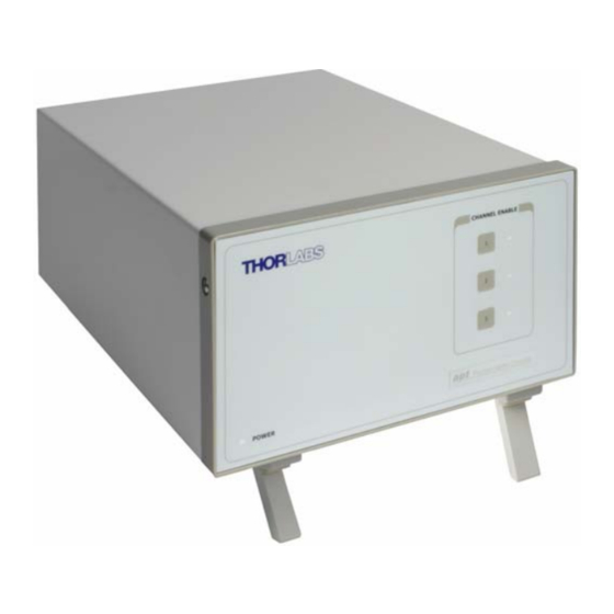
Chapter 3 3.4 Front Panel Controls and Indicators CHANNEL ENABLE Precision Motion Controller Power Fig. 3.2 Front panel controls and indicators Power LED – Indicates that power is applied to the unit. CHANNEL ENABLE buttons – Used to enable/disable channel functionality. The associated LED is lit when the channel is enabled. -
Page 17: Select The Stage Type (Using Aptconfig)
(e.g. for a custom stage type not selectable using the APT Config utility). Note The BSC103 APT stepper controller unit can be fitted with up to three SCC101 stepper motor drive cards. Each card behaves as a discrete unit with its own GUI control panel. -
Page 18: Verifying Software Operation
Chapter 3 Caution The following items relate to the single channel SCC101 Drive Cards fitted to the controller, and not the parent 3-channel controller housing. 4) In the ‘Motor’ field, select the serial number of the SCC101 drive card to be configured. - Page 19 Two-, and Three-Channel Stepper Motor Controller 2) Check that the actuator type and serial number associated in Section 3.6. are displayed in the GUI panel. 3) Click the ‘Ident’ button. The associated channel LED on the front panel of the controller flashes.
-
Page 20: Chapter 4 Operation - Tutorial
Chapter 4 Operation - Tutorial 4.1 Introduction The following brief tutorial guides the user through a typical series of moves and parameter adjustments performed using the PC based APT software. It assumes that the unit is electrically connected as shown in Section 3.3.3. and that the APT Software is already installed - see Section 3.1. -
Page 21: Homing Motors
1) Run the APT User program - Start/Programs/Thorlabs/APT User/APT User. Note The channel functionality of the BSC103 motor controller is accessed via a single channel GUI panel, one panel for each motor drive card fitted. Notice how the DRV113 actuator type, selected in Section 3.6. is displayed in the ‘Settings’... -
Page 22: Moving To An Absolute Position
Chapter 4 4.4 Moving to an Absolute Position Absolute moves are measured in real world units (e.g. millimetres), relative to the Home position. 1) Click the position display. Fig. 4.3 Absolute Position Popup Window 2) Enter 3.0 into the pop up window 3) Click ‘OK’. -
Page 23: Changing Motor Parameters
Two-, and Three-Channel Stepper Motor Controller 4.5 Changing Motor Parameters Moves are performed using a trapezoidal velocity profile (see Appendix E , Section E.1.3.). The velocity settings relate to the maximum velocity at which a move is performed, and the acceleration at which the motor speeds up from zero to maximum velocity. -
Page 24: Jogging
Chapter 4 4.6 Jogging During PC operation, the motor actuators are jogged using the GUI panel arrow keys. There are two jogging modes available, ‘Single Step’ and ‘Continuous’. In ‘Single Step’ mode, the motor moves by the step size specified in the Step Distance parameter. -
Page 25: Graphical Control Of Motor Positions (Point And Move)
Note The channel functionality of the BSC103 motor controller is accessed via a single channel GUI panel, one panel for each SCC101 motor drive card fitted. The Channel 2 parameters are greyed out. - Page 26 Chapter 4 The graphical panel has two modes of operation, ‘Jog’ and ‘Move’, which are selected by clicking the buttons at the bottom right of the screen. Move Mode When ‘Move’ is selected, the motors move to an absolute position which corresponds to the position of the cursor within the screen.
-
Page 27: Setting Move Sequences
Two-, and Three-Channel Stepper Motor Controller 4.8 Setting Move Sequences This section explains how to set move sequences, allowing several positions to be visited without user intervention. For details on moving to absolute positions initiated by a mouse click – see Section 4.9. - Page 28 Chapter 4 3) Select 'New' to display the 'Move Editor' panel. Fig. 4.9 Move Editor Window Move data is entered/displayed as follows: Dist/Pos: - the distance to move from the current position (if 'Relative' is selected) or the position to move to (if 'Absolute' is selected). Dwell Time: - after the move is performed, the system can be set to wait for a specified time before performing the next move in the sequence.
- Page 29 Two-, and Three-Channel Stepper Motor Controller 4) Enter the required move data into the Move Editor and click OK. The move data is displayed in the main window as shown below. Fig. 4.10 Main Window with Move Data 5) Repeat step 4 as necessary to build a sequence of moves. Move data can be copied, deleted, cut/pasted and edited by right clicking the data line(s) and selecting the appropriate option in the pop up menu (shown below).
-
Page 30: Creating A Simulated Configuration Using Apt Config
To create a simulated configuration proceed as follows: 1) Run the APT Config utility - Start/All Programs/Thorlabs/APT/APT Config. 2) Click the 'Simulator Configuration' tab. Fig. 4.13 APT Configuration Utility - Simulator Configuration Tab 3) Enter ‘LAB1’... - Page 31 Two-, and Three-Channel Stepper Motor Controller 4) In the 'Simulator' field, check the ‘Enable Simulator Mode’ box. The name of the most recently used configuration file is displayed in the 'Current Configuration' window. 5) In the ‘Control Unit’ field, select ‘3 Ch Stepper Driver (BSC103)’.
- Page 32 The prefixed digits relating to the BSC103 stepper controller are: 70xxxxxx - Benchtop APT Three Channel Stepper Motor Controller 90xxxxxx - SCC101 Single Channel Stepper Motor Drive Card 7) Click the 'Add' button.
-
Page 33: Stage/Axis Tab
APTUser. These parameters should not be altered for pre-defined Thorlabs stages and actuators selected using APT Config, as it may adversely affect the performance of the stage. -
Page 34: Chapter 5 Software Reference
Chapter 5 Software Reference 5.1 Introduction This chapter gives an explanation of the parameters and settings accessed from the APT software running on a PC. For information on the methods and properties which can be called via a programming interface, see Appendix D 5.2 GUI Panel The following screen shot shows the graphical user interface (GUI) (one panel per channel) displayed when accessing the controller using the APTUser utility. - Page 35 Two-, and Three-Channel Stepper Motor Controller Travel - displays the range of travel (in millimeters or degrees) of the motor. Moving - lit when the motor is in motion. Enable - applies power to the motor. With the motor enabled, the associated Channel LED on the front panel is lit.
-
Page 36: Settings Panel
Chapter 5 5.3 Settings Panel When the 'Settings' button on the GUI panel is clicked, the 'Settings' window associated with the particular drive channel is displayed. This panel allows motor operation parameters such as move/jog velocities, and stage/axis information to be modified. - Page 37 Two-, and Three-Channel Stepper Motor Controller Note Under certain velocity parameter and move distance conditions, the maximum velocity may never be reached (i.e. the move comprises an acceleration and deceleration phase only). Jogs Jogs are initiated by using the ‘Jog’ keys on the GUI panel (see Section 4.6.), or via a jog handset connected to the unput logic pins exposed on the rear panel Control IO connector (see Appendix A Velocity Profile (specified in real world units, millimetres or degrees)
- Page 38 Chapter 5 Single Step - the motor moves by the step size specified in the Step Distance parameter. Continuous - the motor continues to move until the jog signal is removed (i.e. jog button is released). Stopping - the way in which the jog motion stops when the demand is removed. Immediate - the motor stops quickly, in a non-profiled manner Profiled - the motor stops in a profiled manner using the jog Velocity Profile parameters set above.
-
Page 39: Stage/Axis Tab
Individual parameters are described in the following paragraphs. Stage and Axis Type - For Thorlabs stages, the stage type is displayed automatically once the axis has been associated using the APTConfig utility. For third party stages, the display shows ‘Unknown’. - Page 40 Chapter 5 Min Pos - the stage/actuator minimum position (typically zero). Max Pos - the stage/actuator maximum position. Pitch - the pitch of the motor lead screw (i.e. the distance (in millimetres or degrees) travelled per revolution of the leadscrew). Units - the ‘real world’...
- Page 41 ‘Steps Per Rev’ parameter is entered as full steps, not microsteps. The system automatically applies a factor of 128 microsteps per full step. The stepper motors used on the majority of Thorlabs stages/actuators have 200 full steps per rev and no gearbox fitted. For these motors the Steps Per Rev and Gearbox Ratio parameters have values of 200 and 1 respectively.
-
Page 42: Advanced Tab
Chapter 5 5.3.3 Advanced Tab Fig. 5.5 Stepper Motor Controller - Advanced Settings Triggering It is possible to configure a particular controller to respond to trigger inputs, generate trigger outputs or both respond to and generate a trigger output. When a trigger input is received, the unit can be set to initiate a move (relative, absolute or home). - Page 43 Two-, and Three-Channel Stepper Motor Controller Trig Out - A trigger output signal is generated on the Trig Out pin when a move (relative, absolute or home) is initiated via software (either through the GUI panel or ActiveX method call). Move Type The Move Type parameter determines the type of move to be initiated on the associated channel when a trigger input signal is detected on the Trig In or Trig Out...
- Page 44 Chapter 5 For example, consider the following diagram: motor unit A CONTROL IO Pin 12 (Trigger Out) move command 85 - 264 VAC 47 - 63Hz 250VA FUSES F1 and F2 T3A ANTISURGE CERAMIC USER IO Motor 1 move motor unit B Triggering Parameter setup Motor Unit A (Master) Trigger Mode - Trig Out...
- Page 45 Two-, and Three-Channel Stepper Motor Controller boosted to provide sufficient motor torque and minimise the possibility of stalling (missed steps). The values are entered as a percentage of full power. Note The default values applied by the software have been selected based on the type of stage or actuator associated with the motor drive via the APTConfig utility.
-
Page 46: Appendix A Rear Panel Connector Pinout Details
Appendix A Rear Panel Connector Pinout Details A.1 Rear Panel CONTROL IO Connector The ‘CONTROL I/O’ is a 15-Pin D-Type, Female connector that exposes a number of electrical signals useful for external control. It is possible to configure a particular controller to respond to trigger inputs, generate trigger outputs or both respond to and generate a trigger output - see Section 5.3.3. - Page 47 Two-, and Three-Channel Stepper Motor Controller A.1.1 Digital/User Outputs All digital outputs are of the open-collector type, with a 330 Ohm series resistor. When the output is set to a logic zero (which is also the default state), it behaves as open circuit.
- Page 48 Appendix A A.1.2 Digital/User Inputs The digital inputs used in the controller are of the standard CMOS logic gate type with TTL compatible input levels and a built-in pull-up resistor (10 kOhm to +5V). They can be connected directly to mechanical switches, open-collector type outputs or most type of logic outputs.
- Page 49 Two-, and Three-Channel Stepper Motor Controller As this output is actively driven, it can be connected, for example, to an oscilloscope without a need for an external pull-up resistor. It can also be used to drive most optocouplers. A.1.4 Trigger Input The Trigger inputs are ekectrically identical to the digital inputs (i.e.
- Page 50 Appendix A A.2 Rear Panel MOTOR DRIVE Connectors The ‘MOTOR DRIVE ’ is a 15-Pin D-Type, Female connector that provides connection to the motors. The pin functions are detailed in Fig. A.7. In each case the signal must be referenced to the indicated return pin in order to be true. Description Return Description...
- Page 51 For applications requiring the capability to control higher voltages and currents, such as mains voltages, Thorlabs offers a relay box which provides 4 independent channels with galvanic isolation and a voltage and current capability of up to 230 Volts 5 Amps AC.
- Page 52 Appendix A A.3.2 Digital Outputs All digital outputs are of the open-collector type, with a 330 Ohm series resistor. When the output is set to a logic zero (which is also the default state), it behaves as open circuit. When it is a logic one, it behaves as a 330 Ohm resistor connected to ground. 330R Output Fig.
- Page 53 Two-, and Three-Channel Stepper Motor Controller A.3.3 Digital Inputs The digital inputs used in the controller are of the standard CMOS logic gate type with TTL compatible input levels and a built-in pull-up resistor (10 kOhm to +5V). They can be connected directly to mechanical switches, open-collector type outputs or most type of logic outputs.
- Page 54 Appendix A As this output is actively driven, it can be connected, for example, to an oscilloscope without a need for an external pull-up resistor. It can also be used to drive most optocouplers. A.3.5 Trigger Input The Trigger inputs are ekectrically identical to the digital inputs (i.e. a standard CMOS logic gate type with TTL compatible input levels and a built-in pull-up resistor, 10 kOhm to +5V).
-
Page 55: Appendix B Preventive Maintenance
The equipment contains no user servicable parts. There is a risk of severe electrical shock if the equipment is operated with the covers removed. Only personnel authorized by Thorlabs Ltd and trained in the maintenance of this equipment should remove its covers or attempt any repairs or adjustments. -
Page 56: Appendix C Specifications And Associated Parts
Appendix C Specifications and Associated Parts C.1 Specifications Parameter Value Input/Output Motor Drive 2-Phase Bipolar Motor Drive Output (15-Pin D-type Female) Differential Quadrature Encoder Interface Forward, Reverse Limit Switch Inputs Control IO Jog Forward (15-Pin D-type Female) Jog Back User Outputs/Inputs Single - ended analog input (0-10 Volt) Trigger In/Out (For Future Use) User IO (15-Pin D-type Female) - Page 57 Two-, and Three-Channel Stepper Motor Controller C.2 Associated Products Product Name Part Number Stepper Motor Actuator, 4mm travel DRV001 Stepper Motor Actuator, 25mm (1”) travel, trapezoidal leadscrew DRV013 Stepper Motor Actuator, 50mm (2”) travel, trapezoidal leadscrew DRV014 Stepper Motor Drive Cable (1.25 Metres) PAA 610 Stepper Motor Drive Cable (3.0 Metres) PAA 611...
-
Page 58: Appendix D Motor Control Method Summary
Appendix D Motor Control Method Summary The 'Motor' ActiveX Control provides the functionality required for a client application to control one or more of the APT series of motor controller units. To specify the particular controller being addressed, every unit is factory programmed with a unique 8-digit serial number. - Page 59 Two-, and Three-Channel Stepper Motor Controller GetHomeParams Gets the homing sequence parameters. GetHomeParams_HomeVel Gets the homing velocity parameter (returned by value). GetHomeParams_ZeroOffset Gets the homing zero offset parameter (returned by value). GetHWCommsOK Gets the hardware communications OK flag. GetHWLimSwitches Gets the limit switch configuration settings. GetJogMode Gets the jogging button operating modes.
- Page 60 Appendix D GetStageAxisInfo_MinPos Gets the stage minimum position (returned by value). GetStatusBits_Bits Gets the controller status bits encoded in 32 bit integer (returned by value). GetTriggerParams Gets the move triggering parameters. GetVelParamLimits Gets the maximum velocity profile parameter limits. GetVelParams Gets the velocity profile parameters.
- Page 61 Two-, and Three-Channel Stepper Motor Controller SetEncPosControlParams Sets the encoder position control parameters for encoder equipped stages. SetEncPosCorrectParams Sets the encoder position correction parameters for encoder equipped stages. SetHomeParams Sets the homing sequence parameters. SetHWLimSwitches Sets the limit switch configuration settings. SetJogMode Sets the jogging button operating modes.
-
Page 62: Appendix E Stepper Motor Operation - Background
E.1 How A Stepper Motor Works E.1.1 General Principle Thorlabs’ actuators use a stepper motor to drive a precision lead screw. Stepper motors operate using the principle of magnetic attraction and repulsion to convert digital pulses into mechanical shaft rotation. The amount of rotation achieved is directly proportional to the number of input pulses generated and the speed is proportional to the frequency of these pulses. - Page 63 Two-, and Three-Channel Stepper Motor Controller E.1.2 Positive and Negative Moves Positive and negative are used to describe the direction of a move. A positive move means a move from a smaller absolute position to a larger one, a negative move means the opposite.
- Page 64 Appendix E E.2.2 Home position When the system is powered up, the position counters in the controller are all set to zero and consequently, the system has no way of knowing the position of the stage in relation to any physical datum. A datum can be established by sending all the motors to their ‘Home’...
- Page 65 Two-, and Three-Channel Stepper Motor Controller E.2.4 Minimum and Maximum Positions These positions are dependent upon the stage or actuator to which the motors are fitted, and are defined as the minimum and maximum useful positions of the stage relative to the ‘Home’ position - see Fig. E.4. The distance from the Minimum position to the Maximum position is the ‘useful travel’...
- Page 66 Appendix E E.3 Error Correction E.3.1 Backlash correction The term backlash refers to the tendency of the stage to reach a different position depending on the direction of approach. Backlash can be overcome by always making the last portion of a move in the same direction, conventionally the positive direction.
-
Page 67: Appendix F Regulatory
Appendix F Regulatory F.1 Declarations Of Conformity F.1.1 For Customers in Europe This equipment has been tested and found to comply with the EC Directives 89/336/EEC ‘EMC Directive’ and 73/23/EEC ‘Low Voltage Directive’ as amended by 93/68/EEC. Compliance was demonstrated by conformance to the following specifications which have been listed in the Official Journal of the European Communities: Safety EN61010: 2001 Installation Category II, Polution Degree II. - Page 68 • left over parts of units disassembled by the user (PCB's, housings etc.). If you wish to return a unit for waste recovery, please contact Thorlabs or your nearest dealer for further information. HA0134T Rev 10 November 23 2010...
- Page 69 Two-, and Three-Channel Stepper Motor Controller F.2.2 Waste treatment on your own responsibility If you do not return an "end of life" unit to the company, you must hand it to a company specialized in waste recovery. Do not dispose of the unit in a litter bin or at a public waste disposal site.
- Page 70 Appendix F HA0134T Rev 10 November 23 2010...
-
Page 71: Appendix G Thorlabs Worldwide Contacts
Appendix G Thorlabs Worldwide Contacts For technical support or sales inquiries, please visit us at www.thorlabs.com/contact for our most up-to-date contact information. UK and Ireland USA, Canada, and South America Thorlabs, Inc. Thorlabs Ltd. sales@thorlabs.com sales.uk@thorlabs.com techsupport@thorlabs.com techsupport.uk@thorlabs.com Europe Scandinavia... - Page 72 Thorlabs Inc. Thorlabs Ltd. 435 Route 206 North Saint Thomas Place, Ely Newton, NJ07860 Cambridgeshire CB7 4EX, Tel: +1 973 579 7227 Tel: +44 (0) 1353 654440 Fax: +1 973 300 3600 Fax: +44 (0) 1353 654444 www.thorlabs.com www.thorlabs.com...
Need help?
Do you have a question about the BSC103 and is the answer not in the manual?
Questions and answers