Table of Contents
Advertisement
Quick Links
Advertisement
Table of Contents

Related Manuals for THORLABS BPC301


Summary of Contents for THORLABS BPC301
- Page 1 BPC301 Benchtop Piezo Controller User Guide Original Instructions HA0248T...
-
Page 2: Table Of Contents
Single-Channel Piezo Controller, 75 V to 150 V Contents Chaper 1 Overview ......................1 1.1 Introduction ..................1 1.2 APT PC Software Overview ...............3 1.2.1 Introduction ..................... 3 1.2.2 APTUser Utility ..................4 1.2.3 APT Config Utility ..................5 1.2.4 APT Server (ActiveX Controls) ............... 6 1.2.5 Software Upgrades ................. - Page 3 Appendix A Rear Panel Connector Pinout Detail ........38 Appendix B Preventive Maintenance ............41 Appendix C Specifications................44 Appendix D Piezo Control Method Summary ..........47 Appendix E Regulatory ................53 Appendix F Thorlabs Worldwide Contacts ..........55 Page 0 Rev F Dec 2018...
-
Page 4: Chaper 1 Overview
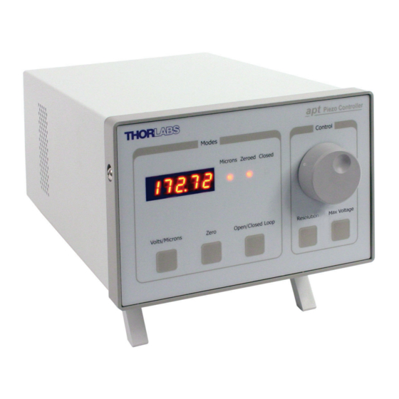
, maximum drive voltage, and zeroing of the piezo can also be selected from the front panel. Fig. 1.1 APT Single Channel Piezo Controller (BPC301) The APT piezo controller is supplied with a full suite of software support tools. An... - Page 5 Chapter 1 Overview The APT piezo unit operation is fully configurable (parameterized) with key settings exposed through the associated graphical interface panel. Open or closed loop operating modes can be selected 'on the fly', and in both modes the display can be changed to show drive voltage or position (in microns).
-
Page 6: Apt Pc Software Overview
1.2 APT PC Software Overview 1.2.1 Introduction As a member of the APT range of controllers, the BPC301 piezo controller shares many of the associated software benefits. This includes USB connectivity (allowing multiple units to be used together on a single PC), fully featured Graphical User Interface (GUI) panels, and extensive software function libraries for custom application development. -
Page 7: Aptuser Utility
Chapter 1 Overview 1.2.2 APTUser Utility The APTUser application allows the user to interact with a number of APT hardware control units connected to the host PC. This program displays multiple graphical instrument panels to allow multiple APT units to be controlled simultaneously. All basic operating parameters can be altered and, similarly, all operations (such as piezo moves) can be initiated. -
Page 8: Apt Config Utility
Single-Channel Piezo Controller, 75 V to 150 V 1.2.3 APT Config Utility There are many system parameters and configuration settings associated with the operation of the APT Server. Most can be directly accessed using the various graphical panels, however there are several system wide settings that can only be made 'off-line' before running the APT software. -
Page 9: Apt Server (Activex Controls)
With the APT system, ActiveX Controls are deployed to allow direct control over (and also reflect the status of) the range of electronic controller units, including the BPC301 piezo controller. Software applications that use ActiveX Controls are often referred to as 'client applications'. -
Page 10: Software Upgrades
APT controller. This CD contains a complete range of tutorial samples and coding hints and tips, together with handbooks for all the APT controllers. 1.2.5 Software Upgrades Thorlabs operate a policy of continuous product development and may issue software upgrades as necessary. Page 7... -
Page 11: Chaper 2 Overview
Chapter 2 Overview Chapter 2 Overview 2.1 Safety Information For the continuing safety of the operators of this equipment, and the protection of the equipment itself, the operator should take note of the Warnings, Cautions and Notes throughout this handbook and, where visible, on the product itself. The following safety symbols may be used throughout the handbook and on the equipment itself. -
Page 12: Chaper 3 Getting Started
To minimize the possibility of this happening it is strongly recommended that any such modes that result in prolonged unresponsiveness be disabled before the APT software is run. Please consult your system administrator or contact Thorlabs technical support for more details. Caution Some PCs may have been configured to restrict the users ability to load software, and on these systems the software may not install/run. -
Page 13: Mechanical Installation
Chapter 3 Getting Started 3.2 Mechanical Installation 3.2.1 Siting The unit is designed to be mounted free standing on a shelf, benchtop or similar surface. Caution When siting the unit, it should be positioned so as not to impede the operation of the rear panel power supply switch. -
Page 14: Electrical Installation
The unit must be connected only to an earthed fused supply of 85V to 264V. Use only power supply cables supplied by Thorlabs, other cables may not be rated to the same current. The unit is shipped with appropriate power cables for use in the UK, Europe and the USA. -
Page 15: Rear Panel Connections
Chapter 3 Getting Started 3.3.4 Rear Panel Connections Fig. 3.1 Rear panel connections AUX IO - This female 15-Pin D-type connector exposes a number of internal electrical signals. For convenience, a number of logic inputs and outputs are included, thereby eliminating the need for extra PC based IO hardware. - Page 16 Caution It is recommended that only cables supplied by Thorlabs are used to connect the piezo drive outputs. Other cables may not be rated to the same specification. If using third party cables for the high voltage output, the HV cable used must have insulation able to withstand 200V DC / 150V AC.
-
Page 17: Front Panel Controls And Indicators
Chapter 3 Getting Started 3.4 Front Panel Controls and Indicators The front panel controls of the BPC301 piezo controller allow the unit to be operated as a standalone unit, without the need to connect to a PC. Piezo Controller Control... -
Page 18: Button Operation
Single-Channel Piezo Controller, 75 V to 150 V Zero Button – Initiates the zeroing routine - see Section 3.5.2. Note The ‘Zero’ and ‘Open/Closed Loop’ buttons perform the same function as their respective equivalents on the software GUI panel. If a control PC is connected, pressing these buttons has the same effect as pressing the correspondingGUI button. -
Page 19: Max Voltage Button
Chapter 3 Getting Started 2) When the zeroing move has been completed, the ‘Zeroed’ LED is lit and the controller switches to closed loop mode. 3.5.3 Max Voltage Button The Max Voltage button sets the max limit of the drive output voltage. When the button is pressed and released, the present limit flahes on the main display. -
Page 20: Adjusting The Display Brightness
- see the Getting Started guide for more information 5) Run the APTUser utility Start/All Programs/Thorlabs/APT/APT User. 6) Your APT Piezo Controller is now ready for use. See the Getting Started Guide supplied with the controller or Chapter 4 of this manual, for a brief tutorial on operation of the unit. - Page 21 Chapter 3 Getting Started 3) Run the APTUser utility and check that the Graphical User Interface (GUI) panel appears and is active. Fig. 3.3 Gui panel showing jog and ident buttons 4) Click the ‘Ident’ button. The min digital display on the front panel of the controller flashes.
-
Page 22: Chaper 4 Pc Operation - Tutorial
Single-Channel Piezo Controller, 75 V to 150 V Chapter 4 PC Operation - Tutorial Warning Piezo actuators are driven by high voltages. Voltages up to 150V may be present at the SMC connector. This is hazardous and can cause serious injury. Appropriate care should be taken when using this device. - Page 23 Chapter 4 PC Operation - Tutorial 1) Run the APT User program - Start/All Programs/Thorlabs/APT User/APT User. The APT server registers automatically the units connected on the USB bus and displays the associated GUI panels as shown in Fig. 4.1.
-
Page 24: Setting The Position Sensor Zero
Single-Channel Piezo Controller, 75 V to 150 V 2) Notice how the total travel for the associated piezo is displayed in the ‘Travel’ window - see Fig. 4.2. Fig. 4.2 Piezo Controller Software GUI The APT User utility will be used throughout the rest of this tutorial to interface with the piezo controller. -
Page 25: Moving The Piezo
Chapter 4 PC Operation - Tutorial 4.4 Moving the Piezo The piezo can be manually positioned in three ways: by entering a position, by using the ‘Output’ potentiometer or by clicking the ‘Jog’ buttons. 4.4.1 Entering the piezo position Note The piezo position can be entered only when operating in ‘Closed Loop’... -
Page 26: Jogging The Piezos
Single-Channel Piezo Controller, 75 V to 150 V The ‘Output’ control is used to adjust and set the voltage or position output as displayed in the main digital display. If the channel is in closed loop mode (set using the 'closed loop' button on the panel) then this control can be used to adjust position output. -
Page 27: Using The Controller As A Piezo Amplifier
Chapter 4 PC Operation - Tutorial 5) Click the upper Jog arrow on the GUI panel to jog the piezo. Notice that the position display increments 0.1µm every time the button is clicked. 6) Click the lower Jog arrow on the GUI panel. Notice that the position display decrements 0.1µm every time the button is clicked. -
Page 28: Using The Controller With A Force Sensor
Single-Channel Piezo Controller, 75 V to 150 V condition. If the overtemp condition occurs, disconnect the load and allow 10 minutes for the unit to cool down. 4.7 Using the Controller with a Force Sensor The controller unit can also be used to control a force sensor. 1) In the GUI panel, click the ‘Settings button to display the settings panel and select the Force Sensing tab. -
Page 29: Using The Mzf001 Joystick
Chapter 4 PC Operation - Tutorial The system defaults to 'Position' (Force) display mode and the digital display shows the force detected by the sensor. The units of force are dependent upon the type of force sensor used. 4.8 Using the MZF001 Joystick The MZF001 joystick console has been designed for microscope users, to provide intuitive, tactile, manual positioning of the MZS500 stage. - Page 30 Single-Channel Piezo Controller, 75 V to 150 V Fig. 4.2 ID switch setings 3) Using a small, flathead screwdriver, set the joystick console ID switch and the controller channel ID switch as described in the preceding paragraph. Caution Do not set the switches to 'E' or 'F' as this is reserved for factory use and testing. 4) Switch ON the controller.
-
Page 31: Load Response
Chapter 4 PC Operation - Tutorial 4.9 Load Response The response of the BPC301 to varying load and frequencies is shown below. Fig. 4.8 Response of BPC301 to Varying Loads and Frequencies Page 28 Rev F Dec 2018... -
Page 32: Creating A Simulated Configuration Using Apt Config
To create a simulated configuration proceed as follows: 1) Run the APT Config utility - Start/All Programs/Thorlabs/APT/APT Config. 2) Click the 'Simulator Configuration' tab. Fig. 4.9 APT Configuration Utility - Simulator Configuration Tab 3) Enter ‘LAB1’... - Page 33 4) In the 'Simulator' field, check the ‘Enable Simulator Mode’ box. The name of the most recently used configuration file is displayed in the 'Current Configuration' window. 5) In the ‘Control Unit’ field, select ‘1 Ch Piezo Driver (BPC301)’. Page 30 Rev F Dec 2018...
- Page 34 8 digits (as displayed in the ‘Load Configuration Details’ window), the first two digits are added automatically and identify the type of control unit. The prefixed digits relating to the BPC301 piezo controller are: 41xxxxxx - Benchtop APT Single Channel Piezo Controller When the APT Software is next run up, the system automatically creates 3 simulated single channel piezo drive cards.
-
Page 35: Chaper 5 Software Reference
Fig. 5.1 BPC301 Piezo Driver Software GUI Note The serial number of the BPC301 unit associated with the GUI panel, the APT server version number, and the version number (in brackets) of the embedded software running on the unit, are displayed in the top right hand corner. This information should always be provided when requesting customer support. -
Page 36: Settings Panel
Single-Channel Piezo Controller, 75 V to 150 V Zero - used to zero the position sensor (strain gauge) when operating in 'Closed Loop mode' - see Section 5.2.4. Setting The Position Sensor Zero. Enable - enables or disables the HV channel's output voltage. With the piezo enabled, the LED in the button is lit. -
Page 37: General Tab
Chapter 5 Software Reference Guide in the APTServer helpfile (accessed via the Windows ‘Start’ menu) for further details and to Section 1.2.4. for an overview of the APT ActiveX controls). 5.2.1 General tab. Fig. 5.3 Piezo Settings panel - General tab Jog Step Size - the distance to move when a jog command is initiated. -
Page 38: Output Tab
Single-Channel Piezo Controller, 75 V to 150 V 5.2.2 Output tab. Fig. 5.4 Piezo Settings panel - General tab Output Voltage Range - the piezo actuator connected to the controller has a specific maximum operating voltage range. This parameter sets a value for the maximum output voltage;... -
Page 39: Force Sensing Tab
Chapter 5 Software Reference 5.2.3 Force Sensing tab Fig. 5.2 Piezo Settings panel - Force Sensing tab Force Sense Mode - Check this box to select Force Sensing Mode. Force Calibration - This parameter specifies the calibration factor for the type of force sensor being used. -
Page 40: Detection Of Range Of Travel
Single-Channel Piezo Controller, 75 V to 150 V In the case of actuators with position feedback, there are 4 modes of operation in total; 1) Open-loop, display voltage applied to actuator 2) Closed-loop, display position (microns) measured by sensor 3) Closed-loop, display voltage applied to actuator 4) Open-loop, display position (microns) measured by sensor Note These options can be selected through the GUI ‘Settings’... -
Page 41: Appendix A Rear Panel Connector Pinout Detail
† Power supply for the piezo actuator feedback circuit. It must not be used to drive any other circuits or devices. * This signal is applicable only to Thorlabs actuators. It enables the system to identify the piezo extension associated with the actuator. - Page 42 Single-Channel Piezo Controller, 75 V to 150 V A.2 Rear Panel AUX I/O Connector A.2.1 Pin Identification This female 15-pin D-Type connector exposes a number of internal electrical signals. For convenience, a number of logic inputs and outputs are included, thereby eliminating the need for extra PC based IO hardware.
- Page 43 Appendix A Rear Panel Connector Pinout Detail A.2.2 Digital Outputs All digital outputs are of the open-collector type, with a 330 Ohm series resistor. When the output is set to a logic zero (which is also the default state), it behaves as open circuit.
- Page 44 Single-Channel Piezo Controller, 75 V to 150 V A.2.3 Digital Inputs The digital inputs used in the controller are of the standard CMOS logic gate type with TTL compatible input levels and a built-in pull-up resistor (10 kOhm to +5V). They can be connected directly to mechanical switches, open-collector type outputs or most type of logic outputs.
- Page 45 Appendix A Rear Panel Connector Pinout Detail A.3 Rear Panel INTERCONNECT Connector Although this Male 9-Pin D-type connector exposes internal electrical signals for use with serial communications or an external remote control handset, no firmware support is available at present. The pin functions are detailed in in Fig.
-
Page 46: Appendix B Preventive Maintenance
The equipment contains no user servicable parts. There is a risk of electrical shock if the equipment is operated with the covers removed. Only personnel authorized by Thorlabs Ltd and trained in the maintenance of this equipment should remove its covers or attempt any repairs or adjustments. Maintenance is limited to safety testing and cleaning as described in the following sections. -
Page 47: Appendix C Specifications
Appendix C Specifications Appendix C Specifications C.1 Specifications Parameter Value Piezoelectric Output (SMC Male) Voltage Output 75 V, 100 V, and 150 V DC/channel Output Current 500 mA Voltage Stability 100ppm over 24 hours (after 30 mins warm up time) Noise <3m V RMS Typical Piezo Capacitance... - Page 48 Single-Channel Piezo Controller, 75 V to 150 V Parameter Value General Data Housing Dimensions (W x D x H) 152 x 244 x 104 mm (6 x 9.6 x 4.1 in.) Weight: 3.18 kg (7 lbs) * The controller measures a conditioned signal from the feedback sensor. For details of circuitry please contact Tech Support.
-
Page 49: Appendix D Piezo Control Method Summary
A brief summary of the methods and propertys applicable to the BPC301 unit is given below, for more detailed information and individual parameter descriptiond please see the on-line help file supplied with the APT server. - Page 50 Single-Channel Piezo Controller, 75 V to 150 V GetOutputLUTParams Gets the output voltage waveform (LUT) operating parameters. GetOutputLUTTrigParams Gets the output voltage waveform (LUT) triggering parameters. GetOutputLUTValue Gets a specific voltage output value in the voltage waveform (LUT) table. GetParentHWInfo Gets the identification information of the host controller.
- Page 51 Appendix D Piezo Control Method Summary SetOutputLUTTrigParams Sets the output voltage waveform (LUT) triggering parameters. SetOutputLUTValue Sets a specific voltage output value in the voltage waveform (LUT) table. SetPosOutput Sets the piezo actuator extension in closed loop mode. SetSlewRates Sets the limits for the rate of change of the drive voltage.
- Page 52 – see Fig. E.1. In this way, the distance from positive to negative electrodes is very small. A large field gradient can therefore be obtained with a modest drive voltage (75 V in the case of Thorlabs actuators). expansion piezoelectric...
- Page 53 Some Thorlabs nanopositioning actuators have position sensing, others do not. The Piezoelectric control module allows both types to be controlled.
- Page 54 Single-Channel Piezo Controller, 75 V to 150 V moving open loop control part demand actuator moving closed loop control part demand a + b/s actuator sensor Fig. E.3 Open loop and closed loop control The result of using closed-loop control is a linear relationship between demand (voltage) and measured position –...
-
Page 55: Appendix E Regulatory
Appendix F Regulatory Appendix F Regulatory F.1 Declarations Of Conformity F.1.1 For Customers in Europe See Section F.2. F.1.2 For Customers In The USA This equipment has been tested and found to comply with the limits for a Class A digital device, persuant to part 15 of the FCC rules. - Page 56 Single-Channel Piezo Controller, 75 V to 150 V F.2 CE Certificate Page 53 22882-D02...
-
Page 57: Appendix F Thorlabs Worldwide Contacts
"End of life" units must be returned to Thorlabs or handed to a company specializing in waste recovery. Do not dispose of the unit in a litter bin or at a public waste disposal site. - Page 58 www.thorlabs.com...
Need help?
Do you have a question about the BPC301 and is the answer not in the manual?
Questions and answers