
Subscribe to Our Youtube Channel
Related Manuals for THORLABS BSC202


Summary of Contents for THORLABS BSC202
- Page 1 BSC202 and BSC203 Benchtop Stepper Motor Controller User Guide Original Instructions...
-
Page 2: Table Of Contents
Contents Chapter 1 Safety ....................4 1.1 Safety Information ...................4 1.2 General Warnings ...................4 Chapter 2 Overview ..................5 2.1 Introduction .....................5 2.2 Kinesis Software Overview 7 2.2.1 Introduction ......................7 2.2.2 Kinesis Server ....................7 2.2.3 Software Upgrades .................... 9 Chapter 3 Getting Started ................10 3.1 Installing The Software .................10 3.2 Mechanical Installation ................11... - Page 3 Appendix A Rear Panel Connector Pinout Details ........40 Appendix B Using a Virtual Comm Port ............46 Appendix C Preventive Maintenance ............49 Appendix D Specifications and Associated Parts ........50 Appendix E Stepper Motor Operation - Background .........52 Appendix F Regulatory .................58 Appendix G Thorlabs Worldwide Contacts ..........61...
-
Page 4: Chapter 1 Safety
Chapter 1 Safety 1.1 Safety Information For the continuing safety of the operators of this equipment, and the protection of the equipment itself, the operator should take note of the Warnings, Cautions and Notes throughout this handbook and, where visible, on the product itself. The following safety symbols may be used throughout the handbook and on the equipment itself. -
Page 5: Chapter 2 Overview
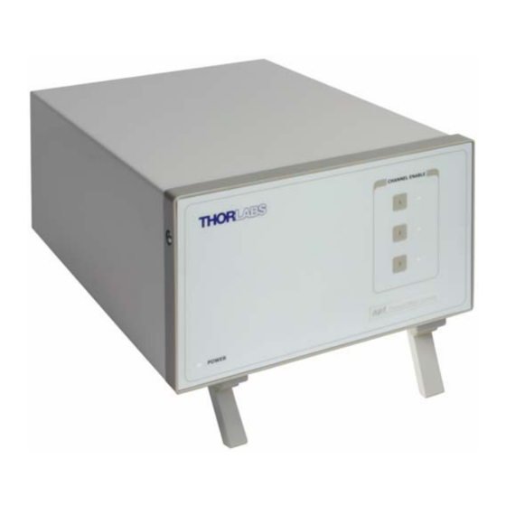
Chapter 2 Overview 2.1 Introduction The BSC202 and BSC203 are enhanced 2- and 3-channel Stepper Motor Controllers using the Kinesis software. Many features are provided, including a choice between trapezoidal and S-shaped velocity profiles, a higher theoretical microstep resolution (409600 for a 200 full step motor) and speeds more than twice that achieved by their predecessors. - Page 6 For simplicity of operation, the software incorporates pre-configured settings for each of the Thorlabs stages and actuators, while still exposing all parameters individually for use with other stepper motor driven systems.
-
Page 7: Kinesis Software Overview
2.2 Kinesis Software Overview 2.2.1 Introduction The BSC20x series share many of the benefits of the Thorlabs range of motor controllers. These include USB connectivity (allowing multiple units to be used together on a single PC), fully featured Graphical User Interface (GUI) panels, and extensive software function libraries for custom application development. - Page 8 Consider the control supplied for the BSC203 controller. This Control provides a complete user graphical instrument panel to allow the stage to be manually operated, as well as a complete set of software functions (often called methods) to allow all parameters to be set and motor operations to be automated by a client application.
-
Page 9: Software Upgrades
Kinesis Controls collection. This is available either by pressing the F1 key when running the Kinesis server, or via the Start menu, Start\Programs\Thorlabs\Kinesis\Kinesis Help. 2.2.3 Software Upgrades Thorlabs operate a policy of continuous product development and may issue software upgrades as necessary. -
Page 10: Chapter 3 Getting Started
If you experience any problems when installing software, contact Thorlabs on +44 (0)1353 654440 and ask for Technical Support. DO NOT CONNECT THE CONTROLLER TO YOUR PC YET 1) Download the software from www.thorlabs.com. -
Page 11: Mechanical Installation
Two-, and Three-Channel Stepper Motor Controller 3.2 Mechanical Installation 3.2.1 Siting The unit is designed to be mounted free standing on a shelf, benchtop or similar surface. Caution When siting the unit, it should be positioned so as not to impede the operation of the rear panel power supply switch. -
Page 12: Electrical Installation
Shock Warning The unit must be connected only to an earthed fused supply of 110 to 230V. Use only power supply cables supplied by Thorlabs, other cables may not be rated to the same current. The unit is shipped to the UK, Europe and the USA, with the appropriate power plug already fitted. -
Page 13: Rear Panel Connections
Two-, and Three-Channel Stepper Motor Controller 3.3.4 Rear Panel Connections INTERCONNECT Fig. 3.1 Rear panel connections MOTOR DRIVE - (15-Pin D-Type, Female) Provides connection to the actuator. This connector provides all phase current drive and encoder feedback connections to drive a range of encoded and non-encoded stepper motors - see Section A.3. CONTROL I/O - (15-Pin D-Type, Female) The ‘CONTROL I/O’... -
Page 14: Front Panel Controls And Indicators
LED is lit when the channel is enabled. Disabling the channel allows the motor actuator to be moved manually. Note On BSC202 units, the Channel 3 LED is not used. 3.5 Connecting The Hardware 1) Perform the mechanical installation as detailed in Section 3.2. -
Page 15: Selecting The Stage Type
Kinesis server to apply automatically, suitable default parameter values on boot up of the software. With some Thorlabs stages, the controller will recognise the stage at switch on, and no further action is required; for others, it is necessary to tell the controller which stage is connected as follows. -
Page 16: Verifying Software Operation
Chapter 3 4) Select your actuator type (e.g. HS NanoMax 300 X-Axis) from the list displayed. Note To use the increased resolution and velocity funcitionality offered by these controllers, the stage types prefixed by ‘HS’ (e.g. HS NanoMax 300) must be selected. Selecting a stage/actuator type without the ‘HS’ prefix will result in reduced velocity and resolution. -
Page 17: Chapter 4 Operation - Tutorial
Fig. 4.1 Typical User Screen 1) Run the Kinesis software - Start/All Programs/Thorlabs/Kinesis/Kinesis. Notice how the HS NanoMax 300 X Axis actuator type, selected in Section 3.6. is displayed in the ‘Settings’ window. See Section 5.3. for further details on the... -
Page 18: Homing Motors
Chapter 4 4.3 Homing Motors Homing the motor moves the actuator to the home limit switch and resets the internal position counter to zero. The limit switch provides a fixed datum that can be found after the system has been powered up. Fig. -
Page 19: Changing Motor Parameters And Moving To An Absolute Position
Two-, and Three-Channel Stepper Motor Controller 4.4 Changing Motor Parameters and Moving to an Absolute Position Absolute moves are measured in real world units (e.g. millimetres), relative to the Home position. Moves are performed using a trapezoidal or S-Curve velocity profile (see Appendix E , Section E.1.3.). -
Page 20: Jogging
Chapter 4 4.6 Jogging During PC operation, the motor actuators are jogged using the GUI panel arrow keys. There are two jogging modes available, ‘Single Step’ and ‘Continuous’. In ‘Single Step’ mode, the motor moves by the step size specified in the Step Distance parameter. -
Page 21: Setting Move Sequences
Two-, and Three-Channel Stepper Motor Controller 4.7 Setting Move Sequences The Kinesis software allows move sequences to be programmed, allowing several positions to be visited without user intervention. For more details and instructions on setting move sequences, please see the Kinesis Helpfile. 4.8 Changing and Saving Parameter Settings During operation, certain settings (e.g. -
Page 22: Using A Joystick Console
Chapter 4 4.9 Using A Joystick Console The MJC001 joystick console has been designed to provide intuitive, tactile, manual positioning of the stage. The console features a two axis joystick for XY control. Up to 3 joysticks can be connected to each other, interfacing neatly into a multi-channel control application. -
Page 23: External Triggering
Two-, and Three-Channel Stepper Motor Controller 5) Set the joystick console ID switch and the controller channel ID switches as described in the preceding paragraph. Caution Do not set the switches to identical numbers as this may result in lack of joystick control. -
Page 24: Chapter 5 Software Reference
Chapter 5 Software Reference 5.1 Introduction This chapter gives an explanation of the parameters and settings accessed from the software running on a PC. 5.2 GUI Panel The following screen shot shows the graphical user interface (GUI) (one panel per channel) displayed when accessing the controller using the Kinesis software. - Page 25 Two-, and Three-Channel Stepper Motor Controller Velocity Parameters - the present setting for the move velocity parameters and the jog step size. The travel range of the associated stage/actuator is also displayed. These settings can be adjusted as described previously, or by clicking the Settings button to display the settings window, see Section 5.3.2.
-
Page 26: Keyboard Shortcuts
Chapter 5 Stop - halts the movement of the motor. Lower Display - Shows the present state of the motor, e.g. Idle, Moving, Moving EXT or Homing. Also shows the part number of the associated actuator or stage. 5.2.1 Keyboard Shortcuts Certain functionality can also be accessed via PC keyboard shortcuts as follows: Jog Forwards ‘Ctrl’... -
Page 27: Settings Panel
Two-, and Three-Channel Stepper Motor Controller 5.3 Settings Panel When the 'Settings' button on the GUI panel is clicked, the 'Settings' window is displayed. This panel allows motor operation parameters such as move/jog velocities, and stage/axis information to be modified. Note that all of these parameters have programmable equivalents (refer to the Kinesis Server helpfile for further details. -
Page 28: Moves/Jogs Tab
Chapter 5 5.3.2 Moves/Jogs Tab Fig. 5.2 BSC20x Series Controller - Move/Jog Settings Display Units By default, the unit will display position in real world units (mm or degrees). If required, the units can be changed to so that the display shows other positional units (cm, µm, µrad etc). - Page 29 Two-, and Three-Channel Stepper Motor Controller In ‘Continuous’ mode, the motor actuator will accelerate and move at the jog velocity while the button is held down.. Fig. 5.3 Jog Modes Jog - the motor moves by the distance specified in the Step Size parameter. Continuous - the motor continues to move until the jog signal is removed (i.e.
- Page 30 Chapter 5 Backlash Distance - The system compensates for lead screw backlash during reverse direction moves, by moving passed the demanded position by a specified amount, and then reversing. This ensures that positions are always approached in a forward direction. The Backlash Distance is specified in real world units (millimeters or degrees).
- Page 31 Two-, and Three-Channel Stepper Motor Controller motion profile. The Bow Value is applied in mm/s and is derived from the Bow Index field as follows: (Bow Index -1) Bow Value = 2 within the range 1 to 262144 (Bow Index 1 to 18). In this profile mode, the acceleration increases gradually from 0 to the specified acceleration value, then decreases at the same rate until it reaches 0 again at the specified velocity.
-
Page 32: Calibration Tab
Chapter 5 5.3.3 Calibration Tab Note This section is applicable only to NRT100, NRT150, LTS150, LTS300 and MLJ050 series stages, DRV013 and DRV014 actuators. Fig. 5.6 BSC20x Series Controller - Calibration Settings Calibration enables the server to correct for any mechanical errors inherent in the system. -
Page 33: Stage/Axis Tab
Two-, and Three-Channel Stepper Motor Controller 5.3.4 Stage/Axis Tab Fig. 5.7 BSC20x Series Controller - Stage/Axis Settings Note This tab contains a number of parameters which are related to the physical characteristics of the particular stage being driven. They need to be set accordingly such that a particular stage is driven properly by the system. - Page 34 Chapter 5 Homing Settings When homing, a stage typically moves in the reverse direction, (i.e. towards the reverse limit switch). The following settings allow support for stages with both Forward and Reverse limits. Note Typically, the following two parameters are set the same, i.e. both Forward or both Reverse.
-
Page 35: Advanced Tab
Two-, and Three-Channel Stepper Motor Controller 5.3.5 Advanced Tab Fig. 5.8 Advanced Settings Encoder Settings Enabling the Encoder Settings will display another tab for use with Encoded stages. Please see the associated stage handbook for more details. Hardware Triggering Note The move parameters for triggered moves can only be set via software method calls in software. - Page 36 Chapter 5 The trigger settings can be used to configure multiple units in a master - slave set up, thereby allowing multiple channels of motion to be synchronized. Multiple moves can then be initiated via a single software or hardware trigger command. Triggers This parameter sets the trigger mode for the associated channel.
- Page 37 Two-, and Three-Channel Stepper Motor Controller For example, consider the following diagram: motor unit A CONTROL IO Pin 12 (Trigger Out) move command Motor 1 move motor unit B Triggering Parameter setup Motor Unit A (Master) CONTROL IO Pin 4 Trigger Mode - Trig Out (Trigger In) Move Type - Relative...
- Page 38 Chapter 5 steps) The moving phase powers are set automatically by the unit and cannot be adjusted. The Resting Power is entered as a percentage of full power. Note The default values applied by the software have been selected based on the type of stage or actuator associated with the motor drive.
-
Page 39: Joystick Tab
Fig. 5.10 Joystick Settings Joystick Settings If the optional Thorlabs joystick console is being used (MJC001) the following parameters are used to set the velocity and acceleration limits and the direction sense of any moves initiated from the joystick.- see Section 4.9. for more details on joystick use. -
Page 40: Appendix A Rear Panel Connector Pinout Details
Appendix A Rear Panel Connector Pinout Details A.1 Rear Panel CONTROL IO Connector The ‘CONTROL I/O’ is a 15-Pin D-Type, Female connector that exposes a number of electrical signals useful for external control. It is possible to configure a particular controller to respond to trigger inputs, generate trigger outputs or both respond to and generate a trigger output - see Section 5.3.5. - Page 41 Two-, and Three-Channel Stepper Motor Controller A.1.1 Digital/User Outputs All digital outputs are of the open-collector type, with a 330 Ohm series resistor. When the output is set to a logic zero (which is also the default state), it behaves as open circuit.
- Page 42 Appendix A A.1.2 Digital/User Inputs The digital inputs used in the controller are of the standard CMOS logic gate type with TTL compatible input levels and a built-in pull-up resistor (10 kOhm to +5V). They can be connected directly to mechanical switches, open-collector type outputs or most type of logic outputs.
- Page 43 Two-, and Three-Channel Stepper Motor Controller As this output is actively driven, it can be connected, for example, to an oscilloscope without a need for an external pull-up resistor. It can also be used to drive most optocouplers. A.1.4 Trigger Input The Trigger inputs are ekectrically identical to the digital inputs (i.e.
- Page 44 Appendix A A.1.6 +5 Volt Supply A +5 V, 250 mA supply is provided for interfacing to external circuits that require a power source. Caution Do not exceed the 250 mA maximum output current. For applications requiring higher currents an external power supply must be used. A.2 Rear Panel HANDSET Connector Provides connection to the MJC001 joystick.
- Page 45 Two-, and Three-Channel Stepper Motor Controller A.3 Rear Panel MOTOR DRIVE Connectors The ‘MOTOR DRIVE ’ is a 15-Pin D-Type, Female connector that provides connection to the motors. The pin functions are detailed in Fig. A.9. In each case the signal must be referenced to the indicated return pin in order to be true.
-
Page 46: Appendix B Using A Virtual Comm Port
Appendix B Using a Virtual Comm Port When using the low level communications protocol messages to develop client applications outside of the Kinesis software, communication with the device is facilitated by using a virtual comms port as follows: 1) Open the device manager by selecting Start/Control Panel/Device Manager/ 2) Click ‘USB Serial Bus Controllers’... - Page 47 Two-, and Three-Channel Stepper Motor Controller 3) The ‘USB Device Properties’ window is displayed. 4) Select the ‘Advanced’ tab, and check the ‘Load VCP’ box. 5) Click OK, then power cycle the device being configured.
- Page 48 Appendix B 6) In the device manager, click ‘Ports (COM & LPT)’, and note the ‘USB Device Serial Port’ COM port number (e.g. COM3). This COM port can then be used by the client application to communicate with the device using the low level protocol messages. HA0278T Rev Hk Dec 2016...
-
Page 49: Appendix C Preventive Maintenance
The equipment contains no user servicable parts. There is a risk of severe electrical shock if the equipment is operated with the covers removed. Only personnel authorized by Thorlabs Ltd and trained in the maintenance of this equipment should remove its covers or attempt any repairs or adjustments. -
Page 50: Appendix D Specifications And Associated Parts
Appendix D Specifications and Associated Parts D.1 Specifications Parameter Value Input/Output Motor Drive 2-Phase Bipolar Motor Drive Output (15-Pin D-type Female) Differential Quadrature Encoder Interface Forward, Reverse Limit Switch Inputs Control IO Jog Forward (15-Pin D-type Female) Jog Back User Outputs/Inputs Single - ended analog input (0-10 Volt) Trigger In/Out Resolution... - Page 51 Two-, and Three-Channel Stepper Motor Controller D.2 Associated Products Product Name Part Number Stepper Motor Actuator, 4mm travel DRV001 Stepper Motor Actuator, 25mm (1”) travel, trapezoidal leadscrew DRV013 Stepper Motor Actuator, 50mm (2”) travel, trapezoidal leadscrew DRV014 Stepper Motor Drive Cable (1.25 Metres) PAA 610 Stepper Motor Drive Cable (3.0 Metres) PAA 611...
-
Page 52: Appendix E Stepper Motor Operation - Background
E.1 How A Stepper Motor Works E.1.1 General Principle Thorlabs’ actuators use a stepper motor to drive a precision lead screw. Stepper motors operate using the principle of magnetic attraction and repulsion to convert digital pulses into mechanical shaft rotation. The amount of rotation achieved is directly proportional to the number of input pulses generated and the speed is proportional to the frequency of these pulses. - Page 53 Two-, and Three-Channel Stepper Motor Controller E.1.2 Positive and Negative Moves Positive and negative are used to describe the direction of a move. A positive move means a move from a smaller absolute position to a larger one, a negative move means the opposite.
- Page 54 Appendix E The S-curve profile is a trapezoidal curve with an additional 'Bow Value' parameter, which limits the rate of change of acceleration and smooths out the contours of the motion profile. The Bow Value is applied in mm/s and is derived from the Bow Index field as follows: (Bow Index -1) Bow Value = 2...
- Page 55 Two-, and Three-Channel Stepper Motor Controller conversion is performed internally by the controller. If operating via a PC (remote mode) then the conversion is performed by the Kinesis software. Each motor in the system has an associated electronic counter in the controller, which keeps a record of the net number of microsteps moved.
- Page 56 Appendix E E.2.4 Minimum and Maximum Positions These positions are dependent upon the stage or actuator to which the motors are fitted, and are defined as the minimum and maximum useful positions of the stage relative to the ‘Home’ position - see Fig. E.5. The distance from the Minimum position to the Maximum position is the ‘useful travel’...
- Page 57 Two-, and Three-Channel Stepper Motor Controller E.3 Error Correction E.3.1 Backlash correction The term backlash refers to the tendency of the stage to reach a different position depending on the direction of approach. Backlash can be overcome by always making the last portion of a move in the same direction, conventionally the positive direction.
-
Page 58: Appendix F Regulatory
Appendix F Regulatory F.1 Declarations Of Conformity F.1.1 For Customers in Europe See Section F.3. F.1.2 For Customers In The USA This equipment has been tested and found to comply with the limits for a Class A digital device, persuant to part 15 of the FCC rules. These limits are designed to provide reasonable protection against harmful interference when the equipment is operated in a commercial environment. - Page 59 • left over parts of units disassembled by the user (PCB's, housings etc.). If you wish to return a unit for waste recovery, please contact Thorlabs or your nearest dealer for further information. F.2.2 Waste treatment on your own responsibility If you do not return an "end of life"...
- Page 60 Appendix F F.3 CE Certificates HA0278T Rev Hk Dec 2016...
-
Page 61: Appendix G Thorlabs Worldwide Contacts
Two-, and Three-Channel Stepper Motor Controller Appendix G Thorlabs Worldwide Contacts For technical support or sales inquiries, please visit us at www.thorlabs.com/contact for our most up-to-date contact information. USA, Canada, and South America UK and Ireland Thorlabs, Inc. Thorlabs Ltd. - Page 62 www.thorlabs.com...
Need help?
Do you have a question about the BSC202 and is the answer not in the manual?
Questions and answers