Table of Contents
Advertisement
Quick Links
Advertisement
Table of Contents

Related Manuals for THORLABS BPC203


Summary of Contents for THORLABS BPC203
- Page 1 BPC203 Benchtop Piezo Controller User Guide...
-
Page 2: Table Of Contents
Contents Chapter 1 Safety ..................... 4 1.1 Safety Information .................. 4 1.2 General Warnings .................. 4 Chapter 2 Overview..................5 2.1 Introduction ..................... 5 2.2 APT PC Software Overview ..............7 2.2.1 Introduction ......................7 2.2.2 APTUser Utility ....................8 2.2.3 APT Config Utility .................... - Page 3 Appendix B Preventive Maintenance ............43 Appendix C Specifications and Associated Parts ........44 Appendix D Piezo Control Method Summary ..........46 Appendix E Piezo Operation - Background ..........49 Appendix F Regulatory ................52 Appendix G Thorlabs Worldwide Contacts ..........55...
-
Page 4: Chapter 1 Safety
Chapter 1 Safety 1.1 Safety Information For the continuing safety of the operators of this equipment, and the protection of the equipment itself, the operator should take note of the Warnings, Cautions and Notes throughout this handbook and, where visible, on the product itself. The following safety symbols may be used throughout the handbook and on the equipment itself. -
Page 5: Chapter 2 Overview
These high power units deliver up to 75V/500mA per channel and are compatible with all piezo-actuated nanopositioning actuators & stages in the Thorlabs range. The unit combines the latest highspeed digital signal processors (DSP) with low-noise analog electronics and ActiveX®... - Page 6 Chapter 2 operating modes can be selected 'on the fly', and in both modes the display can be changed to show drive voltage or position (in microns). In the closed loop operation mode, both the P & I (proportional and integral) components of the feedback control loop can be altered to adjust the servoloop response.
-
Page 7: Apt Pc Software Overview
2.2 APT PC Software Overview 2.2.1 Introduction As a member of the APT range of controllers, the BPC202 and BPC203 piezo controllers share many of the associated software benefits. This includes USB connectivity (allowing multiple units to be used together on a single PC), fully featured Graphical User Interface (GUI) panels, and extensive software function libraries for custom application development. -
Page 8: Aptuser Utility
Chapter 2 2.2.2 APTUser Utility The APTUser application allows the user to interact with a number of APT hardware control units connected to the host PC. This program displays multiple graphical instrument panels to allow multiple APT units to be controlled simultaneously. All basic operating parameters can be altered and, similarly, all operations (such as piezo moves) can be initiated. -
Page 9: Apt Config Utility
Three-Channel Piezo Controller 2.2.3 APT Config Utility There are many system parameters and configuration settings associated with the operation of the APT Server. Most can be directly accessed using the various graphical panels, however there are several system wide settings that can only be made 'off-line' before running the APT software. -
Page 10: Apt Server (Activex Controls)
Basic, Labview, Visual C++, C++ Builder, HPVEE, Matlab, VB.NET, C#.NET and, via VBA, Microsoft Office applications such as Excel and Word. Consider the ActiveX Control supplied for a Piezo Drive Card fitted to a BPC203 APT piezo controller unit (one panel is displayed for each channel (card) fitted). -
Page 11: Software Upgrades
APT controllers. 2.2.5 Software Upgrades Thorlabs operate a policy of continuous product development and may issue software upgrades as necessary. Detailed instructions on installing upgrades are included on the APT Software... -
Page 12: Chapter 3 Set Up
If you experience any problems when installing software, contact Thorlabs on +44 (0)1353 654440 and ask for Technical Support. DO NOT CONNECT THE CONTROLLER TO YOUR PC YET 1) Insert the CD into your PC. -
Page 13: Mechanical Installation
The unit must be connected only to an earthed fused supply of 110 to 230V. Use only power supply cables supplied by Thorlabs, other cables may not be rated to the same current. The unit is shipped with appropriate power cables for use in the UK, Europe and the USA. -
Page 14: Fuses
Chapter 3 3.3.2 Fuses Two T 3A/250V a.c. antisurge ceramic fuses are located on the back panel, one for the live feed and one for the neutral. When replacing fuses: 1) Switch off the power and disconnect the power cord before removing the fuse cover. - Page 15 Three-Channel Piezo Controller RS232/HANDSET - Provides connection for a remote handset (PHS101) or serial port communication - see Section A.3. for further details. USER I/O - The User I/O connector exposes a number of internal electrical signals. For convenience, a number of logic inputs and outputs are included, thereby eliminating the need for extra PC based IO hardware.
-
Page 16: Front Panel Controls And Indicators
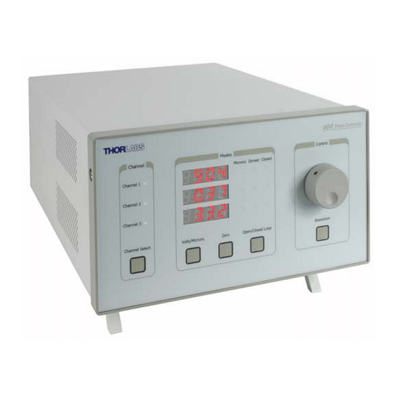
Chapter 3 3.4 Front Panel Controls and Indicators The front panel controls of the BPC203 piezo controller allow the unit to be operated as a standalone unit, without the need to connect to a PC. Piezo Controller Control Channel Modes... -
Page 17: Button Operation
Three-Channel Piezo Controller Zero Button – Initiates the zeroing routine - see Section 3.5.2. Note The ‘Zero’ and ‘Open/Closed Loop’ buttons perform the same function as their respective equivalents on the software GUI panel. If a control PC is connected, pressing these buttons has the same effect as pressing the correspondingGUI button. -
Page 18: Control Potentiometer Operation
Chapter 3 3.6 Control Potentiometer Operation The ‘Control’ potentiometer is an infinite turn encoder, used to adjust and set the voltage or position output as displayed in the main digital display. To increase the drive voltage, turn the potentiometer clockwise - once the maximum voltage (75V) is attained, subsequent clockwise turns do not effect the output, however the voltage decreases immediately the control is turned anticlockwise. -
Page 19: Connecting The Hardware
- see the Getting Started guide for more information 4) Run the APTUser utility Start/Programs/Thorlabs/APT/APT User. 5) Your APT Piezo Controller is now ready for use. See the Getting Started Guide supplied with the controller, or Chapter 4 of this manual, for a brief tutorial on operation of the unit. - Page 20 Chapter 3 3) Click the ‘Ident’ button. The associated channel LED on the front panel of the controller flashes. This is useful in multi-channel systems for identifying which channel is associated with which GUI. 4) Click the jog buttons on the GUI panel to move the piezo or axis connected to the controller.
-
Page 21: Chapter 4 Pc Operation - Tutorial
Chapter 4 PC Operation - Tutorial 4.1 Introduction The following brief tutorial guides the user through a typical series of actions and parameter adjustments performed using the PC based APT software. It assumes that the unit is electrically connected as shown in Section 3.3.4. and that the APT Software is already installed - see Section 3.1. - Page 22 GUI panels as shown in Fig. 4.1. Fig. 4.1 Typical APT User Screen Note The BPC203 APT piezo controller unit can be fitted with up to three PCC101 piezo drive cards. Each card behaves as a discrete unit with its own GUI control panel.
-
Page 23: Setting The Position Sensor Zero
Three-Channel Piezo Controller 2) Notice how the total travel for the associated piezo is displayed in the ‘Travel’ window - see Fig. 4.2. Fig. 4.2 Piezo Controller Software GUI The APT User utility will be used throughout the rest of this tutorial to interface with the piezo controller. -
Page 24: Moving The Piezo
Chapter 4 4.4 Moving the Piezo The piezo can be manually positioned in three ways: by entering a position, by using the ‘Output’ potentiometer or by clicking the ‘Jog’ buttons. 4.4.1 Entering the piezo position Note The piezo position can be entered only when operating in ‘Closed Loop’ mode. -
Page 25: Moving The Piezo Using The 'Output' Control
Three-Channel Piezo Controller 4.4.2 Moving the Piezo using the ‘Output’ control The ‘Output’ control is used to adjust and set the voltage or position output as displayed in the main digital display. If the channel is in closed loop mode (set using the 'closed loop' button on the panel) then this control can be used to adjust position output. -
Page 26: Using The Controller As A Piezo Amplifier
Chapter 4 3) In the ‘Jog Step Size’ field, enter 0.1 4) Click ‘OK’ to save the settings and close the window. 5) Click the upper Jog arrow on the GUI panel to jog the piezo. Notice that the position display increments 0.1µm every time the button is clicked. 6) Click the lower Jog arrow on the GUI panel. -
Page 27: Thermal Shutdown
Three-Channel Piezo Controller 4.6 Thermal Shutdown In order to protect the piezo driver card from overheating due to abnormal load conditions, the electronics contains thermal protection circuitry. When the protection is activated, the HV output its shut down, limiting the maximum output current to a few milliamps, and the ‘Error’... - Page 28 Chapter 4 In Force Sensor mode, an 'F' is displayed next to the digital display on the GUI panel. Fig. 4.7 GUI Display - Force Sensor Mode The system defaults to 'Position' (Force) display mode and the digital display shows the force detected by the sensor.
-
Page 29: Creating A Simulated Configuration Using Apt Config
To create a simulated configuration proceed as follows: 1) Run the APT Config utility - Start/All Programs/Thorlabs/APT/APT Config. 2) Click the 'Simulator Configuration' tab. Fig. 4.8 APT Configuration Utility - Simulator Configuration Tab... - Page 30 4) In the 'Simulator' field, check the ‘Enable Simulator Mode’ box. The name of the most recently used configuration file is displayed in the 'Current Configuration' window. 5) In the ‘Control Unit’ field, select ‘3 Ch Piezo Driver (BPC203)’. HA0138T Rev 7 June 2011...
- Page 31 The prefixed digits relating to the BPC203 piezo controller are: 71xxxxxx - Benchtop APT Single Channel Piezo Controller When the APT Software is next run up, the system automatically creates 3 simulated single channel piezo drive cards.
-
Page 32: Chapter 5 Software Reference
Chapter 5 Software Reference 5.1 GUI Panel The following screen shot shows the graphical user interface (GUI) (one panel per card fitted) displayed when accessing the controller using the APTUser utility. Fig. 5.1 PCC101 Piezo Driver Software GUI Note The serial number of the PCC101 card associated with the GUI panel, the APT server version number, and the version number (in brackets) of the embedded software running on the unit, are displayed in the top right hand corner. - Page 33 Three-Channel Piezo Controller Travel - the range of travel (in µm) of the piezo actuator. Zero - used to zero the position sensor (strain gauge) when operating in 'Closed Loop mode' - see Section 5.2.3. Setting The Position Sensor Zero. Enable - enables or disables the HV channel's output voltage.
-
Page 34: Settings Panel
Chapter 5 5.2 Settings Panel When the 'Settings' button on the GUI panel is clicked, the 'Settings' window is displayed. This panel allows data such as jog step size and input sources to be entered. Note that all of these parameters have programmable equivalents accessible through the ActiveX methods and properties on this Control (refer to the Programming Guide in the APTServer helpfile (accessed via the Windows ‘Start’... -
Page 35: Force Sensing Tab
Three-Channel Piezo Controller 5.2.2 Force Sensing tab Fig. 5.2 Piezo Settings panel - Force Sensing tab Force Sense Mode - Check this box to select Force Sensing Mode. Force Calibration - This parameter specifies the calibration factor for the type of force sensor being used. -
Page 36: Detection Of Range Of Travel
Chapter 5 1) Open-loop, display voltage applied to actuator 2) Closed-loop, display position (microns) measured by sensor 3) Closed-loop, display voltage applied to actuator 4) Open-loop, display position (microns) measured by sensor. Note These options can be selected through the GUI ‘Settings’ panel or by calling the SetVoltPosDispMode method from the application software. -
Page 37: Appendix A Rear Panel Connector Pinout Details
† Power supply for the piezo actuator feedback circuit. It must not be used to drive any other circuits or devices. * This signal is applicable only to Thorlabs actuators. It enables the system to identify the piezo extension associated with the actuator. - Page 38 Appendix A A.2 Rear Panel User I/O Connector A.2.1 Pin Identification The User I/O connector exposes a number of internal electrical signals. For convenience, a number of logic inputs and outputs are included, thereby eliminating the need for extra PC based IO hardware. Using the APT support software, these user programmable logic lines can be deployed in applications requiring control of external devices such a relays, light sources and other auxilliary equipment.
- Page 39 Three-Channel Piezo Controller A.2.2 Digital Outputs All digital outputs are of the open-collector type, with a 330 Ohm series resistor. When the output is set to a logic zero (which is also the default state), it behaves as open circuit. When it is a logic one, it behaves as a 330 Ohm resistor connected to ground. 330R Output Fig.
- Page 40 Appendix A A.2.3 Digital Inputs The digital inputs used in the controller are of the standard CMOS logic gate type with TTL compatible input levels and a built-in pull-up resistor (10 kOhm to +5V). They can be connected directly to mechanical switches, open-collector type outputs or most type of logic outputs.
- Page 41 Three-Channel Piezo Controller As this output is actively driven, it can be connected, for example, to an oscilloscope without a need for an external pull-up resistor. It can also be used to drive most optocouplers. A.2.5 Trigger Input The Trigger inputs are electrically identical to the digital inputs (i.e. a standard CMOS logic gate type with TTL compatible input levels and a built-in pull-up resistor, 10 kOhm to +5V).
- Page 42 A.3 Rear Panel RS232/HANDSET Connector A.3.1 Pin Identification The RS232/HANDSET connector exposes internal electrical signals for use with serial communications or an external remote control handset, e.g. Thorlabs PHS101 Remote Handset. The pin functions are detailed in in Fig. A.8 .
-
Page 43: Appendix B Preventive Maintenance
The equipment contains no user servicable parts. There is a risk of electrical shock if the equipment is operated with the covers removed. Only personnel authorized by Thorlabs Ltd and trained in the maintenance of this equipment should remove its covers or attempt any repairs or adjustments. Maintenance is limited to safety testing and cleaning as described in the following sections. -
Page 44: Appendix C Specifications And Associated Parts
Appendix C Specifications and Associated Parts C.1 Specifications Parameter Value Piezoelectric Output Connector Type SMC Male Voltage Output 0 to 75 V DC/channel Voltage Stability 100ppm over 24 hours (after 30 mins warm up time) Noise <3m V RMS Output Current 500mA/channel Strain Gauge Position Feedback (per channel) Feedback... - Page 45 Three-Channel Piezo Controller C.2 Associated Products Part Product Name Number Drive Cable for Piezoelectric Actuators (3.0 m) PAA100 Drive Cable Extension for Piezo Actuators (3.0 m) PAA100A Drive Cable for Piezoelectric Actuators (1.5 m) PAA101 Drive Cable Extension for Piezo Actuators (1.5 m) PAA101A Feedback Cable for Piezoelectric Actuators (1.0 m) PAA605...
-
Page 46: Appendix D Piezo Control Method Summary
A brief summary of the methods and propertys applicable to the BPC203 unit is given below, for more detailed information and individual parameter descriptiond please see the on-line help file supplied with the APT server. - Page 47 Three-Channel Piezo Controller GetOutputLUTTrigParams Gets the output voltage waveform (LUT) triggering parameters. GetOutputLUTValue Gets a specific voltage output value in the voltage waveform (LUT) table. GetParentHWInfo Gets the identification information of the host controller. GetPosOutput Gets the piezo actuator extension in closed loop mode.
- Page 48 Appendix D SetVoltOutput Sets the HV output voltage. SetVoltPosDispMode Sets the GUI display mode (voltage or position). ShowEventDialog Shows the event dialog when it has previously been disabled using the EnableEventDlg method StartCtrl Starts the ActiveX Control (starts communication with controller) StartOutputLUT Starts outputting the voltage waveform (LUT).
-
Page 49: Appendix E Piezo Operation - Background
– see Fig. E.1. In this way, the distance from positive to negative electrodes is very small. A large field gradient can therefore be obtained with a modest drive voltage (75 V in the case of Thorlabs actuators). expansion piezoelectric... - Page 50 Some Thorlabs nanopositioning actuators have position sensing, others do not. The Piezoelectric control module allows both types to be controlled.
- Page 51 Three-Channel Piezo Controller moving open loop control part demand actuator moving closed loop control part demand a + b/s actuator sensor Fig. E.3 Open loop and closed loop control The result of using closed-loop control is a linear relationship between demand (voltage) and measured position –...
-
Page 52: Appendix F Regulatory
Appendix F Regulatory F.1 Declarations Of Conformity F.1.1 For Customers in Europe This equipment has been tested and found to comply with the EC Directives 89/336/EEC ‘EMC Directive’ and 73/23/EEC ‘Low Voltage Directive’ as amended by 93/68/EEC. Compliance was demonstrated by conformance to the following specifications which have been listed in the Official Journal of the European Communities: Safety EN61010: 2001 Installation Category II, Polution Degree II. - Page 53 OEM laser driver cards) • components • mechanics and optics • left over parts of units disassembled by the user (PCB's, housings etc.). If you wish to return a unit for waste recovery, please contact Thorlabs or your nearest dealer for further information.
- Page 54 Appendix F F.2.2 Waste treatment on your own responsibility If you do not return an "end of life" unit to the company, you must hand it to a company specialized in waste recovery. Do not dispose of the unit in a litter bin or at a public waste disposal site.
-
Page 55: Appendix G Thorlabs Worldwide Contacts
UK and Ireland Thorlabs, Inc. Thorlabs Ltd. sales@thorlabs.com sales.uk@thorlabs.com techsupport@thorlabs.com techsupport.uk@thorlabs.com Europe Scandinavia Thorlabs GmbH Thorlabs Sweden AB europe@thorlabs.com scandinavia@thorlabs.com France Brazil Thorlabs SAS Thorlabs Vendas de Fotônicos Ltda. sales.fr@thorlabs.com brasil@thorlabs.com Japan China Thorlabs Japan, Inc. Thorlabs China sales@thorlabs.jp chinasales@thorlabs.com... - Page 56 Thorlabs Inc. Thorlabs Ltd. 435 Route 206 North Saint Thomas Place, Ely Newton, NJ07860 Cambridgeshire CB7 4EX, Tel: +1 973 579 7227 Tel: +44 (0) 1353 654440 Fax: +1 973 300 3600 Fax: +44 (0) 1353 654444 www.thorlabs.com www.thorlabs.com...
Need help?
Do you have a question about the BPC203 and is the answer not in the manual?
Questions and answers