Table of Contents
Advertisement
Quick Links
Advertisement
Table of Contents

Related Manuals for THORLABS BSC201


Summary of Contents for THORLABS BSC201
- Page 1 BSC201 Benchtop Stepper Motor Controller User Guide Original Instructions...
-
Page 2: Table Of Contents
Appendix D Specifications and Associated Products ......56 Appendix E Motor Control Method Summary ..........58 Appendix F Stepper Motor Operation - Background ........ 62 Appendix G Regulatory ................68 Appendix H Thorlabs Worldwide Contacts ..........71 HA0277T Rev H Dec 2016... -
Page 3: Chapter 1 Safety
To minimize the possibility of this happening it is strongly recommended that any such modes that result in prolonged unresponsiveness be disabled before the APT software is run. Please consult your system administrator or contact Thorlabs technical support for more details. -
Page 4: Chapter 2 Overview
Chapter 2 Overview 2.1 Introduction The BSC201 single channel APT Stepper Motor Controller is the next generation of enhanced controllers using the familiar APTUser interface. Many new fe atures are provided, including a choice between trapezoidal and S-shaped velocity profiles, a higher theoretical microstep resolution (409600 for a 200 full step motor) and speeds more than twice that achieved by its predecessors. -
Page 5: Apt Pc Software Overview
2.2 APT PC Software Overview 2.2.1 Introduction As a member of the APT range of controllers, the BSC201 stepper controller shares many of the associated software benefits. This includes USB connectivity (allowing multiple units to be used together on a single PC), fully featured Graphical User Interface (GUI) panels, and extensive software f unction libraries for custom application development. - Page 6 Chapter 2 automated positioning applications very rapidly and with great ease. The APT server is described in more detail in Section 2.2.4. Aside ActiveX®, a Windows®-based, language-independent technology, allows a user to quickly develop custom applications that automate the control of APT system hardware units.
- Page 7 Single Channel Stepper Motor Controller software. For those who d o need to furth er customise an d automate usage of the controller (e.g. to implement a positioning algorithm), this application illustrates how the rich functionality provided by the APT ActiveX server i s exposed by a client application.
- Page 8 With the APT system, ActiveX Controls are deployed to allow direct control over (and also reflect the status of) the range of electronic controller units, including the BSC201 stepper motor controller. Software applications that use ActiveX Controls are often referred to as 'client applications'.
- Page 9 APT controllers. 2.2.5 Software Upgrades Thorlabs operate a policy of continuous product development and may issue software upgrades as necessary. Detailed instructions on installing upgrades are included on the APT Software...
-
Page 10: Chapter 3 Getting Started
To minimize the possibility of this happening it is strongly recommended that any such modes that result in prolonged unresponsiveness be disabled before the APT software is run. Please consult your system administrator or contact Thorlabs technical support for more details. Caution Some PCs may have been configured to restrict the users ability to load software, and on these systems the software may not install/run. -
Page 11: Mechanical Installation
Single Channel Stepper Motor Controller 3.2 Mechanical Installation 3.2.1 Siting The BSC201 is designed to be mounted free standing on a shelf, benchtop or similar surface. Caution When siting the unit, it should be positioned so as not to impede the operation of the rear panel power supply switch or the control panel buttons. -
Page 12: Electrical Installation
Shock Warning The unit must be connected only to an earthed fused supply of 110 to 230V. Use only power supply cables supplied by Thorlabs, other cables may not be rated to the same current. The unit is shipped to the UK, Europe and the USA, with the appropriate power plug already fitted. - Page 13 Single Channel Stepper Motor Controller 3.3.4 Rear Panel Connections Fig. 3.1 Rear panel connections USB - USB port for system communications. Note The USB cable length should be no more than 3 metres unless a powered USB hub is being used. HANDSET IN - Provides connection for the MJC001 Joystick - see Section 4.10.
-
Page 14: Front Panel Controls And Indicators
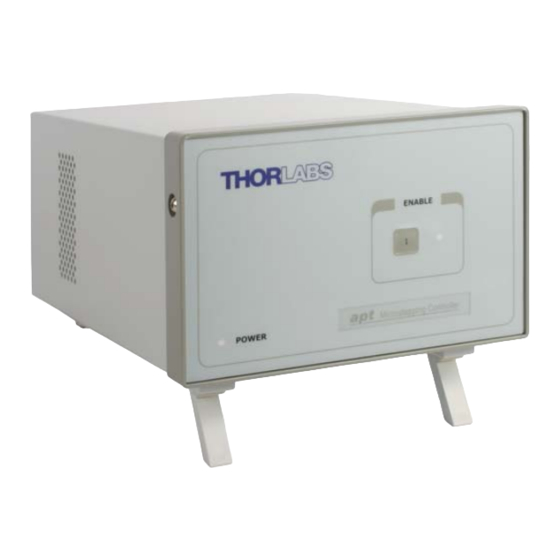
Chapter 3 3.4 Front Panel Controls and Indicators ENABLE Precision Motion Controller Power Fig. 3.2 Front panel controls and indicators Power LED – Indicates that power is applied to the unit. Enable button – Used to enable/disable channel functionality. The associated LED is lit when the channel is enabled. -
Page 15: Select The Stage Type (Using Aptconfig)
1) Shut down all applications using the APT server (e .g. APT User or your own custom application). 2) Run the APT Config utility - Start/All Programs/Thorlabs/APT Config/APT Config. 3) From the 'APT Configuration Utility' window, click the 'Stage' tab. - Page 16 Chapter 3 4) In the ‘Motor’ field, select the serial number of the stepper motor controller to be configured (this number can be found on the rear panel of the BSC201 unit). Note To use the increased resolution and velocity funcitionality offered by these controllers, the stage types prefixed by ‘HS’...
-
Page 17: Verifying Software Operation
Single Channel Stepper Motor Controller 3.7 Verifying Software Operation 3.7.1 Initial Setup The APT Software should be installed (Section 3.1.) and the stage association performed (Section 3.6.) before software operation can be verified. 1) Run the APTUser utility and check that the Graphical User Interface (GUI) panel appears and is active. -
Page 18: Chapter 4 Operation - Tutorial
Hardware configurations and parameter settings can be save d to a file , which simplifies system set up whenever APT User is run up. Fig. 4.1 Typical APT User Screen 1) Run the APT User program - Start/All Programs/Thorlabs/APT User/APT User. -
Page 19: Homing Motors
Single Channel Stepper Motor Controller 4.3 Homing Motors Homing the motor moves the actuator to the home limit switch and resets the internal position counter to zero. The limit switch provides a fixed datum that can be found after the system has been powered up. Fig. -
Page 20: Moving To An Absolute Position
Chapter 4 4.4 Moving to an Absolute Position Absolute moves are mea sured in real world units (e.g. millimetres), relative to the Home position. 1) Click the position display. Fig. 4.3 Absolute Position Popup Window 2) Enter 3.0 into the pop up window 3) Click ‘OK’. -
Page 21: Changing Motor Parameters
Single Channel Stepper Motor Controller 4.6 Changing Motor Parameters Note Moves are performed using a Trapezoidal or S-Curve velocity profile (see Appendix F , Section F.1.3.). The velocity settings relate to the maximum velocity at which a move is performed, and the acceleration at which the motor speeds up from zero to maximum velocity. -
Page 22: Jogging
Chapter 4 4.7 Jogging During PC operation, the motor actuators are jogged using the GUI panel arrow keys. There are two jogging modes available, ‘Single Step’ and ‘Continuous’. In ‘Single Step’ mode, the motor moves by the ste p size specifie d in the Ste p Distance parameter. -
Page 23: Graphical Control Of Motor Positions (Point And Move)
Note For single channel units such as the BSC201, the Channel 2 parameters are greyed out. The left h and display shows a circle , which represents the current position of the motor associated with the specified controller (absolute position data is displayed in the 'Chan Pos' field). - Page 24 Chapter 4 Move Mode When ‘Move’ is selected, the motors move to an absolute position which corresponds to the position of the cursor within the screen. To specify a move: 1) Position the mouse within the window. For reference, the absolute motor position values associated with the mouse position is d isplayed in the ' Cursor Position field.
-
Page 25: Setting Move Sequences
Single Channel Stepper Motor Controller 4.9 Setting Move Sequences This section explains how to set move sequences, allowing several positions to be visited without user intervention. For details on moving to absolute positions initiated by a mouse click – see Section 4.12. - Page 26 Chapter 4 3) Select 'New' to display the 'Move Editor' panel. Fig. 4.9 Move Editor Window Move data is entered/displayed as follows: Dist/Pos: - the distance to move from the current position (if 'Relative' is selected) or the position to move to (if 'Absolute' is selected). Dwell Time: - after the move is performed, th e system can be set to wait for a specified time before performing the next move in the sequence.
- Page 27 Single Channel Stepper Motor Controller 4) Enter the required move data into the Move Editor and click OK. The move data is displayed in the main window as shown below. Fig. 4.10 Main Window with Move Data 5) Repeat step 4 as n ecessary to b uild a sequence of moves. Move data can be copied, deleted, cut/pasted and edited by righ t clicking the data line(s) and selecting the appropriate option in the pop up menu (shown below).
-
Page 28: Using A Joystick Console
In order for the controller and joystick to be used without a host PC, the Move/ Jog settings, Stage/Axis settings and the Joystick settings must be persisted (saved) within the BSC201 unit before the following predure is performed. This is done by checking the ‘Persist Settings’ box on each settings tab - see Section 5.3. -
Page 29: Creating A Simulated Configuration Using Apt Config
For example, an application program can be w ritten, then tested and debugged remotely, before running with the hardware. To create a simulated configuration proceed as follows: 1) Run the APT Config utility - Start/All Programs/Thorlabs/APT/APT Config. - Page 30 Chapter 4 2) Click the 'Simulator Configuration' tab. Fig. 4.13 APT Configuration Utility - Simulator Configuration Tab 3) Enter ‘LAB1’ in the Configuration Names field. 4) In the 'Simulator' field, check the ‘Enable Simulator Mode’ box. The name of the most recently used configuration file is d isplayed in the 'Current Configuration' window.
- Page 31 Single Channel Stepper Motor Controller 5) In the ‘Control Unit’ field, select ‘1 Ch Stepper Driver (BSC201)’. 6) Enter a 6 digit serial number. Note Each physical APT hardware unit is factory programmed with a unique 8 digit serial number. In order to simulate a set of ‘real’ hardware the Config utility allows an 8 digit serial number to be associated with each simulated unit.
-
Page 32: Stage/Axis Tab
APTUser. These parameters should not be altered for pre-defined Thorlabs stages and actuators sel ected using APT Config, as it may a dversely affect the performance of the stage. -
Page 33: Chapter 5 Software Reference
Fig. 5.1 Motor Controller Software GUI Note The serial number of the BSC201 controller associated with the GUI panel, the APT server version number, and the version number (in brackets) of the embedded software running on the unit, are displayed in the top right hand corner. - Page 34 Chapter 5 Travel - displays the range of travel (in millimeters or degrees) of the motor. Moving - lit when the motor is in motion. Enable - applies power to the motor. With the motor enabled, the associated Channel LED on the front panel is lit. Digital display - sh ows the po sition (in millimetres or degrees) of th e motor.
-
Page 35: Settings Panel
Single Channel Stepper Motor Controller 5.3 Settings Panel When the 'Settings' button on th e GUI pan el is clicked, the 'Settings' window is displayed. This panel allows motor operation parameters such as move/jog velocities, and stage/axis information to be modified. Note that all of th ese parameters have programmable equivalents accessible through the ActiveX methods an d properties on this Control (refer to the Programming Guide in the APTServer helpfile for further details and to Section 2.2.4. - Page 36 Chapter 5 Jogs Jogs are initiated by using the ‘Jog’ keys on the GUI panel (see Section 4.7.), or via a jog handset connected to the Input logic pins exposed on the rear panel Control IO connector (see Appendix A Velocity Profile (specified in real world units, millimetres or degrees) MaxVel - the maximum velocity at which to perform a jog Accn/Dec - the ra te at which the ve locity climbs from m inimum to maximum, and...
- Page 37 Single Channel Stepper Motor Controller Step Distance - The distance to move when a jog command is initiated. The step size is specified in real world units (mm or degrees dependent upon the stage). Backlash Correction - The system c ompensates for lead scre w backlash during reverse direction moves, by moving passed the demanded position by a specified amount, and then reversing.
- Page 38 Chapter 5 The S-curve profile is a trapezoidal curve with an additional 'Bow Value' parameter, which limits the rate of change of acceleration and smooths out the contours of the motion profile. The Bow Value is applied in mm/s and is derived from the Bow Index field as follows: (Bow Index -1) Bow Value = 2...
- Page 39 Single Channel Stepper Motor Controller Persist Settings to Hardware - Many of the parameters that can be set for the BSC201 series drivers can be stored (persisted) within the unit itself, such that when the unit is next powered up th ese settings are applied automatically. This is particularly important when the driver is being used manually via a joystick, in the a bsence of a PC and USB l ink.
- Page 40 Chapter 5 Stage and Axis Type - For Thorlabs stages, the stage type is displayed automatically once the axis has been associated using the APTConfig utility. For third party stages, the display shows ‘Unknown’. Caution Extreme care must be taken when modifying the stage related settings that follow.
- Page 41 ‘Steps Per Rev’ parameter is entered as full steps, not microsteps. The system automatically applies a factor of 128 microsteps per full step. The stepper motors used on the majority of Thorlabs stages/actuators have 200 full steps per rev and no gearbox fitted. For these motors the Steps Per Rev and Gearbox Ratio parameters have values of 200 and 1 respectively.
- Page 42 Chapter 5 Persist Settings to Hardware - Many of the par ameters that can be set for the BSC201 series drivers can be stored (persisted) within the unit itself, such that when the unit is next powered up these settings are applied automatically. This is particularly important when the driver is being used manually via a joystick, in the absence of a PC and USB link.
- Page 43 Single Channel Stepper Motor Controller The trigger settings can be used to configure multiple units in a master - slave set up, thereby allowing multiple channels of motion to be synchronized. Multiple moves can then be initiated via a single software or hardware trigger command. Mode The Mode parameter sets the trigger mode for the associated channel.
- Page 44 Chapter 5 For example, consider the following diagram: motor unit A move command 85 - 264 VAC 47 - 63Hz 150VA HANDSET IN INTERCONNECT CH ID Trigger Out pin 12 CONTROL IO MOTOR DRIVE FUSES F1 and F2 ANTISURGE CERAMIC motor 1 move motor unit B Triggering Parameter setup...
- Page 45 5.3.4 Joystick Tab Fig. 5.9 Joystick Settings If the optional Thorlabs joystick console is be ing used (MJC001) the follo wing parameters are used to set the velocity and acceleration limits and the direction sense of any moves initiated from the joystick.- see Section 4.10. for more details on joystick use.
-
Page 46: Appendix A Rear Panel Connector Pinout Details
Appendix A Rear Panel Connector Pinout Details A.1 Rear Panel Control IO Connector The ‘CONTROL I/O’ conne ctor exposes a number of electrical sig nals useful for external control. It is possible to configure a particular controller to respond to trigger inputs, generate trigger outputs or both respond to and generate a trigger output - see Section 5.3.3. - Page 47 Single Channel Stepper Motor Controller A.1.1 Digital/User Outputs All digital outputs are of the open-collector type, with a 330 Ohm series resistor. When the output is set to a logic zero (which is also the d efault state), it behaves as open circuit.
- Page 48 Appendix A A.1.2 Digital/User Inputs The digital inputs used in the controller are of the standard CMOS logic gate type with TTL compatible input levels and a built-in pull-up resistor (10 kOhm to +5V). They can be connected directly to mecha nical switches, open-collector type outputs or most type of logic outputs.
- Page 49 Single Channel Stepper Motor Controller A.1.4 Trigger Input The Trigger inputs are electrically identical to the digital inputs (i.e. a standard CMOS logic gate type with TTL compatible input levels and a built-in pull-up resistor, 10 kOhm to + 5V). They can be connected directly to mechanical switches, open- collector type outputs or most type of logic outputs.
- Page 50 Appendix A A.1.6 +5 Volt Supply A +5 V, 250 mA supply is provided for interfacing to external circuits that require a power source. Caution Do not exceed the 250 mA maximum output current. For applications requiring higher currents an external power supply must be used. A.2 Rear Panel HANDSET Connector Provides connection to the MJC001 joystick.
- Page 51 Single Channel Stepper Motor Controller A.3 Rear Panel MOTOR DRIVE Connectors The ‘MOTOR DRIVE’ connector provides connection to the motors. The pin functions are detailed in Fig. A.9. . Description Description Encoder A +ve CW Limit Stwitch Encoder A -ve CCW Limit Switch Encoder B +ve 0V User...
-
Page 52: Appendix B Using A Virtual Comm Port
Appendix B Using A Virtual Comm Port When using the low level communications protocol messages to develop client applications outside of the APT software, communication with the device is facilitated by using a virtual comms port can be configured as follows: 1) Open the device manager by selecting Start/Control Panel/Device Manager/ 2) Click ‘USB Ser ial Bus Controllers’... - Page 53 Single Channel Stepper Motor Controller 3) The ‘USB Device Properties’ window is displayed. 4) Select the ‘Advanced’ tab, and check the ‘Load VCP’ box. 5) Click OK, then power cycle the device being configured.
- Page 54 Appendix B 6) In the device manager, click ‘Ports (COM & LPT)’, and note the ‘APT USB Device Serial Port’ COM port number (e.g. COM3). This COM port can then be used by the client application to communicate with the device using the low level protocol messages.
-
Page 55: Appendix C Preventive Maintenance
The equipment contains no user servicable parts. There is a risk of severe electrical shock if the equipment is operated with the covers removed. Only personnel authorized by Thorlabs Ltd and trained in the maintenance of this equipment should remove its covers or attempt any repairs or adjustments. - Page 56 Appendix D Specifications and Associated Parts D.1 Specifications Parameter Value Input/Output Motor Drive Channel 2-Phase Bipolar Motor Drive Output (15-Pin D-type Female) Differential Quadrature Encoder Interface Forward, Reverse Limit Switch Inputs Motor Control Jog Forward (15-Pin D-type Female) Jog Back User Outputs/Inputs Single - ended analog input (0-10 Volt) Trigger In/Out...
- Page 57 Single Channel Stepper Motor Controller D.2 Associated Products Product Name Part Number Stepper Motor Actuator, 4mm travel DRV001 Stepper Motor Actuator, 25mm (1”) travel, trapezoidal leadscrew DRV013 Stepper Motor Actuator, 50mm (2”) travel, trapezoidal leadscrew DRV014 Stepper Motor Drive Cable (1.25 Metres) PAA 610 Stepper Motor Drive Cable (3.0 Metres) PAA 611...
-
Page 58: Appendix E Motor Control Method Summary
Appendix E Motor Control Method Summary The 'Motor' ActiveX Control provides the functionality required for a client application to control one or more of the APT series of motor controller units. To specify the particular controller being addressed, every unit is factory programmed with a unique 8-digit serial number. - Page 59 Single Channel Stepper Motor Controller GetHomeParams Gets the homing sequence parameters. GetHomeParams_HomeVel Gets the homing velocity parame ter (returned by value). GetHomeParams_ZeroOffset Gets the homing zero offset parameter (returned by value). GetHWCommsOK Gets the hardware communications OK flag. GetHWLimSwitches Gets the limit switch configuration settings. GetJogMode Gets the jogging button operating modes.
- Page 60 Appendix E GetStatusBits_Bits Gets the controller status bi ts encoded in 32 bit integer (returned by value). GetTriggerParams Gets the move triggering parameters. GetVelParamLimits Gets the maximum velocity profile parameter limits. GetVelParams Gets the velocity profile parameters. GetVelParams_Accn Gets the move acceleration (returned by value). GetVelParams_MaxVel Gets the mo ve maximum velocity (returned by value).
- Page 61 Single Channel Stepper Motor Controller SetEncPosCorrectParams Sets the encoder position correction parameters for encoder equipped stages. SetHomeParams Sets the homing sequence parameters. SetHWLimSwitches Sets the limit switch configuration settings. SetJogMode Sets the jogging button operating modes. SetJogStepSize Sets the jogging step size. SetJogVelParams Sets the jogging velocity profile parameters.
-
Page 62: Appendix F Stepper Motor Operation - Background
(microstep). The size of the microstep depends on the resolution of the driver electronics. When used with the T horlabs BSC201 Stepper Motor Controller, the small est angular adjustment is 0.000879 degrees (i.e. 1.8/0.000879 = 2048 microsteps per full step), resulting in a resolution of 409,600 microsteps per revolution for a 200 full step motor. - Page 63 Single Channel Stepper Motor Controller F.1.2 Positive and Negative Moves Positive and negative are used to describe the direction of a move. A positive move means a move from a smaller absolute position to a larger one, a negative move means the opposite.
- Page 64 Appendix F The S-curve profile is a trapezoidal curve with an additional 'Bow Value' parameter, which limits the rate of change of acceleration and smooths out the contours of the motion profile. The Bow Value is specified in mm/s and is derived from the Bow Index field as follows: The Bow Value is applied in mm/s and is derived from the Bow Index field as follows:...
- Page 65 Single Channel Stepper Motor Controller F.2 Positioning a Stage F.2.1 General Whenever a command is received to move a stage, the movement is specified in motion units, (e.g. mi llimetres). This motion unit value is con verted to microsteps before it is sent to the stage. If operating the unit by the front panel (local mode) this conversion is performed in ternally by the controller.
- Page 66 Appendix F used to provide a datum so that the Home position can be found. Movement is allowed right through the switch position in either direction. Datum switch +ve limit switch -ve limit switch (or stop) Linear stage Rotary stage Fig.
- Page 67 Single Channel Stepper Motor Controller F.2.5 Power Saving The current needed to hold a motor in a fixed position is much smaller than the current needed to move it, and it is advantageous to reduce the current through a stationary motor in order to re duce heating.
-
Page 68: Appendix G Regulatory
Appendix G Regulatory G.1 Declarations Of Conformity G.1.1 For Customers in Europe This equipment has been tested and found to comply with the EC Directives 2004/108/EC ‘EMC Directive’ and 2006/95/EC ‘Low Voltage Directive’. Compliance was demonstrated by conformance to the following specifications which have been listed in the Official Journal of the European Communities: Safety EN61010-1: 2010 Safety requirements for electrical equipment for... - Page 69 • left over parts of units disassembled by the user (PCB's, housings etc.). If you wish to return a unit for waste recovery, please contact Thorlabs or your nearest dealer for further information. G.2.2 Waste treatment on your own responsibility If you do not return an "end of life"...
- Page 70 Appendix G G.3 CE Certificate HA0277T Rev H Dec 2016...
-
Page 71: Appendix H Thorlabs Worldwide Contacts
Appendix H Thorlabs Worldwide Contacts For technical support or sales inquiries, please visit us at www.thorlabs.com/contact for our most up-to-date contact information. USA, Canada, and South America UK and Ireland Thorlabs, Inc. Thorlabs Ltd. sales@thorlabs.com sales.uk@thorlabs.com techsupport@thorlabs.com techsupport.uk@thorlabs.com Europe Scandinavia... - Page 72 www.thorlabs.com...
Need help?
Do you have a question about the BSC201 and is the answer not in the manual?
Questions and answers