Bentone B 30 A2.2H Installation And Maintenance Instruction
Hide thumbs
Also See for B 30 A2.2H:
- Installation and maintenance instruction (40 pages) ,
- Installation and maintenance instruction (40 pages) ,
- Installation and maintenance instruction (44 pages)

Related Manuals for Bentone B 30 A2.2H


Summary of Contents for Bentone B 30 A2.2H
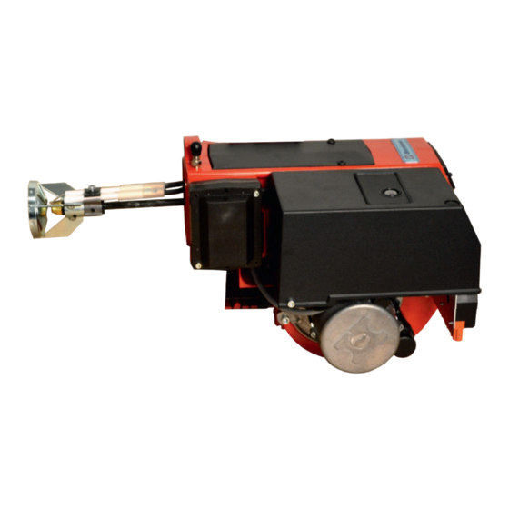
- Page 1 178 131 52-3 P93783 2022-11-01 Providing sustainable energy solutions worldwide Installation- and maintenance instruction B 30 A2.2H LMO24.255C2E A2L 65 CK Translation of the original instructions.
- Page 2 1~230V 1,0A 50Hz IP 20 Motor supply MADE IN SWEDEN BY 1. Manualer på övriga språk 1. Manuals in other languages 1. Manualer på andre sprog 2. www.bentone.com\ 2. www.bentone.com\download 2. www.bentone.com\ nedladdning eller scanna or scan QR-code. download eller scan QR-koden.
-
Page 3: Table Of Contents
Check oil line seals ..............19 Safety ....................4 Example of Basic settings ............20 Air setting ..................21 Technical data ...............6 Dimensions B 30 A2.2H ............... 6 Pump ..................22 Burner installation ................ 7 SUNTEC A2L 65CK/75CK ............22 2.3 Working field .................. -
Page 4: General Information
Make sure that the burner is suitable for the application (see Technical • Data). All components must be installed without being bent, twisted or • subjected to mechanical or thermal forces that affect components. 165 105 01-2 2021-12-07 Bentone... - Page 5 When in operation, the burner’s noise level can exceed 85 dBA – use • hearing protection! - Operation: Carry out all stipulated settings, service and inspection work within • the set time. • If the oil burner control has a solid red light, contact your installer. Bentone...
-
Page 6: Technical Data
• HVO/XTL according to EN 15940. • Fuel oil according to DIN 51603-1. • Fuel oil A Bio 10 according to DIN 51603-6. Dimensions B 30 A2.2H Ø B Ø C 174/315 * Min. recommended distance to floor. Dimensions flange 2.1.1... -
Page 7: Burner Installation
4.5-15.0 kg/h 55-175 kW mbar Do not exceed working field. -0,5 Basic settings - Fuel oil Air settings Nozzle assembly Scale <˚ Burner output Scale nozzle assembly and air damper without damper motor. Settings air damper with damper motor. Bentone... -
Page 8: Basic Settings - Hvo/Xtl
(blue flame), the signal lamp in the reset button flashes green. By lowering the air velocity or changing the flame detector to QRC1 A1, the flame signal can be improved. Technical specification B 30 A2.2H Main supply 230V, 1~, 2.6/3.1A, 50Hz, IP20 Max fuse rating preheater excluded 1.30A, 281W... -
Page 9: Setting Of Ignition Electrodes And Brake Plate
2.0-3.0 5.0-6.0 Nozzle and pump pressure Due to different furnace geometries and capacities, it is not possible to recommend a nozzle model. Nozzle: 45° Solid/semisolid 60° Solid/semisolid 80° Solid/semisolid Pump pressure: 10 bar (8-25 bar) depending on pump model Bentone... -
Page 10: Nozzle Table
1060 93,70 1111 97,88 1161 101,85 1208 1039 26,00 96,81 1148 101,50 1204 1035 106,04 1258 1081 110,33 1308 1168 /s (cSt) at a density of 830 kg/m The table applies to oil with a viscosity of 4.4 mm Bentone... - Page 11 1057 1267 1089 24,00 1254 1078 1297 1116 1341 1153 1382 1188 26,00 1359 1168 1406 1209 1453 1249 1497 1287 The table applies to oil with a viscosity of 4.4 mm2/s (cSt) at a density of 830 kg/m3. Bentone...
-
Page 12: 2.10 Components
Connecting pipe Stage 1 Ignition electrodes Nozzle assembly Fan wheel Air intake Connecting pipe Stage 2 Ignition cable Motor Solenoid valve Ignition transformer Nozzle assembly adjustment Reset button Flame tube Air damper Connecting pipe, pump- Electric panel Photo cell adjustment device Bentone... -
Page 13: Electric Equipment
The cables of the safety system must be separated so that the outgoing signal is not placed in the same cable as the incoming signal. Wiring diagram Brown Blue Green Yellow Gn/Ye Green/Yellow Black Grey White Orange Violet 165 105 16-2 Bentone... -
Page 14: Function Lmo14/24
< 1 s < 1 s -5 - +60°C -20 - +60°C Ambient temperature Min detector current required (with fl ame) 45 µA dc 45 µA dc Max perm. detector current (without fl ame) 5.5 µA dc 5.5 µA dc Bentone... -
Page 15: Colour Codes Lmo14/24
If the reset button is instead kept pressed a second time for at least 3 seconds, you can, via an interface, obtain the corresponding information on a computer or flue gas analyser. To return to normal operation: Press the reset button for 1 second. Bentone... -
Page 16: Installation
Transport damage must be reported to the shipping company. Preparing for installation Check that the burner’s dimensions and capacity range are suitable for the relevant boiler. The power data on the rating plate refers to the burner’s minimum and maximum power. 165 205 19-2 Bentone... -
Page 17: Oil Distribution
Electrical connection must be done in accordance with the applicable • regulations. Burners must be connected to an all-pole switch. • • Connection must conform to the wiring diagram. Use appropriately sized fuses. • If any electrical connection is used other than that recommended by Enertech, there may be a risk of damage to property and personal injury. Bentone... -
Page 18: Handling And Lifting Instruction
Handling and lifting instruction The lifting aid are available as spare parts. 165 105 03-2 Bentone... -
Page 19: Mounting Of Burner On Boiler
Connect the burner electrically, (see chapter Service). Check oil line seals When the burner has been installed and put into operation, the tightness of the various coupling elements should be checked, in case of leakage - retighten the coupling elements. 165 105 04-2 Bentone... -
Page 20: Example Of Basic Settings
Once the burner has started and established flame, it is necessary to adjust the settings so that they are adapted to the installation and the fuel used. B 30 A2.2H Burner output: 156 kW Estimated nozzle output: 156 / 11.86*... -
Page 21: Air Setting
Use a hex key to screw the socket (B) in to decrease or out to increase. The damper position can be read on the damper scale (C). Start burner and check/adjust combustion. Recommended excess air Excess air fl ue gases Max. % CO % CO Lambda 1.2 ≈12.5 3–5 15.4 165 105 18-2 Bentone... -
Page 22: Pump
Nozzle outlet G 1/8” Stage 2 and Stage 1 Pressure gauge port G 1/8” Vacuum gauge port G 1/8” Pressure adjustment Solenoid valve 1 Solenoid valve 2 165 105 10-2 2022-10-31 Bentone... -
Page 23: Pump Operating Principle
Shaft seal By-pass Back to suction plug Gear set Oil under suction By-pass plug Oil under pressure Vacuum gauge port removed By-passed oil returned to tank, or to suction Return plugged Suction Return One pipe installation Two pipe installation Bentone... -
Page 24: Suction Line Tables
139 150 108 150 150 150 150 (D-H) max. = 4,5 m **Q = pump capacity @ 0 bar / Pumpenleistung bei 0 bar capacité de l'engrenage à 0 bar/portata della pompa a 0 bar. Two pipe lift system Bentone... - Page 25 5 min. (a condition is that the pump is being lubricated during operation). The tables state the total suction line length in metres at a nozzle capacity of 9,5 Gph. Max. permissible pressure at the suction and pressure side is 2,0 bar. Bentone...
-
Page 26: Replacement Of Pump Filter
Loosen the pump cover’s screws. Remove the fi lter and gasket Mount new gasket and fi lter Refi t the cover Switch on the main power and open the fuel supply. Start burner and check/adjust combustion. When servicing/replacing components that aff ect combustion, fl ue gas analysis and soot test must be carried out following installation. Bentone... -
Page 27: Replacing The Solenoid Valve (Pump)
G 1/4 steel plug G 1/4 plastic plug Filter Cover gasket Cover gaskets + fi lter 10. ”Cover + cover gasket + fi lter” kit 11. Pressure gauge port or vacuum gauge port screw, O-ring 13. Coil 14. Tube assy Bentone... -
Page 28: Service
Ignition system with fl ame guard 10 years 250,000 cycles UV fl ame sensor 10,000 h 500,000 cycles Damper motor 10 years 500,000 cycles Contactor The burner and its components must be recycled according to applicable regulations. 165 405 07-2 2022-10-04 Bentone... -
Page 29: Combustion Device
Do not clean. Refi t fan housing and fi xing fl ange, lock with nut (G). Switch on the main power and open the fuel supply. Start burner and check/adjust combustion. When servicing/replacing components that aff ect combustion, fl ue gas analysis and soot test must be carried out following installation. 165 405 13 Bentone... -
Page 30: Air Damper
Clean the air damper and air intake (I), lubricate the damper shaft if necessary. Refi t air damper and regulator. Refi t the intake grille. Switch on the main power and open the fuel supply. Start burner and check/adjust combustion. When servicing/replacing components that aff ect combustion, fl ue gas analysis and soot test must be carried out following installation. 165 405 15 Bentone... -
Page 31: Fan
Replace drive shaft coupling on pump. Refi t coupling, pump and motor, making sure drive shaft is connected correctly at both ends. Switch on the main power and open the fuel supply. When servicing/replacing components that aff ect combustion, fl ue gas analysis and soot test must be carried out following installation. 165 405 17 Bentone... -
Page 32: Replace Oil Pump
Switch on the main power and open the fuel supply. Bleed the pump, start the burner and set the correct oil pressure (see Technical data for correct output). Start burner and check/adjust combustion. When servicing/replacing components that affect combustion, flue gas analysis and soot test must be carried out following installation. 165 405 19 Bentone... -
Page 33: Replacement Of Electrical Components
Note the connection of the existing component and disassemble. Fit new component with same connection or with specified alternative connection. Switch on the main power and check the operation of the new component. Start burner and check/adjust combustion. When servicing/replacing components that affect combustion, flue gas analysis and soot test must be carried out following installation. 165 105 11-3 Bentone... -
Page 34: Vibrations
• Check tightness of fasteners. Check fan wheel for damage and contamination (replace if necessary). • Check motor shaft and bearings. If they are worn, replace the motor. • Use screw to attach the vibration sensor. 165 405 22 Bentone... -
Page 35: Fault Location
Preheater temperature too low Check preheater function New oil type Adjust the preheater‘s set operating temperature Check that the oil used has the physical parameters that the burner is rated for. If not, change the oil. 165 105 09-2 2021-01-21 Bentone... -
Page 36: Delayed Ignition
Check that the oil used has the physical parameters that the burner is rated for. If not, change the oil. Temperature of the oil from the tank is too low, increase the temperature of oil from tank Clean the pump filter Bentone... -
Page 37: Pump Pressure
Change the oil or the pump‘s oil parameters Pump worn Replace the pump Pump run using impure oil that has worn the Replace pump and install self-cleaning pump out prematurely filter in the oil system Blocked pump filter Check, clean pump filter Bentone... -
Page 38: Log Of Flue Gas Analysis
Log of flue gas analysis Tel. no: Owner Adresss Tel. no: Installation Boiler Type Make Power kW Burner Type Model Serial no. Fuel Step 1 Step 2 Step 3 Draught in fireplace Fan Press mbar Filter smoke number Flue gas temp. °C Setting brake disc Setting Air damper Pump pressure... - Page 39 EU Declaration of conformity Bentone Oil Burners Type: BF 1 ST 133 B 40 B 65 ST 108 ST 146 B 45 B 70 ST 120 B 30 B 55 B 80 This declaration of conformity is issued under the sole responsibility of the manufacturer.
- Page 40 UK Declaration of conformity Bentone Oil Burners Type: BF 1 ST 133 B 40 B 65 ST 108 ST 146 B 45 B 70 ST 120 B 30 B 55 B 80 This declaration of conformity is issued under the sole responsibility of the manufacturer.
Need help?
Do you have a question about the B 30 A2.2H and is the answer not in the manual?
Questions and answers