
Subscribe to Our Youtube Channel
Related Manuals for Bentone B30A2.2H


Summary of Contents for Bentone B30A2.2H
- Page 1 178 066 52-1 2016-04-18 Providing sustainable energy solutions worldwide Installation- and maintenance instruction B30A2.2H B30A2.2HL...
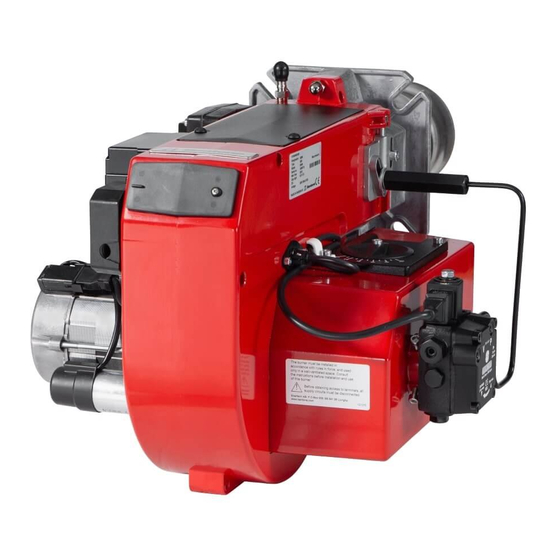
- Page 3 DESCRIPTION Components 1. Brake plate 10. Switch I-II 19. Connecting pipe Stage 1 2. Nozzle 11. Switch I-0 20. Air intake 3. Ignition electrodes 12. Fan wheel 21. Connecting pipe Stage 2 4. Nozzle assembly 13. Motor 22. Solenoid valve 5.
-
Page 4: Technical Data
TECHNICAL DATA Type designation B30A2 Dimensions ø108 160-190 Burner tube Length of burner tube Measure B Standard Long design Output range and nozzles recommended Burner tube Oil capacity Output Recommended nozzle Recommended pump pressure kg/h Mcal/h Angle Danfoss Monarch 4,5-15,0 53-178 46-153 45°... -
Page 5: General Instructions
GENERAL INSTRUCTIONS General rules Condensation in chimney Oil supply The installation of an oil burner should A modern burner works with less ex- The oil line should be dimensioned be carried out in accordance with local cess air and often also with smaller in accordance with the pump regulations. - Page 6 GENERAL INSTRUCTIONS General rules Condensation in chimney Oil supply The installation of an oil burner should A modern burner works with less ex- The oil line should be dimensioned be carried out in accordance with local cess air and often also with smaller in accordance with the pump regulations.
-
Page 7: Air Adjustment
GENERAL INSTRUCTIONS Adjustment of nozzle assembly Adjust the nozzle assembly with the adjustment screw D to the desired position. Air adjustment First stage: Set the operating switch (S2) on low capacity (I). Loosen the screw (A) and turn the damper to the position wan-ted. - Page 8 MAINTENANCE Warning: Before doing any service switch off power at the main switch and cut off the oil supply. Service of burner head Open the cover and disconnect the connecting pipes by loosening screw A and nut B. 1. Loosen or swing out the burner from the boiler.
-
Page 9: Electric Equipment
ELECTRIC EQUIPMENT Oil burner control: LMO24.255 Wiring diagram If the boiler is not equipped with wired contacts,connect the enclosed contacts to terminals X4 and X6 in accordance with wiring diagram. 1N ~ 50/60 Hz 230 V 1(3) 171 435 26 09-01... - Page 10 ELECTRIC EQUIPMENT List of components Oil burner control: LMO24.255 A1 Oil burner control S6 Control thermostat, high/low B1 Photoresistor capacity Fuse S7 Main switch H1 Lamp, low capacity Ignition transformer H3 Lamp, lock-out signal 230 V X1 Connection terminal board K1 Thermal overload protection X2 Earth terminal M1 Burner motor...
- Page 11 ELECTRIC EQUIPMENT Colour codes LMO14/24 When the burner starts, three signal lights in the reset switch indicate the normal sequence, as well as provide indication if something ab- normal is happening in accordance with the following table: Preheater in operation Solid yellow Ignition switched on Flashing yellow...
- Page 12 INSTRUCTIONS PUMP TYPE SUNTEC A2L 65C - 75C Technical data One or two-pipe system. Viscosity range: 2-12 mm Pressure range: 8-15 bar Rated voltage of coil: 220/240V 50/60 Hz Oil temperature: max 60°C Components 1. Nozzle outlet G 1/8" Stage 2 2.
- Page 13 INSTRUCTIONS PUMP TYPE SUNTEC A2L 65C - 75C Pump operating principle for Solenoid valve 2 (NC) closed Solenoid valve 1 (NC) closed A2L 65C - 75C Solenoid valve 2 Solenoid valve 1 (NC) open (NC) open The SUNTEC A2L oil pump has two nozzle outlets.
-
Page 14: Nozzle Table
NOZZLE TABLE Pump pressure bar kg/h Mcal/h kg/h Mcal/h kg/h Mcal/h kg/h Mcal/h 0,40 1,33 1,41 1,49 1,56 0,50 1,66 1,76 1,86 1,95 0,60 2,00 2,12 2,23 2,34 0,65 2,16 2,29 2,42 2,54 0,75 2,49 2,65 2,79 2,93 0,85 2,83 3,00 3,16 3,32... - Page 15 NOZZLE TABLE Pump pressure bar kg/h Mcal/h kg/h Mcal/h kg/h Mcal/h kg/h Mcal/h 0,40 1,63 1,70 1,76 1,82 0,50 2,04 2,12 2,20 2,28 0,60 2,45 2,55 2,64 2,73 0,65 2,65 2,75 2,86 2,96 0,75 3,08 3,18 3,30 3,42 0,85 3,47 3,61 3,74 3,87...
-
Page 16: Fault Location
FAULT LOCATION Burner fails to start Situation Possible causes Remedies Motor runs Flame instability Burner pre-purges Check nozzle to burner head dimension Incorrect head settings and electrode position Low oil pressure Check oil pressure Flame occurs Excess air Adjust air damper Burner locks out Check that photocell is clean and unobstructed... - Page 17 In that the burner conforms to the above mentioned standards it is awarded the CE mark. Indem der Brenner die obengenannten Normen und Richtlinien erfüllt, erhält der Brenner die CE-Kennzeichnung. Du fait de leur conformité aux directives mentionnées ci-dessus, les brûleurs Bentone bénéfi cient du marquage CE. Ljungby, Sweden, 150227 (27/02/15) Enertech AB, Bentone Division/ är kvalitetscertifi...
-
Page 18: Starting Precautions
OIL BURNERS MAINTENANCE INSTRUCTIONS General information If the burner starts but does not ignite Make an attempt to start the burner. Keep the boiler room clean. Ensure that the boiler room has permanent fresh air intake. Switch off before Never make close repeated start attempts. dismantling the oil burner. - Page 20 Enertech AB. P.O Box 309, SE-341 26 Ljungby. www.bentone.se, www.bentone.com...
Need help?
Do you have a question about the B30A2.2H and is the answer not in the manual?
Questions and answers