
Subscribe to Our Youtube Channel
Related Manuals for Bentone B 55-2H


Summary of Contents for Bentone B 55-2H
- Page 1 178 134 66-1 P93783 2023-02-07 Providing sustainable energy solutions worldwide Installation- and maintenance instruction B 55-2H LMO24.255C2E RSA 95 60Hz Translation of the original instructions.
- Page 2 1~230V 1,0A 50Hz IP 20 Motor supply MADE IN SWEDEN BY 1. Manualer på övriga språk 1. Manuals in other languages 1. Manualer på andre sprog 2. www.bentone.com\ 2. www.bentone.com\download 2. www.bentone.com\ nedladdning eller scanna or scan QR-code. download eller scan QR-koden.
-
Page 3: Table Of Contents
Delivery inspection................ 4 Safety ....................4 Components ................. 21 6.3 Mounting/dismounting by-pass plug ........21 Technical data ...............6 Purging ..................21 Dimensions B 55-2H ..............6 6.5 Replacing the filter ..............21 Burner installation ................ 6 Function ..................22 2.3 Working field .................. 7 Suction line tables ............... 23 2.4... -
Page 4: General Information
Make sure that the burner is suitable for the application (see Technical • Data). All components must be installed without being bent, twisted or • subjected to mechanical or thermal forces that affect components. 165 105 01-2 2021-12-07 Bentone... - Page 5 When in operation, the burner’s noise level can exceed 85 dBA – use • hearing protection! - Operation: Carry out all stipulated settings, service and inspection work within • the set time. • If the oil burner control has a solid red light, contact your installer. Bentone...
-
Page 6: Technical Data
When operating with a hot air boiler, the LMO24.255 or LMO44.255 control unit must be used. Fuels: Fuel oil according to DIN 51603-1. • Fuel oil A Bio 10 according to DIN 51603-6. • Dimensions B 55-2H øB øC Ø B Ø C 274/374/474 * Min. -
Page 7: Working Field
Working field 13.0-67.5 kg/h 155-800 kW mbar Do not exceed working field. -1,0 Setting for nozzle assembly and air damper Air settings Nozzle assembly Scale Burner output Bentone... -
Page 8: Setting Of Ignition Electrodes And Brake Plate
Technical specification B 55-2H Main supply, Operating 230V, 1~, 1.2A, 60Hz, IP20 Main supply, Motor 230/400V, 5.8/3.3A 6.3A Max fuse rating -class 90dBA Noise level Motor excluded. Measurements according to EN 15036-1:2006 Alt.1 The noise level of the burner can be reduced by equipping the burner with silencer. -
Page 9: Nozzle Table
1267 1089 24,00 1254 1078 1297 1116 1341 1153 1382 1188 26,00 1359 1168 1406 1209 1453 1249 1497 1287 The table applies to oil with a viscosity of 4.4 mm /s (cSt) at a density of 830 kg/m Bentone... - Page 10 54,94 56,45 57,92 59,36 12,00 59,93 61,58 63,19 64,76 14,00 69,92 71,84 73,72 75,55 16,00 79,91 82,11 84,25 86,34 1024 The table applies to oil with a viscosity of 4.4 mm /s (cSt) at a density of 830 kg/m Bentone...
-
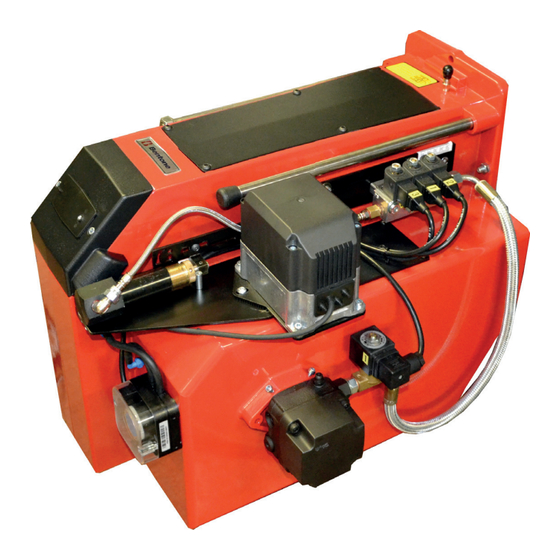
Page 11: Components
Reset button Fixing flange Regulator, air damper Switch I-II Indicator lamp Stage 2 Ignition transformer Flame tube Flame detector Fan wheel Air intake Control box Electrical connection Safety valve Contactor/Thermal Pump Motor overload protection Solenoid valve Stage 1 Air damper Bentone... -
Page 12: Electric Equipment
The cables of the safety system must be separated so that the outgoing signal is not placed in the same cable as the incoming signal. Wiring diagram Brown Blue Green Yellow Gn/Ye Green/Yellow Black Grey White Orange Violet 165 405 54 Bentone... -
Page 13: Function
< 1 s < 1 s Ambient temperature -5 - +60°C -20 - +60°C Min detector current required (with fl ame) 45 µA dc 45 µA dc Max perm. detector current (without fl ame) 5.5 µA dc 5.5 µA dc Bentone... -
Page 14: Colour Codes
If the reset button is instead kept pressed a second time for at least 3 seconds, you can, via an interface, obtain the corresponding information on a computer or flue gas analyser. To return to normal operation: Press the reset button for 1 second. Bentone... -
Page 15: Installation
Bleed the oil system. The oil pump/oil preheater may be damaged if • run dry. The vacuum in the suction line should not fall below 0.3 bar during start-up. 165 205 19-3 Bentone... -
Page 16: Electrical Connection
Electrical connection must be done in accordance with the applicable • regulations. Burners must be connected to an all-pole switch. • • Connection must conform to the wiring diagram. Use appropriately sized fuses. • If any electrical connection is used other than that recommended by Enertech, there may be a risk of damage to property and personal injury. Bentone... -
Page 17: Handling And Lifting Instruction
Handling and lifting instruction The lifting aid we used here are available as spare parts. 165 205 33-2 Bentone... -
Page 18: Mounting
Check oil line seals When the burner has been installed and put into operation, the tightness of Use Loctite 5188 on the various coupling elements should be checked, in case of leakage - tighten threaded oil lines. the coupling elements. 165 105 51-2 2022-03-31 Bentone... -
Page 19: Example Of Basic Settings
Basic settings should only be seen as setting values to get burner to start. Once the burner has started and established flame, it is necessary to adjust the settings so that they are adapted to the installation and the fuel used. B 55-2H Burner output: 627 kW Estimated nozzle output: 627 / 11.86*... -
Page 20: Brake Plate Adjustment
This should then be used when making settings in the burner control system. Check air settings with flue gas analysis. Recommended excess air Excess air flue gases Max. % CO % CO Lambda 1.2 3–5 ≈12.5 15.4 165 405 60 Bentone... -
Page 21: Pump Rsa 95/125
Replace the oil fiter on the oil pump as follows.. • Close the oil valves. Unscrew the cover (4 x 5 mm Allen screws). • Replace the oil filter. • Replace the cover gasket. • Refit the cover. • Open the oil valves. • 165 105 54 Bentone... -
Page 22: Function
Only for capacities over 100 kg/h or on special request by customer Hydraulic control device Only on burners with hydraulic air control or nozzle assembly optimisation. Oil pump Items 3 and 6 are not fitted to two-stage burners. Item 8 is connected after solenoid valve nozzle 2 (Y2). Bentone... -
Page 23: Suction Line Tables
5 min. (a condition is that the pump is being lubricated during operation). The tables state the total suction line length in metres at a viscosity of 6,0 mm Bentone... -
Page 24: Service
Ignition system with fl ame guard 10 years 250,000 cycles UV fl ame sensor 10,000 h Damper motor 500,000 cycles Contactor 10 years 500,000 cycles The burner and its components must be recycled according to applicable regulations. 165 405 07-2 2022-10-04 Bentone... -
Page 25: Combustion Device
Install flame tube, be sure to install the drainage hole downwards (not available on all flame tubes) so that any oil spills can drain out. Close boiler/hinged flange. Switch on the main power and open the fuel supply. Start burner and check/adjust combustion. When servicing/replacing components that affect combustion, flue gas analysis and soot test must be carried out following installation. 165 205 36-2 Bentone... -
Page 26: Air Damper
Clean the air damper and air intake (I), lubricate the damper shaft if necessary. Refi t air damper and regulator. Refi t the intake grille. Switch on the main power and open the fuel supply. Start burner and check/adjust combustion. When servicing/replacing components that aff ect combustion, fl ue gas analysis and soot test must be carried out following installation. 165 405 43 Bentone... -
Page 27: Fan
Replace drive shaft coupling on pump. Refi t coupling, pump and motor, making sure drive shaft is connected correctly at both ends. Switch on the main power and open the fuel supply. When servicing/replacing components that aff ect combustion, fl ue gas analysis and soot test must be carried out following installation. 165 405 77 Bentone... -
Page 28: Replace Oil Pump
Fit new oil hoses. Switch on the main power and open the fuel supply. Bleed the pump. Start burner and check/adjust combustion. Use caution when operating the burner, surfaces may be hot. When servicing oil bearing components, check the oil density when the burner is commissioned after servicing. When servicing/replacing components that affect combustion, flue gas analysis and soot test must be carried out following installation. 165 405 57 Bentone... -
Page 29: Tightness Check Of Solenoid Valves
Disconnect the power supply to solenoid valves Y1, Y2 and Y3. • Provide power to safety solenoid valve Y1S. • Run motor and pump - check that no oil is coming out of the nozzle, • replace solenoid valve if necessary. Use Loctite 5188 on threaded oil pipelines. When servicing/replacing components that affect combustion, flue gas analysis and soot test must be carried out following installation. 165 405 23 Bentone... -
Page 30: Replacement Of Electrical Components
Note the connection of the existing component and disassemble. Fit new component with same connection or with specified alternative connection. Switch on the main power and check the operation of the new component. Start burner and check/adjust combustion. When servicing/replacing components that affect combustion, flue gas analysis and soot test must be carried out following installation. 165 105 11-3 Bentone... -
Page 31: Vibrations
• Check tightness of fasteners. Check fan wheel for damage and contamination (replace if necessary). • Check motor shaft and bearings. If they are worn, replace the motor. • Use screw to attach the vibration sensor. 165 405 46 Bentone... -
Page 32: Fault Location
Preheater temperature too low Check preheater function New oil type Adjust the preheater‘s set operating temperature Check that the oil used has the physical parameters that the burner is rated for. If not, change the oil. 165 105 09-2 2021-01-21 Bentone... -
Page 33: Delayed Ignition
Check that the oil used has the physical parameters that the burner is rated for. If not, change the oil. Temperature of the oil from the tank is too low, increase the temperature of oil from tank Clean the pump filter Bentone... -
Page 34: Pump Pressure
Change the oil or the pump‘s oil parameters Pump worn Replace the pump Pump run using impure oil that has worn the Replace pump and install self-cleaning pump out prematurely filter in the oil system Blocked pump filter Check, clean pump filter Bentone... -
Page 35: Log Of Flue Gas Analysis
Log of flue gas analysis Tel. no: Owner Adresss Tel. no: Installation Boiler Type Make Power kW Burner Type Model Serial no. Fuel Step 1 Step 2 Step 3 Draught in fireplace Fan Press mbar Filter smoke number Flue gas temp. °C Setting brake disc Setting Air damper Pump pressure... - Page 36 EU Declaration of conformity Bentone Oil Burners Type: BF 1 ST 133 B 40 B 65 ST 108 ST 146 B 45 B 70 ST 120 B 30 B 55 B 80 This declaration of conformity is issued under the sole responsibility of the manufacturer.
- Page 37 UK Declaration of conformity Bentone Oil Burners Type: BF 1 ST 133 B 40 B 65 ST 108 ST 146 B 45 B 70 ST 120 B 30 B 55 B 80 This declaration of conformity is issued under the sole responsibility of the manufacturer.
- Page 40 Enertech AB. P.O Box 309, SE-341 26 Ljungby www.bentone.com...
Need help?
Do you have a question about the B 55-2H and is the answer not in the manual?
Questions and answers