
Related Manuals for Bentone B 30 A2.2


Summary of Contents for Bentone B 30 A2.2
- Page 1 178 095 52-1 2019-10-10 Providing sustainable energy solutions worldwide Installation- and maintenance instruction B 30 A2.2 Original translation of Installation- and maintenance instruction...
- Page 2 Beispiel Manualer på övriga språk www.bentone.com\nedladdning Serial no. 352011030141 1234567 Man.Year 2019 Designation BF 1 KS 76-24 eller scanna QR-koden BF 1 Type BF 1 KS 76-24 Model LIGHT OIL 35-90kW 1,25-6,0 cSt 7-14bar Cap. Min-Max Skriv in brännarens artikelnummer som finns på din...
-
Page 3: Table Of Contents
10.2 Burner will not start after normal use ________________ 36 10.3 Delayed ignition __________________________________ 37 10.4 Noise in pump ___________________________________ 37 10.5 Pump pressure __________________________________ 37 11. Log of flue gas analysis ____________________________ 39 12. Oil burners maintenance instructions _______________ 40 Bentone... -
Page 4: General Information
• Burner pipes, fan wheels and air dampers may contain sharp edges. • The surface temperature of the burner’s components can exceed 60 °C. • Caution: The burner has moving parts, and there is risk of crushing injuries. 165 105 01 Bentone... - Page 5 - flue gas ducts and combustion air ducts are not blocked - all actuators and control and safety devices are in working order and correctly set • After commissioning, if a steady red light on the burner control is displayed, contact your installation technician. Bentone...
- Page 6 Delivery check • Make sure everything is delivered and the goods have not been damaged during transit. • If something is wrong with a delivery, report it to the supplier. • Transport damage must be reported to the shipping company. Bentone...
-
Page 7: Technical Data
• Light oil, B10 heating oil/biofuel blend (as defined in DIN V51603-6) and is used for: • Water heating generators • Hot air generators (these require LMO 24 255 C2E) 2.1 Dimensions B 30 * Min. recommended distance to floor. Ø B Ø C B 30 187/315 165 105 02 Bentone... -
Page 8: Working Field B 30A2
100 110 120 130 140 150 160 170 180 2.2.1 Electric Specification Burner correspond to IP 20 Type Motor Complete Sound burner 180W 1,3A 230V 230V 2,63A 84 dBA ± 0,5 B 30 50Hz 5µF 50Hz Max operating current, see data plate Bentone... -
Page 9: Setting Of Brake Plate And Air Flow
80° Solid/semisolid Pump pressure 10 bar (8-25 bar) depending on pump model 2.5 Burner installation 2.5.1 Hole patten Make sure the hole pattern on the boiler is designed for burner flange. Combustion device B 30 ø 115-150 M8-M12 ø 160-190 Bentone... -
Page 10: Nozzle Table
89,36 1060 93,70 1111 97,88 1161 101,85 1208 1039 26,00 96,81 1148 101,50 1204 1035 106,04 1258 1081 110,33 1308 1168 The table applies to oil with a viscosity of 4.4 mm /s at a density of 830 kg/m Bentone... - Page 11 1057 1267 1089 24,00 1254 1078 1297 1116 1341 1153 1382 1188 26,00 1359 1168 1406 1209 1453 1249 1497 1287 The table applies to oil with a viscosity of 4.4 mm /s at a density of 830 kg/m Bentone...
-
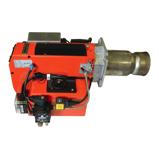
Page 12: Description B 30
19. Air intake Nozzle assembly 12. Fan wheel 20. Connecting pipe Stage 1 Ignition cable 13. Motor 21. Solenoid valve 22. Connecting pipe Stage 2 Ignition transformer 14. Nozzle assembly adjustment Reset button 15. Blast tube Electric panel 16. Damper motor Bentone... -
Page 13: General Instructions
The system must be fine-tuned at start-up. The temperature in the chimney must be at least 60 °C at 0.5 m down in the chimney to prevent condensation. 165 105 03 Bentone... -
Page 14: Installation
4. Installation 4.1 Handling and lifting instruktion The lifting aid are available as spare parts, Bentone... -
Page 15: Acceptance Inspection
• The connection should be made in accordance with the wiring diagram. • Fuse rating is as required If any electrical connection is used other than that recommended by Bentone, there may be a danger of damage to property and personal injury. -
Page 16: Mount The Burner On The Boiler
Once the burner has been installed and commissioned, the seals of the various coupling elements should be checked (A). When a leak is detected, it is usually sufficient to tighten the coupling element that is leaking. The picture shows burner B 30A 2,2H 165 105 04 Bentone... -
Page 17: Air Adjustment With Damper Motor
Reset the control switch to High Load and make sure the correct air quantity exchange of damper motor. is reached. Solenoid valve High capacity (black) High capacity (red) Low capacity (orange) Closed damper (blue) Releasing button N.B. The upper position is the standard position 165 105 05 Bentone... -
Page 18: Burner Installation
These are the default settings and controlling the combustion will take place during operation. Selection of power and connection between the different power stages must be selected and adjusted so that the system achieves good functionality 165 105 06 Bentone... -
Page 19: Setting Values For Nozzle Assembly B 30
See under Basic settings Note that it is simply a matter of a basic setting that should be adjusted retrospectively once the burner has started. A flue gas analysis and soot quantity measurement must be carried out when fine-tuning the burner. Bentone... -
Page 20: Burner Servicing
Close the boiler / spectacle flange. nozzles. Do not Turn on the main power. clean. Check combustion*. Note: When servicing/replacing components that affect combustion, an analysis and soot test shall be carried out on the installation. 165 105 07 Bentone... -
Page 21: Servicing Air Dampers
Make sure the damper axle is properly mounted. Install the intake grille for the air intake. Release the damper motor release button. Check/adjust the combustion. Note: When servicing/replacing components that affect combustion, an analysis and soot test shall be carried out on the installation. Bentone... -
Page 22: Replacement Of Damper Motor
Install the new damper motor on the mounting plate. Connect the damper motor’s cables. Re-install the damper motor and mounting plate on the air intake according to the instructions on servicing the air damper. Turn on the mains power. Check/adjust the combustion. Bentone... -
Page 23: Servicing The Fan
Disconnect the motor’s electrical cable Remove the motor Remove the drive shaft and drive coupling from the motor Disconnect the drive coupling from the pump Fit the coupling, pump, and motor. Make sure the drive shaft is connected correctly at both ends Bentone... -
Page 24: Replacement Of Oil Pump
Bleed the pump, start the burner and set the correct oil pressure (refer to technical data for correct output). Check combustion.* Note: When servicing/replacing components that affect combustion, an analysis and soot test shall be carried out on the installation. Bentone... -
Page 25: Vibration
Maximum vibration level are 5,0 mm/s • Check all bolts and nuts for correct torque • Check fan wheel for damage and contamination. Change when dirty/ unbalanced • Check motor bearings. If worn change motor/bearings Use lid screw hole for sensor mounting Bentone... -
Page 26: Instructions Pump
Nozzle outlet G 1/8” Stage 2 and stage 1 Pressure gauge port G 1/8” Vacuum gauge port G 1/8” Pressure adjustment Solenoid valve 1 Solenoid valve 2 165 105 10 Bentone... - Page 27 Bleed Bleeding in two-pipe operation is automatic : it is assured by a bleed flat on the piston. In one-pipe operation, the plug of a pressure gauge port must be loosened until the air is evacuated from the system Bentone...
- Page 28 (D-H) max. = 4,5 m 150 150 139 150 108 150 150 150 150 **Q = pump capacity @ 0 bar / Pumpenleistung bei 0 bar Two pipe lift system capacité de l'engrenage à 0 bar/portata della pompa a 0 bar. Bentone...
- Page 29 5 min. (a condition is that the pump is being lubricated during operation). The tables state the total suction line length in metres at a nozzle capacity of 9,5 Gph. Max. permissible pressure at the suction and pressure side is 2,0 bar. Bentone...
- Page 30 Mount new gasket and filter Refit the cover Open the oil supply Start the burner and check seals and combustion Note: When servicing/replacing components that affect combustion, an analysis and soot test shall be carried out on the installation. Bentone...
- Page 31 G 1/4 gasket G 1/4 steel plug G 1/4 plastic plug Filter Cover gasket Cover gaskets + filter 10. ”Cover + cover gasket + filter” kit 11. Pressure gauge port or vacuum gauge port screw, O-ring 13. Coil 14. Tube assy Bentone...
-
Page 32: Replacement Of Electrical Components
Turn on the mains power. Check the function of the new component. Start the burner. Check combustion.* Note: When servicing/replacing components that affect combustion, an analysis and soot test shall be carried out on the installation. 165 105 11 Bentone... -
Page 33: Wiring Diagram
If the boiler is not equipped with wired contacts,connect the enclosed contacts to terminals X4 and X6 in accordance with wiring diagram. -
Page 34: Oil Burner Control
Reaction time on flame failure: < 1 s < 1 s Ambient temperature: -5 +60°C -20 - +60°C Min. current with flame established: 45 µA dc 45 µA dc Max. photo current at start: 5,5 µA dc 5,5 µA dc Bentone... -
Page 35: Colour Codes Lmo14/24
If the reset button is instead kept pressed a second time for at least 3 seconds, you can, via an interface, obtain the corresponding information on a computer or flue gas analyser. To return to normal operation: Press the reset button for 1 second Bentone... -
Page 36: Fault Location
Check preheater function Preheater temperature too low Adjust the preheater‘s set operating tem- New oil type perature Check that the oil used has the physical parameters that the burner is rated for. If not, change the oil. 165 105 09 Bentone... -
Page 37: Delayed Ignition
Change the oil or the pump's oil parameters Pump worn Replace the pump Pump run using impure oil that has worn the Replace pump and install self-cleaning pump out prematurely filter in the oil system Blocked pump filter Check, clean pump filter Bentone... - Page 38 171 905 28...
-
Page 39: Log Of Flue Gas Analysis
11. Log of flue gas analysis Owner Adresss Tel. no: Installation Tel. no: Boiler Type Make Power Bentone Burner Type Model Serial no. Fuel Step 1 Step 2 Step 3 Draught in fireplace Fan Press mbar Filter smoke number Flue gas temp. °C... -
Page 40: Oil Burners Maintenance Instructions
12. Oil burners maintenance instructions General information If the burner starts but does not ignite Keep the boiler room clean. Ensure that the boiler Make an attempt to start the burner. room has permanent fresh air intake. Switch off before Never make close repeated start attempts. - Page 44 Enertech AB. P.O Box 309, SE-341 26 Ljungby. www.bentone.se, www.bentone.com...
Need help?
Do you have a question about the B 30 A2.2 and is the answer not in the manual?
Questions and answers