SPX PE8 Series Operating Instructions Manual
Hydraulic pump
Hide thumbs
Also See for PE8 Series:
- User manual (24 pages) ,
- Operating instructions manual (17 pages)
Table of Contents
Advertisement
Quick Links
SPX Bolting Systems
Unit 4, Wansbeck Business Park
Rotary Parkway
Ashington
Northumberland NE63 8QW
spxboltingsystems.com
Original Instructions
© SPX
Tel: +44 (0) 1670 850580
Fax: +44 (0) 1670 850655
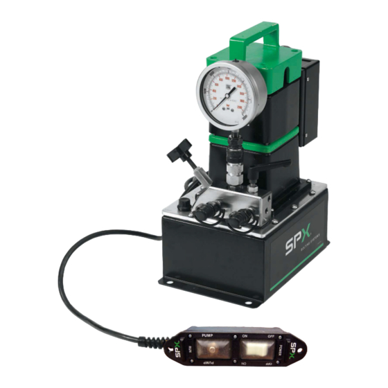
Electric-Powered
PE8 Series
Hydraulic Pump
Operating Instructions for:
PE8LXX3L
PE8PXX3L
Form No. 1000591
Rev. 0 February 8, 2012
Advertisement
Table of Contents

Related Manuals for SPX PE8 Series


Summary of Contents for SPX PE8 Series
- Page 1 Operating Instructions for: PE8LXX3L PE8PXX3L SPX Bolting Systems Tel: +44 (0) 1670 850580 Unit 4, Wansbeck Business Park Fax: +44 (0) 1670 850655 Rotary Parkway Ashington Northumberland NE63 8QW spxboltingsystems.com Original Instructions Electric-Powered PE8 Series Hydraulic Pump Form No. 1000591 Rev.
- Page 2 Form No. 1000591 Rev. 0 February 8, 2012 © SPX...
-
Page 3: Table Of Contents
PE8 Series Electric/Hydraulic Pumps ........ -
Page 4: Description
Description The PE8 series hydraulic pumps are designed to have a maximum of 1500 bar (21,750 psi) at a flow rate of 131 cc/min (8 cu. in/min). All pumps come fully assembled, less fluid, and ready for work. PE8 Series Electric/Hydraulic Pumps... -
Page 5: Safety Symbols And Definitions
Only the user can decide the suitability of this product in these conditions or extreme environments. SPX Hydraulic Technologies will supply information necessary to help make these decisions. Consult your nearest SPX Hydraulic Technologies facility, refer to SPX Hydraulic Technologies Facilities in this document. - Page 6 Hoses also must not come in contact with corrosive material such as creosote- impregnated objects and some paints. Consult the manufacturer before painting a hose. Never paint the couplers. Hose deterioration due to corrosive materials may result in personal injury. Form No. 1000591 Rev. 0 February 8, 2012 © SPX...
- Page 7 • To help prevent personal injury, do not allow personnel to go under or work on a load before it is properly cribbed or blocked. All personnel must be clear of the load before lowering. Form No. 1000591 Rev. 0 February 8, 2012 © SPX...
- Page 8 SAE grade 8 or better fasteners when attaching components to cylinders or rams and tighten securely. • Limiting the stroke and pressure on all cylinders will prolong their life. Form No. 1000591 Rev. 0 February 8, 2012 © SPX...
-
Page 9: Initial Setup
The electric motor is wired for nominal 115 or nominal 230 volts, 50/60 Hz. Nominal 230 volt electric motors are shipped without a plug attached. Please obtain and install the applicable plug for your area. Form No. 1000591 Rev. 0 February 8, 2012 © SPX... - Page 10 Length of Electrical Cord at Maximum Hyd. Pressure 0-8 m 8-15 m 15-30 m 30-46 m 0-25 ft 25-50 ft 50-100 ft 100-150 ft 0.75 0.75 Table 2. Minimum Recommended Gauge Table Form No. 1000591 Rev. 0 February 8, 2012 © SPX...
- Page 11 Switch will automatically return to OFF position when switch is released and pump motor will Figure 6. Pump RUN turn off. 6. See Figure 4. Press the STOP (red) switch to remove power from the pendant. Form No. 1000591 Rev. 0 February 8, 2012 © SPX...
- Page 12 To remove the air: 3. See Figure 9. Open the filler cap two full turns. Figure 9. Filler Cap Form No. 1000591 Rev. 0 February 8, 2012 © SPX...
- Page 13 Item Description Stop (Red) Lamp (White) Start (Green) Figure 12. Power Switch 8. See Figure 13. Using the pendant, press the POWER rocker switch to ON. Figure 13. Power ON Form No. 1000591 Rev. 0 February 8, 2012 © SPX...
- Page 14 Figure 15. Release Position 11. See Figure 16. Press the STOP (red) switch to remove power from the pendant. Item Description Stop (Red) Lamp (White) Start (Green) Figure 16. Power Switch Form No. 1000591 Rev. 0 February 8, 2012 © SPX...
-
Page 15: Operating Instructions
WARNING: To help prevent personal injury, check the voltage rating on the motor Figure 19. Connected to Power Source nameplate to be sure the outlet has the appropriate voltage. Form No. 1000591 Rev. 0 February 8, 2012 © SPX... - Page 16 8. See Figure 23. To release the pressure, rotate the system pressure manual release valve to the release (lever away from the motor) position. HOLD RELEASE Figure 23. Release Position Form No. 1000591 Rev. 0 February 8, 2012 © SPX...
- Page 17 1. See Figure 25. Turn the pressure regulating knob a few turns in the counterclockwise direction. This decreases the pressure. + INCR - DECR Figure 25. Pressure Regulating Valve Form No. 1000591 Rev. 0 February 8, 2012 © SPX...
- Page 18 5. See Figure 28. Using the pendant, press the POWER switch to ON. 6. See Figure 29. Press and hold the PUMP RUN switch. Figure 28. Power ON Figure 29. Pump RUN Form No. 1000591 Rev. 0 February 8, 2012 © SPX...
- Page 19 8. Cycle the system several times to verify the pressure is set correctly. NOTE: Pressure is retained until it is released with system pressure manual release lever. Figure 30. Pressure Regulating Valve Form No. 1000591 Rev. 0 February 8, 2012 © SPX...
-
Page 20: Performance Specifications
Pump 1500 bar (21,750 1500 bar (21,750 and 1500 bar Req'd bar (psi) psi) (115V) psi) (230V) (21,750 psi) PE8 Series 14,000 82-86 Table 3. Drive Unit Requirements Max. Pressure Pump Fluid Delivery* (cu. in./min. @) Output bar (psi) 0 bar (0 psi) 17.2 bar... -
Page 21: General Maintenance
• Compatible with the hydraulic fluid used. A system that does not meet these requirements can fail, possibly resulting in serious injury. If you are in doubt about the components of your hydraulic system, contact SPX Hydraulic Technologies Technical Support. - Page 22 9. Remove the filler cap and insert a clean funnel with a filter. Figure 33. Filter Screen 10. Fill the reservoir with hydraulic fluid to 2.6 cm (1 in.) from the cover plate. Form No. 1000591 Rev. 0 February 8, 2012 © SPX...
- Page 23 18. Fill the reservoir. See Filling the Pump Reservoir. 19. See Figure 35. Remove the protective backing and install the new reservoir gasket with the adhesive side down. Figure 35. Reservoir Gasket Form No. 1000591 Rev. 0 February 8, 2012 © SPX...
- Page 24 Figure 37. 80W90 Oil Level 22. See Figure 38. Clean motor gasket surfaces and install new motor gasket. 23. Position the motor assembly back onto the pump assembly. Figure 38. Motor Gasket Form No. 1000591 Rev. 0 February 8, 2012 © SPX...
- Page 25 @ 38°C (237 SUS @ 100°F) or equivalent. If low temperature requirements are needed, use hydraulic fluid 5.1 cSt @ 100°C (451 cSt @ Figure 41. Filler Cap -40°C). Fill to the proper level. Form No. 1000591 Rev. 0 February 8, 2012 © SPX...
- Page 26 Sound Reduction - Electrically Powered Motor The electrically powered hydraulic pump operates in the 82-86 dBA range. If further sound reduction is desired, contact SPX Power Team Hydraulic Technology technical support for products more suitable to your application. Hose Connections CAUTION: Contamination of the hydraulic fluid could cause the valve to malfunction.
-
Page 27: Troubleshooting Guide
Notes: • For a detailed parts list or to locate a SPX Hydraulic Technologies facility, contact your nearest SPX Hydraulic Technologies facility, refer to SPX Hydraulic Technologies Facilities in this document. • Plug the outlet ports of the pump when checking for leakage to determine if the leakage is in the pump, in the cylinder, or in the tool. - Page 28 Seal leaking pipe fittings with pipe sealant. 2. Loose fittings. 2. Tighten fittings. 3. Internal check is leaking. 3. Contact a SPX Hydraulic Technologies Service Center. Form No. 1000591 Rev. 0 February 8, 2012 © SPX...
- Page 29 3. Attached component sticking or 3. Refer to manufacture's binding. information for attached component. 4. Malfunctioning valve. 4. Verify connections. Contact authorized SPX Hydraulic Technologies facility. Form No. 1000591 Rev. 0 February 8, 2012 © SPX...
-
Page 30: Repair Procedures
3. Replace the fuse. On 115V (nominal) replace 15A time delay 250VAC 5x20mm fuse, 230V (nominal) replace 10A time delay 250VAC 5x20mm fuse. 4. To install, reverse the removal procedure. Figure 45. External Fuse Holder Cap Form No. 1000591 Rev. 0 February 8, 2012 © SPX... -
Page 31: Parts List
Parts List Figure 46. Parts List Form No. 1000591 Rev. 0 February 8, 2012 © SPX... - Page 32 Decal, Plas Info CE US Rect 1.06 in. 32714 Gasket, Pump Body 3000618 Assy, Pendant Tensioning System 115V Pumps: 15A TIME DELAY 250VAC 5x20mm Fuse 230V Pumps: 10A TIME DELAY 250VAC 5x20mm Fuse Form No. 1000591 Rev. 0 February 8, 2012 © SPX...
-
Page 33: Spx Bolting Systems Facilities
SPX Bolting Systems Facilities UNITED ST ATES CHINA EUROPE C E R T I F I E D SPX Hydraulic Technologies Albert Thijsstraat 12 No. 1568 Hua Shan Road International Park Center 6471 WX Eygelshoven 5885 11th Street Shanghai 200052, China... -
Page 34: Ec Declaration Of Conformity
Form No. 1000591 Rev. 0 February 8, 2012 © SPX...
Need help?
Do you have a question about the PE8 Series and is the answer not in the manual?
Questions and answers