Table of Contents
Advertisement
Quick Links
© 2 0 1 4 S P X C O R P O R A T I O N
F o rm N o . 1 0 0 0 5 2 5
R e v . 1 A u g u s t 2 9 , 2 0 1 4
1
T e c h S e r v i c e s : + 1 8 0 0 4 7 7 8 3 2 6
F a x : + 1 8 0 0 7 6 5 8 3 2 6
O r d e r E n t r y : + 1 8 0 0 5 4 1 1 4 1 8
F a x : + 1 8 0 0 2 8 8 7 0 3 1
S P X H y d r a u fl i c T e c h n o fl o g i e s
5 8 8 5 1 1 t h S t r e e t
R o c k f o r d , I L 6 1 1 0 9 - 3 6 9 9 U S A
s p x b o fl t i n g s y s t em s . c om
P E 4 5 I N F I N I T Y T O R Q U E W R E N C H S E R I E S
O p e r a t i n g i n s t r u c t i o n - P a r t s L i s t f o r :
P E 4 5 P E E 4M P R S
P E 4 5 P E E 4 P R S
P E 4 5 Y E E 4 CM P R S
P E 4 5 Y E E 4 C P R S
P E 4 5 Y E E 4M P R S
P E 4 5 Y S S 4 P R S
P E 4 5 L E E 4 CM P R S
P E 4 5 L E E 4 C P R S
P E 4 5 L E E 4M P R S
P E 4 5 L E E 4 P R S
P E 4 5 P E E 4 CM P R S
P E 4 5 P E E 4 C P R S
Advertisement
Table of Contents

Related Manuals for SPX Infinity PE45 Series


Summary of Contents for SPX Infinity PE45 Series
- Page 2 Form No. 1000525 © 2014 SPX CORPORATION Re v . 1 Au g u s t 29 , 2014...
-
Page 3: Table Of Contents
Fuse Replacement Motor Brush Replacement Electrical Cover and Switch Removal and Installation Motor Housing Removal and Installation Cord, Electrical Supply Electrical Bracket Assembly Roll Cage Removal and Installation Universal Motor Removal and Installation Motor Mount Removal and Installation ISP Air Motor Adapter Removal and Installation Motor Shaft Square Key Removal and Installation Pressure Limiting Valve Removal and Installation Solenoid Coil Removal and Installation 2-Way Cartridge Valve Removal and Installation 2-Position/4-Way Valve Removal and Installation Valve Manifold Removal and Installation Reservoir Gasket Replacement Thermometer Replacement Inlet Suction Filter Replacement Return Hose Removal and Installation High Pressure Tube Removal and Installation Form No. 1000525 © 2014 SPX CORPORATION Re v . 1 Au g u s t 29 , 2014... - Page 4 TABLE OF CONTENTS Valve Mounting Block and Gasket Removal and Installation Inlet Suction Fitting Removal and Installation Connector Valve Removal and Installation Pump Fitting Removal and Installation Cartridge Pump Assembly Removal and Installation Reservoir Cover Removal and Installation Parts Lists Schematics Hydraulic Technologies Facilities Declaration of Conformity Form No. 1000525 © 2014 SPX CORPORATION Re v . 1 Au g u s t 29 , 2014...
-
Page 5: Description
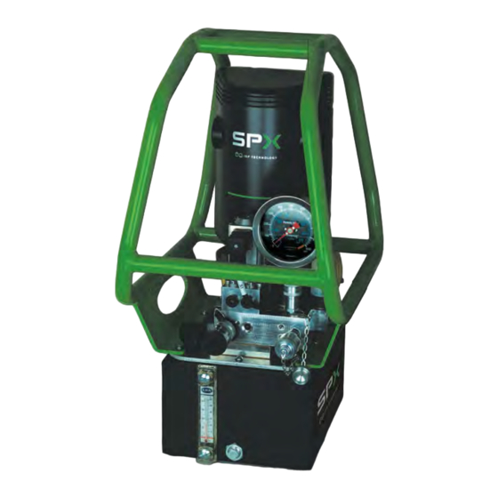
Universal Motor The universal motor pump, shown in Figure 1, offers a lightweight and portable hydraulic pump option. Weight can be up to 40 kg (88 lbs). Universal motor pumps come with a 5.7L (1.5 Gal) capacity hydraulic reservoir. The motor is a 1.3 kW (1.8 HP) average, 115/230 VAC (nominal), 50 / 60 Hz single-phase. Current draw can be up to 17 Amps at 115V and 8.5 Amps at 230V and the sound level is rated at 87-92 dB. Operating temperatures range is -25°C to +50°C (-13°F to 122°F). (If temperatures are at extremes of the operating range, it is recommended to use hydraulic fluids that are rated for those temperatures. It is recommended that you use the cooling fan option for elevated ambient temperature or continuous duty. Figure 1. PE45 Series Pump Form No. 1000525 © 2014 SPX CORPORATION Re v . 1 Au g u s t 29 , 2014... -
Page 7: Safety Symbols And Definitions
• Retract the system before adding fluid to prevent overfilling the pump reservoir. An overfill can cause personal injury due to excess reservoir pressure created when tools are retracted. Form No. 1000525 © 2014 SPX CORPORATION Re v . 1 Au g u s t 29 , 2014... - Page 8 Consult the manufacturer before painting a hose. Never paint the couplers. Hose deterioration due to corrosive materials may result in personal injury. Form No. 1000525 © 2014 SPX CORPORATION Re v . 1 Au g u s t 29 , 2014...
- Page 9 Any loose pieces of tape could travel through the system and obstruct the flow of fluid or cause jamming of precision-fit parts. • Always use protective covers on disconnected quick couplers. Form No. 1000525 © 2014 SPX CORPORATION Re v . 1 Au g u s t 29 , 2014...
-
Page 10: Initial Setup
• Check the voltage at the motor with the pump running at full pressure. Start the pump and shift as required. Turn off the pump when not in use. Form No. 1000525 © 2014 SPX CORPORATION Re v . 1 Au g u s t 29 , 2014... - Page 11 8-15 m 0.75 0.75 Table 2. Minimum Recommended Gauge Table Bleeding Air from the System After all connections are made, the hydraulic system must be bled of any trapped air. With no load on the system and the pump vented and positioned higher than the hydraulic device, cycle the system several times. Check the reservoir fluid level and fill to correct level with Hydraulic Technologies hydraulic fluid as necessary. If there is a problem contact Hydraulic Technologies Technical Support. To locate a Hydraulic Technologies Authorized Hydraulic Service Center, contact your nearest Power Team facility or www.SPXBOLTINGSYSTEMS.com. Form No. 1000525 © 2014 SPX CORPORATION Re v . 1 Au g u s t 29 , 2014...
-
Page 12: Operating Instructions
When the ADVANCE/RETRACT/IDLE is released, the switch defaults to RETRACT. The pump is factory preset to 103 bar (1,500 psi) during RETRACT. Pressing the ADVANCE/RETRACT/IDLE rocker switch to IDLE allows hydraulic fluid to cycle through the pump back to the tank and the motor will shut off. Description Item OFF Position ON Position Idle Position Retract Position Advance Position Figure 3. Pendant Control Form No. 1000525 © 2014 SPX CORPORATION Re v . 1 Au g u s t 29 , 2014... - Page 13 OPERATING INSTRUCTIONS CONTINUED Adjusting The Pressure Regulating Valve The pump must be completely connected. Press the START (green) rocker switch. Using the pendant, press the ON/OFF rocker switch to ON. Press and hold the ADVANCE/RETRACT/IDLE rocker switch to the ADVANCE position to start the motor and build pressure. Rotate pressure regulating valve to the desired pressure. Clockwise increases pressure, counterclockwise decreases pressure. When the desired pressure is achieved, cycle the system again to verify correct pressure setting. Using the pendant press the ON/OFF rocker switch to OFF. Press the OFF (red) switch on the control box. Form No. 1000525 © 2014 SPX CORPORATION Re v . 1 Au g u s t 29 , 2014...
-
Page 15: General Maintenance
WARNING: Contamination of the hydraulic fluid could cause the valve to malfunction. Establish a routine to keep the hydraulic system as free from debris as possible. • Seal unused couplers with protective covers. • Keep hose connections free of debris. • Keep the breather-hole in the filler cap clean and unobstructed. • Use only Power Team hydraulic fluid. Replace hydraulic fluid as recommended, or sooner if the fluid becomes contaminated. Never exceed 300 hours of use between fluid changes. Hydraulic Fluid Level Check the fluid level in the reservoir after each 10 hours of use. The fluid level should be 1.3–3.8 cm (0.5–1.5 in.) from the cover plate or to the FILL LINE when all cylinders are retracted. Drain, flush, and refill the reservoir with an approved Power Team hydraulic fluid after 300 hours of use. The frequency of fluid changes depends upon general working conditions, severity of use, the overall cleanliness and care given to the pump. Fluid should be changed more frequently when the system is not operated regularly indoors. Form No. 1000525 © 2014 SPX CORPORATION Re v . 1 Au g u s t 29 , 2014... - Page 16 Inlet Suction Filters Adding Hydraulic Fluid to the Reservoir Disconnect the power supply. Clean the entire area around the filler cap. See Figure 6. Remove the filler cap, and install a clean funnel with a filter. Use only Power Team hydraulic fluid 47 cSt @ °C (215 SUS @ 100°F). If low temperature requirements are needed, use hydraulic fluid 5.1 cSt @ 100°C (451 cSt @ -40°C). Figure 6. Filler Cap Form No. 1000525 © 2014 SPX CORPORATION Re v . 1 Au g u s t 29 , 2014...
-
Page 18: Troubleshooting Guide
Pump delivers excess fluid 1. Faulty pressure gauge. 1. Replace gauge. pressure. 2. Relief valve set incorrectly. 2. Contact a Hydraulic Technologies Service Center. Form No. 1000525 © 2014 SPX CORPORATION Re v . 1 Au g u s t 29 , 2014... - Page 19 3. Attached component sticking or 3. Refer to manufacture's information for binding. attached component. 4. Malfunctioning valve. 4. Verify connections. Contact authorized Hydraulic Technologies Service Center. Form No. 1000525 © 2014 SPX CORPORATION Re v . 1 Au g u s t 29 , 2014...
-
Page 20: Repair Procedures
Figure 9. Cap Seal 3 . See Figure 10. Use a screwdriver to remove the brush holder cap. Remove the brush. To install, reverse the removal procedure. NOTE: Apply a small amount of grease (Part No. 2001672) to the lip of the cap seal to aid in installation. Description Item Brush Assembly (2) Required Figure 10. Brush Holder Form No. 1000525 © 2014 SPX CORPORATION Re v . 1 Au g u s t 29 , 2014... -
Page 21: Electrical Cover And Switch Removal And Installation
Remove the electrical cover. See Electrical Cover Removal and Installation. See Figure 13. Loosen the solenoid coil screw and disconnect the plug. Do not remove the screw from the connector. Description Item Screw Plug Figure 13. Solenoid Coil Connector Form No. 1000525 © 2014 SPX CORPORATION Re v . 1 Au g u s t 29 , 2014... - Page 22 Figure 14. Motor Bolts 4. See Figure 15. Rotate the motor. Figure 15. Rotate the Motor See Figure 16. Remove the two screws and the motor housing. To install, reverse the removal procedure. Tighten the motor bolts to 6.8 Nm (60 in/lb). Tighten the cover screws securely and evenly. Figure 16. Motor Cover Screws Form No. 1000525 © 2014 SPX CORPORATION Re v . 1 Au g u s t 29 , 2014...
-
Page 23: Cord, Electrical Supply
Connect the two power lines to the appropriate fuse holder. Install the electrical cover. See Electrical Cover Removal and Installation. Figure 19. Ground Screw Location Form No. 1000525 © 2014 SPX CORPORATION Re v . 1 Au g u s t 29 , 2014... -
Page 24: Electrical Bracket Assembly
Remove the tie strap. b. Remove the two baffle bracket to motor bolts (one each side). Remove the two baffle bracket to electrical bracket bolts. Description Item Tie Strap Baffle Bracket to Motor Bolts Baffle Bracket to Electrical Bracket Bolts Figure 21. Baffle Bracket Form No. 1000525 © 2014 SPX CORPORATION Re v . 1 Au g u s t 29 , 2014... -
Page 25: Roll Cage Removal And Installation
3 . See Figure 24. Loosen the hydraulic coupler and remove the pressure gauge and install the protective cover. Carefully slide the roll cage towards the rear and raise up at an angle to remove. To install, reverse the removal procedure. Install new screws and tighten the screws to 7– Nm (60–80 in/lb). Figure 24. Gauge Removal Form No. 1000525 © 2014 SPX CORPORATION Re v . 1 Au g u s t 29 , 2014... -
Page 26: Universal Motor Removal And Installation
Figure 25. Solenoid Valve See Figure 26. Loosen the 2-position/4-way valve plug screw and disconnect the plug. Description Item Screw Plug Figure 26. 2-Position/4-Way Valve 4. See Figure 27. Remove the four motor bolts. (Two on each side). Figure 27. Universal Motor Bolts Form No. 1000525 © 2014 SPX CORPORATION Re v . 1 Au g u s t 29 , 2014... - Page 27 See Figure 29. Do not damage the electrical wires. Remove the two electrical bracket bolts. Figure 29. Electrical Bracket Bolts See Figure 30. Remove the two baffle bracket to motor bolts (one each side) and position aside the electrical bracket. Remove the universal motor. To install, reverse removal procedure. Tighten the bolts to 6.8 Nm (60 in/lb). Figure 30. Baffle Bracket Form No. 1000525 © 2014 SPX CORPORATION Re v . 1 Au g u s t 29 , 2014...
-
Page 28: Motor Mount Removal And Installation
ISP Motor Adapter Removal and Installation Remove the motor mount. See Motor Mount Removal and Installation. See Figure 33. Remove the six adapter bolts and the adapter. See Figure 34. Remove the gasket and clean the Figure 33. Motor Adapter Form No. 1000525 © 2014 SPX CORPORATION Re v . 1 Au g u s t 29 , 2014... -
Page 29: Motor Shaft Square Key Removal And Installation
Pressure Limiting Valve Removal and Installation 1. Remove the roll cage. See Roll Cage Removal and Installation. See Figure 36. Remove the two pressure-limiting valve bolts and the valve. Figure 36. Pressure-Limiting Valve Bolts Form No. 1000525 © 2014 SPX CORPORATION Re v . 1 Au g u s t 29 , 2014... -
Page 30: Solenoid Coil Removal And Installation
Item Screw Plug Figure 38. Solenoid Coil Connector 2. See Figure 39. Remove the solenoid coil nut and the solenoid coil. To install, reverse the removal procedure. Tighten the nut to 4.5–5 Nm (40–45 in/lbs). Description Item Solenoid Coil Nut Solenoid Coil Figure 39. Solenoid Coil Form No. 1000525 © 2014 SPX CORPORATION Re v . 1 Au g u s t 29 , 2014... -
Page 31: 2-Way Cartridge Valve Removal And Installation
2-Position/4-Way Valve Removal and Installation 1. See Figure 42. Loosen the 2-position/4-way valve plug screw and disconnect the plug. Do not remove the screw from the connector. Description Item Screw Plug Figure 42. Directional Valve Connector Form No. 1000525 © 2014 SPX CORPORATION Re v . 1 Au g u s t 29 , 2014... -
Page 32: Valve Manifold Removal And Installation
3 . See Figure 44. Remove the 2-position/4-way valve. Clean and inspect the o-rings. Replace as necessary. To install, reverse the removal procedure. Figure 44. 2-Position/4-Way Valve O-Rings Valve Manifold Removal and Installation See Figure 45. Remove the pressure gauge. Figure 45. Pressure Gauge Form No. 1000525 © 2014 SPX CORPORATION Re v . 1 Au g u s t 29 , 2014... - Page 33 See Figure 47. Loosen the solenoid coil screw and disconnect the plug. Do not remove the screw from the connector. Description Item Screw Plug Figure 47. Solenoid Coil Connector Form No. 1000525 © 2014 SPX CORPORATION Re v . 1 Au g u s t 29 , 2014...
-
Page 34: Reservoir Gasket Replacement
To install, reverse the removal procedure. Description Item Gasket Low Pressure Hose Fitting Figure 49. Manifold Gasket Reservoir Gasket Replacement See Figure 50. Remove the drain plug and drain the fluid from the reservoir. Remove the roll cage. Refer to Roll Cage Removal and Installation. Figure 50. Drain Plug Form No. 1000525 © 2014 SPX CORPORATION Re v . 1 Au g u s t 29 , 2014... - Page 35 See Figure 52. Remove and discard the reservoir gasket. Clean the gasket surfaces. Figure 52. Gasket Location See Figure 53. Position the new gasket on the reservoir with the adhesive side down. New screws and gasket must be used. To install, reverse the removal procedure. Tighten the screws to 7–9 Nm (60–80 in/lb). Description Item Gasket 40164 Screws 10177 Figure 53. Gasket and Screws Form No. 1000525 © 2014 SPX CORPORATION Re v . 1 Au g u s t 29 , 2014...
-
Page 36: Thermometer Replacement
Remove the reservoir gasket. See Reservoir Gasket Removal and Installation. See Figure 55. Remove the inlet suction filters. To install, reverse the removal procedure. Figure 55. Filter Location Return Hose Removal and Installation Remove the valve assembly. See valve assembly. See Figure 56. Remove the hose. To install, reverse the removal procedure. Figure 56. Hose Location Form No. 1000525 © 2014 SPX CORPORATION Re v . 1 Au g u s t 29 , 2014... -
Page 37: High Pressure Tube Removal And Installation
Description Item Solenoid Coil Screw Plug Figure 58. Solenoid Coil Connector See Figure 59. Loosen the 2-position/4-way valve plug screw and disconnect the plug. Description Item Screw Plug Figure 59. 2-Position/4-Way Valve Form No. 1000525 © 2014 SPX CORPORATION Re v . 1 Au g u s t 29 , 2014... - Page 38 6 . See Figure 61. Loosen the two compression fittings and remove the high pressure tube. Figure 61. High Pressure Tube See Figure 62. Remove the four valve mounting block bolts and the mounting block. Remove the gasket and clean the gasket surface. To install, reverse the removal procedure. Torque the bolts to 6.8 Nm (60 in/lbs). Figure 62. Valve Mounting Block Form No. 1000525 © 2014 SPX CORPORATION Re v . 1 Au g u s t 29 , 2014...
-
Page 39: Inlet Suction Fitting Removal And Installation
Figure 64. O-Rings Connector Valve Removal and Installation Remove the valve mounting block. See Valve Mounting Block Removal and Installation. See Figure 65. Remove the connector valve. To install, reverse the removal procedure. Figure 65. Connector Valve Form No. 1000525 © 2014 SPX CORPORATION Re v . 1 Au g u s t 29 , 2014... -
Page 40: Pump Fitting Removal And Installation
Gasket procedure. See Figure 67. Disconnect the high pressure tube fitting at the pump and loosen the other end. Remove the pump and gasket, and clean the gasket surfaces. Description Item Loosen Figure 67. High Pressure Tube Fitting Form No. 1000525 © 2014 SPX CORPORATION Re v . 1 Au g u s t 29 , 2014... -
Page 41: Reservoir Cover Removal And Installation
Remove the cartridge pump assembly. See Cartridge Pump Assembly Removal and Installation. See Figure 70. Loosen the two compression fittings and remove the high pressure tube. Figure 70. High Pressure Tube Form No. 1000525 © 2014 SPX CORPORATION Re v . 1 Au g u s t 29 , 2014... - Page 42 3 . See Figure 71. Remove the four manifold assembly bolts and remove the manifold assembly. Figure 71. Valve Assembly 4. See Figure 72. Remove the six adapter bolts and the adapter. Figure 72. Motor Adapter See Figure 73. Remove the gasket and clean the gasket surfaces. Figure 73. Motor Adapter Gasket Form No. 1000525 © 2014 SPX CORPORATION Re v . 1 Au g u s t 29 , 2014...
- Page 43 REPAIR PROCEDURES CONTINUED 6 . See Figure 74. Remove the filler cap. To install, reverse the removal procedure. Figure 74. Filler Cap Form No. 1000525 © 2014 SPX CORPORATION Re v . 1 Au g u s t 29 , 2014...
- Page 45 2002115 3000564 Pump Assembly-Cover Plate 1683-AB Breather Plastic 3/4 NPT (filler cap) 2001627 Gasket 3000554 Torque Wrench Pendant Assembly 3000577 4-Port Manifold Interface Assembly 3000578 4-Port Manifold Base Assembly (3000566 for single port use) 2007876 Cap Seal, 1.063 DIA. 2007886 Brush (not shown) 10806 Cap, Brush holder (not shown) 2001672 GREASE, SSP-1212, 1ML SERVICE PACKET (not shown) Form No. 1000525 © 2014 SPX CORPORATION Re v . 1 Au g u s t 29 , 2014...
- Page 47 3/8 High Pressure Tube 10661 Straight 1/4 NPTF M x 3/8 Tube Fitting 2001627 Gasket 10431 Nut 5/8-18 F (3/8 OD Tube) Fitting 2001606 SHC M8 - 1.25 x 16mm Screw Adapter to Coverplate Gasket 2001578 35266 Pump to Cover Gasket 2001576 Motor Adaptor Reservoir Cover 2002112 Motor Mount 2001022 2001601 SHC M6 - 1.00 x 25mm Screw Form No. 1000525 © 2014 SPX CORPORATION Re v . 1 Au g u s t 29 , 2014...
- Page 50 DECAL, PLAS INFO DNGR US RECT 3.0IN DECAL, S1 S2 & PS 1000285 1000464 DECAL, SPX BOLTING SYSTEMS 1000371 DECAL, BURN HAZARD/HOT SURFACE, ISO 1000467 DECAL, CE PERFORMANCE, PCHE, For PE45LEE4PRS 1000468 DECAL, CE PERFORMANCE, PCHE, For PE45PEE4PRS 1000476 DECAL, CE PERFORMANCE, PCHE, For PE45PEE4PRS 2002391 DECAL. PLAS CERT CE US RECT 4.75IN 1000663 DECAL. PLAS CERT CE US RECT 1.73IN DECAL, S1 S2 & PS 1000285 DECAL, PLAS INFO CAUT US RECT 3.0IN 1000808 Form No. 1000525 © 2014 SPX CORPORATION Re v . 1 Au g u s t 29 , 2014...
- Page 52 DECAL, PLAS INFO DNGR US RECT 3.0IN DECAL, S1 S2 & PS 1000285 1000464 DECAL, SPX BOLTING SYSTEMS 1000371 DECAL, BURN HAZARD/HOT SURFACE, ISO 1000469 DECAL. PLAS CERT CE US RECT 4.75IN, For PE45LEE4MPRS DECAL. PLAS CERT CE US RECT 4.75IN, For PE45PEE4MPRS 1000470 1000624 DECAL. PLAS CERT CE US RECT 4.75IN, For PE45YEE4MPRS 2002391 DECAL, CE PERFORMANCE, PCHE 1000663 DECAL. PLAS CERT CE US RECT 1.73IN DECAL, S1 S2 & PS 1000285 DECAL, PLAS INFO CAUT US RECT 3.0IN 1000808 Form No. 1000525 © 2014 SPX CORPORATION Re v . 1 Au g u s t 29 , 2014...
- Page 54 California Proposition 65 Warning This product contains or may contain chemical(s) known to the state of California to cause cancer or other reproductive effects. Form No. 1000525 © 2014 SPX CORPORATION Re v . 1 Au g u s t 29 , 2014...
-
Page 55: Declaration Of Conformity
DECLARATION OF CONFORMITY Form No. 1000525 © 2014 SPX CORPORATION Re v . 1 Au g u s t 29 , 2014...
Need help?
Do you have a question about the Infinity PE45 Series and is the answer not in the manual?
Questions and answers