
Related Manuals for Honeywell ScanDome III HSDC-252 Series


Summary of Contents for Honeywell ScanDome III HSDC-252 Series
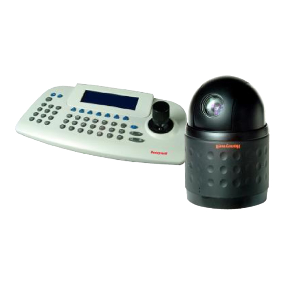
- Page 1 ScanDome llI Dome Camera HSDC-252 Series HSDC-362 Series HSDC-363 Series Operation & Programming Manual Please read this manual thoroughly before use and keep it handy for future reference. Rev.110303...
- Page 2 Warnings and Cautions WARNING TO REDUCE THE RISK OF FIRE OR ELECTRIC SHOCK, DO NOT EXPOSE THIS PRODUCT TO RAIN OR MOISTURE. DO NOT INSERT ANY METALLIC OBJECTS THROUGH THE VENTILATION GRILLS OR OTHER OPENINGS ON THE EQUIPMENT. CAUTION EXPLANATION OF GRAPHICAL SYMBOLS The lightning flash with arrowhead symbol, within an equilateral triangle, is intended to alert the user to the presence of uninsulated "dangerous voltage"...
- Page 3 FCC COMPLIANCE STATEMENT FCC INFORMATION: THIS EQUIPMENT HAS BEEN TESTED AND FOUND TO COMPLY WITH THE LIMITS FOR A CLASS A DIGITAL DEVICE, PURSUANT TO PART 15 OF THE FCC RULES. THESE LIMITS ARE DESIGNED TO PROVIDE REASONABLE PROTECTION AGAINST HARMFUL INTERFERENCE WHEN THE EQUIPMENT IS OPERATED IN A COMMERCIAL ENVIRONMENT.
- Page 4 IMPORTANT SAFEGUARDS 1. Read these instructions. 2. Keep these instructions. 3. Heed all warnings. 4. Follow all instructions. 5. Do not use this apparatus near water. 6. Clean only with dry cloth. 7. Do not block any ventilation openings. Install in accordance with the manufacturer's instructions.
-
Page 5: Table Of Contents
Table of Contents Chapter 1 — Introduction ........................7 1.1 Features..............................7 1.2 Typical System Configuration....................... 8 Chapter 2 — Installation and Configuration..................9 2.1 Unpacking the box........................... 9 2.2 Basic Configuration of ScanDome Camera System..............9 2.3 Principle of Termination........................10 2.4 Dome Camera Address (ID) ........................ - Page 6 3.4.1 FOCUS CONTROL (MENU => CAMERA => FOCUS CONTROL) ............29 3.4.2 WB (white balance) (MENU => CAMERA => WB CONTROL) ..............29 3.4.3 AE CONTROL (MENU => CAMERA => AE CONTROL)................30 3.4.4 BLC SETUP (MENU => CAMERA => BLC SETUP)...................30 3.4.5 MOTION SETUP (MENU => CAMERA =>MOTION SETUP) ..............31 3.4.6 SHARPNESS CONTROL (MENU =>...
-
Page 7: Chapter 1 - Introduction
Chapter 1 — Introduction 1.1 Features The ScanDome III dome camera features a high resolution Super HAD CCD imager for enhanced lowlight sensitivity. User friendly, on-screen pull-down menus and short-cuts make it easy to setup and program functions. System information aides trouble shooting by displaying the hardware and software version of the dome driver, baud rate, and protocol. -
Page 8: Typical System Configuration
1.2 Typical System Configuration Additional ScanDome joystick controllers and a variety of external switching devices such as multiplexers(MUX) and Digital Video Recorders (DVRs) may be incorporated to accommodate the needs from the small to large surveillance/security system. Figure 1 illustrates a small sample installation. -
Page 9: Chapter 2 - Installation And Configuration
Chapter 2 — Installation and Configuration 2.1 Unpacking the box The package contains the following. Quantity Component ScanDome III (Dome Camera) Instruction Manual (this document) Assembly Screws for Attaching ScanDome Plastic Anchor 3-Pin Connector 5-Pin Connector 8-Pin Cable Assembly 3-Bolt Spacer(Use for HSGN-502 and HSG-502F only) 2.2 Basic Configuration of ScanDome Camera System. -
Page 10: Principle Of Termination
The dome camera must be installed by qualified service personnel. Before installing the dome camera system this instruction manual must be read thoroughly and understood fully. Dome cameras must be set up properly before starting the installation. This involves properly setting configuration switches. -
Page 11: Dome Camera Address (Id)
S1:Dome1 port Termination ON DVR Termination ON SW2:Termination ON SW2:Termination ON S1:Dome1 port Termination ON DVR Termination ON SW2:Termination ON SW2:Termination ON SW2:Termination ON SW2:Termination ON S1:Dome1 port Termination ON S4:DVR port Termination ON DVR Termination ON DVR Termination ON SW2:Termination ON SW2:Termination ON S1:Dome1 port Termination ON... -
Page 12: Setting Protocols
Refer to Figures 6 for setting the dome camera address (ID) and protocol selection. Figure 6– Setting Dome Camera Address (ID) and Protocol 2.5 Setting Protocols A ScanDome camera is capable of negotiating with multiple protocols if the communication speed is matched (same baud rate i.e., 9600 bps). See Figure 7 for the appropriate protocol switch settings. - Page 13 RS-422: Connect TXA(Tx+) and TXB(Tx-) of the control device to RX+, RX- and TX+, TX- of the dome camera respectively. You need to select RS-422 mode at S4. RS-485 does not allow for a star connection layout. A splitter is required if a star connection layout is desired.
-
Page 14: Mounting The Dome Camera
2.7 Mounting the Dome Camera Once all DIP switches are set appropriately and all external connections are made, the dome camera can be mounted. The ScanDome camera is designed to mount on a structural surface supporting loads up to 5 Kg. - Page 15 RAM TEST CHECK NO. : OK! CHECK AAAA : OK! CHECK 5555 : OK! SCANDOMEIIIR Vx.xxx CAMERA TYPE xxxx WAIT DOME SETTING. INIT TILT ORIGIN SET OK INIT PAN ORIGIN SET OK INIT CAMERA SET OK On Screen Display in normal control mode Preset No.
-
Page 16: Chapter 3 - Program And Operation
Chapter 3 — Program and Operation Dome Camera Selection Before you start programming or operating a dome camera, you should make the dome camera be under control of the joystick controller. In other words, the dome camera that you want to effect changes must be currently selected. -
Page 17: Home Function (Menu =>Function => Home Function)
Locate the cursor on the FUNCTION item and then push the joystick to the right to enter FUNCTION menu. Function Home Function Preset Pattern Scan Tour Exit 3.1.1 HOME FUNCTION (MENU =>FUNCTION => HOME FUNCTION) After HOME FUNCTION item has been selected, follow the directions below to set HOME function. -
Page 18: Preset (Menu => Function => Preset Short Cut : Prst )
7. Pushing the Joystick down and twist the Joystick to CCW/CW (or push the stick to right/left) to set waiting time. 8. Locate the cursor on OPERATION option by pushing the Joystick down. Choose operation status Enable or Disable by pushing the Joystick to the right or to the left (or twist CCW/CW). -
Page 19: Pattern (Menu => Function => Pattern Or Shortcut: Ptrn)
M : Motion area 1(All), 2(Upper), 3(Lower), 4(Left), 5(Right), F(Free) Follow the steps below to program the Preset positions. 1. Select the camera number by pressing 0 ~9 and CAM. 2. Simply press PRST button to enter preset menu. ( MENU => FUNCTION => PRESET) 3. - Page 20 Pattern Setup Title 01 : xxxxxxxxxxxxxxxx 02 : xxxxxxxxxxxxxxxx 03 : xxxxxxxxxxxxxxxx 04 : xxxxxxxxxxxxxxxx TOTAL : Save And Exit Follow the steps below to program the Pattern: 1. Simply press the PTRN key. (or MENU => FUNCTION =>PATTERN) 2. Select the empty Pattern number to be programmed by pushing the Joystick Up or Down. If SEC column is not 000, then the selected No.
-
Page 21: Scan (Menu => Function => Scan Or Shortcut: Scan)
3.1.4 SCAN (MENU => FUNCTION => SCAN or Shortcut: SCAN) The Scan function supports up to 16 programmed section of angles at 8 programmable speeds. Scan Menu 01/16 SCAN 01 : AUTOSCAN01 Speed : 1~8/SLW/MID Start : 127.1, 027.0 : 157.7, 080.7 DIR. -
Page 22: Tour (Or Menu => Function => Tour, Short Cut: Tour)
8. Push the Joystick downward to select “SWAP” and set the swap by moving the Joystick left and right to select the swap ON or OFF. 9. Select Save and Exit by pushing the Joystick to the right. Press ESC to exit the program without saving. -
Page 23: Alarm (Menu => Alarm)
Follow the steps below to program the Tours: 1. Press MENU => FUNCTION => TOUR, Short Cut: TOUR MENU to display the main menu on the monitor. No. + SHFT+TOUR will open directly Tour No. 2. Choose an empty location of function by pushing the Joystick up or down. 3. - Page 24 Alarm Setup No Fun Out Hld Latch 01 P01 OFF OFF 001 02 048 OFF OFF 001 03 001 OFF OFF 001 04 --- OFF OFF 001 05 --- OFF OFF 001 06 --- OFF OFF 001 07 --- OFF OFF 001 08 --- OFF OFF 001 Save And Exit...
-
Page 25: Screen
3.3 SCREEN Pressing the MENU button on the keyboard controller, the following On-screen MAIN MENU will be shown on your monitor screen. Main Menu Function Alarm Screen Camera Setup Exit Locate the cursor on the SCREEN item and then push the joystick to the right to enter SCREEN menu. -
Page 26: Privacy Zone (Menu => Screen => Privacy Zone)
3.3.2 PRIVACY ZONE (MENU => SCREEN => PRIVACY ZONE) Locate the cursor on the PRIVACY ZONE item and then push the joystick to the right to enter the menu. Screen Menu Language Privacy Zone North Direction Zone Title Camera Title Exit This function disables the viewing of restricted areas for privacy reasons. -
Page 27: North Direction (Menu => Screen => North Direction)
7. Select the Save and Exit option by pushing the Joystick up or down. Save and exit the program by pushing the Joystick to the right. Press ESC to exit the program without saving. Press the HOME orOff button to delete programmed privacy zone. 3.3.3 NORTH DIRECTION (MENU =>... -
Page 28: Camera Title (Menu => Screen => Camera Title)
3. Twist the joystick handle on the No. column to enter zone title. You can select alphanumeric characters by rotating the handle. Move to the next character by pushing the Joystick to the right. To finish entering the title, push the Joystick down. 4. -
Page 29: Camera (Menu => Camera)
3.4 CAMERA (MENU => CAMERA) NOTE: The menu features will vary depending on the camera module installed in your dome camera. Camera Menu Focus Control WB Control AE Control BLC Setup Motion Setup Sharpness Digital Zoom Night Shot Camera Default Save And Exit 3.4.1 FOCUS CONTROL (MENU =>... -
Page 30: Ae Control (Menu => Camera => Ae Control)
MODE ATW / INDOOR / OUTDOOR / MWB / AWC (ONE PUSH) / AWC (AUTO) CONT AUTO / 0~255 (in MWB) / LOCK (in AWC (ONE PUSH)) Use the ATW mode for normal use. CONT modes are controllable only in AWC(ONE PUSH) and MWB Mode Push the Joystick to the right or left to change. -
Page 31: Motion Setup (Menu => Camera =>Motion Setup)
1) HSDC-252 Series, HSDC-362Series, HSDC-363Series BLC Setup : BLC BLOCK SET Level : 07 Exit : OFF, ON, AUTO, WDR, BMB BLC LEVEL : 0 ~ 20 WDR LEVEL : 0 ~ 20 BMB LEVEL : 0 ~ 20 Select BMB operated area depending on circumstance, for using BMB more effectively. Screen is divided 16 areas, each area is set separately. -
Page 32: Sharpness Control (Menu => Camera =>Shapeness)
User can decide sensitivity of motion detection OUTPUT : OFF / R01 / R02 . MOTION AREA SET : User can configure motion detection area. Area selection method is same to BMB area selection 3.4.6 SHARPNESS CONTROL (MENU => CAMERA =>SHAPENESS) The higher, the more enhanced edges in the picture. -
Page 33: Camera Default (Menu => Camera =>Camera Default)
3.4.9 CAMERA DEFAULT (MENU => CAMERA =>CAMERA DEFAULT) Returns all changed camera values to factory default . Camera Default Are You Sure : (Y/N) Yes : ENTER OR MENU KEY : ESC KEY 3.5 SETUP (MENU => SETUP) Setup Menu Flip : ON/OFF Speed... -
Page 34: Tilt Over Angle (Menu => Setup => Tilt Over Angle)
Panning Range Setup Right Limit : 000.0 Left Limit : 000.0 Enable : OFF/ON Swap Right Left Save And Exit When the dome camera is installed near a wall or corner, panning range can be limited by user. 3.5.5 TILT OVER ANGLE (MENU => SETUP => TILT OVER ANGLE) This option is used to set the limit of the horizontal view angle so that the trim ring or ceiling does not obstruct the horizontal image when zooming out (wide angle). -
Page 35: Factory Default (Menu => Setup => Factory Default)
AUTO CALIBRATION : The dome camera calibrates automatically when the deviation of dome position by force or vibration is detected. ( over 2 degrees ) 3.5.7 FACTORY DEFAULT (MENU => SETUP => FACTORY DEFAULT) Factory Default Are You Sure : (Y/N) Yes : ENTER OR MENU KEY : ESC KEY Programmed data go back to initial state as ex-factory... -
Page 36: Appendix A - Specifications
Appendix A — Specifications Video Camera(HSDC-252NA/PA) Image Sensor 1/4" Super HAD Color CCD (Sony) NTSC : 768x494 Approx. 380K pixels Picture elements : 752x582 Approx. 440K pixels Horizontal Resolution 520 lines(NTSC/PAL) 25x optical zoom with auto focus Lens 16x digital zoom(total 400x) F1.6 to F3.7, f=3.8mm to 95mm View angle Approx. - Page 37 Camera(HSDC-363N/P) Image Sensor 1/4" Super HAD Color CCD (Sony) NTSC : 768x494 Approx. 380K pixels Picture elements : 752x582 Approx. 440K pixels Horizontal Resolution 520 lines(NTSC/PAL) 36x optical zoom with auto focus Lens 16x digital zoom(total 576x) F1.6 to F4.5, f=3.4mm to 122.4mm View angle Approx.
- Page 38 Pattern Four patterns, 240 second On-Screen Display Displays camera ID and area name on screen Environment Operating temperature 0°C to 50°C (32°F to 122(F) Operating humidity 0 to 90%RH (non-condensing) Storage temperature -20°C to 60°C (4°F to 140°F) Specifications are subject to change without notice. Figure 10–...
-
Page 39: Appendix B - Troubleshooting
Appendix B — Troubleshooting If problems occur, verify the installation of the camera with the instructions in this manual. Isolate the problem from the equipments in the system and refer to the equipment manual for further information. Problem Solution Verify that power is connected to all pieces of equipment in the system. - Page 40 MEMO Honeywell Security Group Honeywell Co. Ltd. Printed in Korea...
Need help?
Do you have a question about the ScanDome III HSDC-252 Series and is the answer not in the manual?
Questions and answers