
Related Manuals for Honeywell ScanDome II HSDN-251NS/PS


Summary of Contents for Honeywell ScanDome II HSDN-251NS/PS
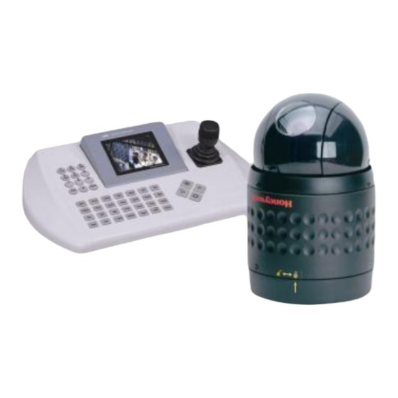
- Page 1 ScanDome ll Dome Camera HSDN-251NS/PS , HSDN-230NS/PS Operation & Programming Manual Please read this manual thoroughly before use and keep it handy for future reference. Rev.040602...
-
Page 2: Warnings And Cautions
Warnings and Cautions WARNING TO REDUCE THE RISK OF FIRE OR ELECTRIC SHOCK, DO NOT EXPOSE THIS PRODUCT TO RAIN OR MOISTURE. DO NOT INSERT ANY METALLIC OBJECTS THROUGH THE VENTILATION GRILLS OR OTHER OPENINGS ON THE EQUIPMENT. CAUTION EXPLANATION OF GRAPHICAL SYMBOLS The lightning flash with arrowhead symbol, within an equilateral triangle, is intended to alert the user to the presence of uninsulated "dangerous voltage"... -
Page 3: Fcc Compliance Statement
FCC COMPLIANCE STATEMENT FCC INFORMATION: THIS EQUIPMENT HAS BEEN TESTED AND FOUND TO COMPLY WITH THE LIMITS FOR A CLASS A DIGITAL DEVICE, PURSUANT TO PART 15 OF THE FCC RULES. THESE LIMITS ARE DESIGNED TO PROVIDE REASONABLE PROTECTION AGAINST HARMFUL INTERFERENCE WHEN THE EQUIPMENT IS OPERATED IN A COMMERCIAL ENVIRONMENT. -
Page 4: Important Safeguards
IMPORTANT SAFEGUARDS READ INSTRUCTIONS -- All the safety and operating POWER CORDS -- Do not allow anything to rest on the instructions should be read before the appliance is operated. power cord. Do not locate video monitor or equipment where the cord will be abused by persons walking on it. -
Page 5: Table Of Contents
Table of Contents Chapter 1 … Introduction ..............1 1.1 Features.................... 1 Chapter 2 … Installation And Configuration ........3 2.1 Package Contents................3 2.2 Basic Configuration Of Scandome II Dome Camera System ..4 2.3 Setting Unit For Termination .............. 5 2.4 Setting Address(Id) Of Dome Camera ........ - Page 6 3.9 Alarm....................17 3.10 Area Title ..................17 3.11 Privacy Zone ................. 18 3.12 Camera ..................20 Focus Control ......................20 WB(White Balance) Control ................... 21 AE(Auto Exposure) Control..................21 Line Lock Control....................22 Night Shot Menu ....................
-
Page 7: Chapter 1 - Introduction
Chapter 1 – Introduction 1.1 Features The ScanDome II Keyboard Controller and the ScanDome II dome camera make up the building blocks for any surveillance/security system. Using multiple Keyboard Controllers and multiple dome cameras, no place is too large for monitoring. Extensible and flexible architecture facilitates remote control functions for a variety of external switching devices such as multiplexers and DVRs. - Page 8 UP TO 255 MULTIPLEXER Alarm Input UP TO 8 <Sensor> UP TO 99 DVR <Siren> Alarm Output UP TO 4 <Flashing Light> <Master Keyboard> UP TO 32 CAMERA UP TO 3 Slave Keyboard Figure 1 • Typical System Configuration...
-
Page 9: Chapter 2 - Installation And Configuration
Chapter 2 – Installation and Configuration 2.1 Package Contents The package contains the following. “ “ “ “ “ “ “ “ “ 1 ScanDome II (Dome Camera) “ “ “ “ “ “ “ “ “ 1 Bubble Ring “... -
Page 10: Basic Configuration Of Scandome
2.2 Basic Configuration of ScanDome II Dome Camera System. PO W E R AC 24V U TP AW G # 24 SIR E N PO W ER AC 24V R S -485 HALF D U P LEX M O D E : TX+,TX- LIG H T ALARM O U TPU T S E N S O R... -
Page 11: Setting Unit For Termination
The dome camera must be installed by qualified service personnel in accordance with all local and federal electrical and building codes. The system should be installed according to Figures 2 through 8. Termination Switches KS D02H Address(ID) selection Switches Protocol selection Switches Figure 4•... -
Page 12: Setting Address(Id) Of Dome Camera
Cable for communication Branch Not allowed Without spliter /repeater Enable Termination (On) Enable Termination (On) Cable for communication Figure 6 Termination Diagram 2.4 Setting Address (ID) of Dome Camera To prevent damage, each dome camera must have a unique address (ID). When installing multiple dome cameras using a multiplexer, it is suggested that the dome camera address match the multiplexer port number. -
Page 13: Setting Protocol Of Dome Camera
2.5 Setting Protocol of Dome Camera If a dome camera is to be installed with a Scandome II keyboard controller, select F2 protocol. Consult service personnel if a dome camera is installed with device other than a keyboard controller. UNCTION S4-1 Enable Disable... -
Page 14: Connecting Wiring
2.6 Connecting Wiring 㿱 Connecting to the RS-485/ 422 The dome camera can be controlled remotely by an external device or control system, such as a control keyboard, using RS485 half-duplex , RS422 duplex or simplex serial communications signals. Connect Marked Rx+, Rx- to Tx+ and Tx- of the RS485 control system. If control system is RS422, connect Rx+(Tx+), Rx+(Tx-) and (Rx+), (Rx-) of the dome camera to Tx+, Tx- and (Rx+), (Rx-) of the control device respectively. - Page 15 RAM TEST CHECK NO. : OK! CHECK AAAA : OK! CHECK 5555 : OK! SCANDOME II Vx.xxx CAMERA TYPE xxxx WAIT DOME SETTING. INIT TILT ORGIN SET OK INIT PAN ORGIN SET OK INIT CAMERA SET OK...
-
Page 16: Selecting Dome Camera
Chapter 3 – Program and Operation 3.1 Selecting Dome Camera Before you program or operate a dome camera, you must select the dome camera by pressing the dome camera No. + CAM Example: Pressing 1 , 0 and CAM key sequentially will select dome camera 10. The selected dome camera ID will be displayed on the LCD monitor of the keyboard controller. -
Page 17: How To Control On-Screen Menu Utility
3.3 How to control On-Screen Menu Utility Action Function MENU Call on On-screen menu utility Go into the sub-menu items. Execute the command(exit) Joystick left or right Change value. Navigate through the menu items. Joystick up or down Navigate through the menu items. Joystick down Finish editing title. -
Page 18: Preset
3. Twist the Joystick to enter the title by scrolling through the alphanumeric characters and pushing the handle to the right or left to move to the next space. Press Enter key or push the Joystick down to finish title mode 4. - Page 19 If you need to view specific places routinely, you should program presets. A preset is a programmed video scene with automatic pan, tilt, zoom, focus and iris settings. Once programmed, entering the number and pressing a preset button on your controller automatically calls up the preset.
-
Page 20: Shortcut Preset Program
6. Enter the title for the preset position using the Joystick. (Rotate handle clockwise and counterclockwise or press Tele or Wide Key to scroll through the alphanumeric characters, push the handle to right or left to select next or previous digit.) 7. - Page 21 TOUR 01 : xxxxxxxxxxxxxxxx SCAN TYPE : NORMAL DWELL: 03 === === 003 === === === === A08 === === === === === === === T02 === 001 === === === === === === T08 === === === === === === === === === === === === === === === === === SAVE AND EXIT ( ESC TO CANCEL) PRESS FUNCTION KEY AND THEN ZOOM...
-
Page 22: Pattern
NOTE: Press the Home key at a programmed position to delete programmed function. In the Tour mode, in conjunction with preset and Auto Scan, you can make the camera travel from a preset position to another preset position at a specific speed. Example: Preset 001>002>003>004>005>006, Auto Scan 01 starts at preset 002, ends at preset 003, Auto Scan 02 starts at preset 005, ends at preset 006;... -
Page 23: Alarm
NOTE: If total recording time reaches 240 seconds, it will automatically stop for a moment and restart recording. Previous data will be overwritten. 3.9 Alarm (This menu shows on only specific model, Fifth Item of Main menu) ALARM SETUP NO PRI PRS IN HLD LATCH 001 OFF OFF 001 OFF OUT1... -
Page 24: Privacy Zone
AREA TITLE SETUP TITLE START 124.3 359.5 xxxxxxxxxxxxxxxx ===== ===== xxxxxxxxxxxxxxxx ===== ===== xxxxxxxxxxxxxxxx ===== ===== xxxxxxxxxxxxxxxx ===== ===== xxxxxxxxxxxxxxxx ===== ===== xxxxxxxxxxxxxxxx ===== ===== xxxxxxxxxxxxxxxx ===== ===== SAVE AND EXIT ( ESC TO CANCEL) HOLD DOWN CTRL KEY WHILE SELECTIONG SECTION Pages can be scrolled through by pushing the joystick to the Left or Right on the first or last column of the menu. - Page 25 PRIVACY ZONE SETUP TITLE METHOD xxxxxxxxxxxxxxxx BLOCK xxxxxxxxxxxxxxxx V.OFF xxxxxxxxxxxxxxxx NONE ==== xxxxxxxxxxxxxxxx NONE ==== xxxxxxxxxxxxxxxx NONE ==== xxxxxxxxxxxxxxxx NONE ==== xxxxxxxxxxxxxxxx NONE ==== xxxxxxxxxxxxxxxx NONE ==== SAVE AND EXIT ( ESC TO CANCEL) HOLD DOWN CTRL KEY WHILE SELECTION ZONE TO BE MASKED. 1.
-
Page 26: Camera
3.12 Camera (Eighth Item of Main menu) NOTE: The menu features will vary depending on the camera module installed in your dome camera. CAMERA SETUP FOCUS CONTROL WB CONTROL AE CONTROL LINE LOCK CONTROL SHARPNESS : 10 BACK LIGHT : OFF DIGITAL ZOOM : OFF/2X/4X/ MAX NIGHT SHOT CONTROL (optional) SAVE AND EXIT(ESC TO CANCEL) - Page 27 WB MENU MODE : ATW CONT : AUTO SAVE AND EXIT(ESC TO CANCEL) MODE ATW / INDOOR / OUTDOOR / MWB / AWC CONT AUTO/ 3200K / 5400K / 0-99 / LOCK, PUSH Use the ATW mode for normal use. CONT menu is controllable only in MWB and AWC modes.
-
Page 28: Night Shot Menu
㿱LINE LOCK CONTROL LINE LOCK MENU MODE : INTERNAL PHASE : EXIT (ESC TO EXIT) MODE INTERNAL / EXTERNAL Adjusts phase of picture with other PHASE 0~255 cameras in EXTERNAL mode. EXIT (ESC TO EXIT) 㿱NIGHT SHOT MENU ( 251NS/PS model only ) The NIGHT SHOT option removes the IR cutoff filter of the camera and makes the camera sensitive to near infrared. -
Page 29: Home Function Setup
CONFIGURATION MENU HOME FUNCTION SETUP OSD DISPLAY VIEW ANGLE SETUP INITIALIZE DATA ORIGIN OFFSET DOME RESET SYSTEM INFORMATION EXIT(ESC TO EXIT) 㿱HOME FUNCTION SETUP After a dome control menu item has been selected, follow the directions below to set the function. HOME FUNCTION SETUP HOME FUNCTION : NONE... - Page 30 㿱OSD DISPLAY DISPLAY SETUP CAMERA TITLE : XXXXXXX VIEW DIRECTION : OFF DOME OSD DISPLAY : ON AREA DISPLAY : OFF SAVE AND EXIT(ESC TO CANCEL) CAMERA TITLE VIEW DIRECTION : ON / OFF DOME OSD DISPLAY : ON / OFF AREA DISPLAY : ON / OFF 㿱...
- Page 31 When the dome camera is installed near wall, panning range could be programmed by user. PANNING RANGE MENU RIGHT LIMIT : 000.0 LEFT LIMIT : 000.0 ENABLE : OFF SWAP RIGHT/LEFT SAVE AND EXIT(ESC TO CANCEL) 㿱FLIP Allows the dome camera to automatically turn 180 degrees when the camera tilts to its lower position.
- Page 32 The offset value is still valid after all data is erased. The offset value can be zero only with default set of Offset origin menu. CAUTION: All the data in the selected dome camera will be lost unless you download the data into a safe place.
-
Page 33: Appendix A ... Specifications
Appendix A – Specifications Camera HSDN-251NS/PS Image Sensor 1/4" SONY Super HAD Color CCD (Sony) NTSC : 768x494 Approx. 380K pixels Picture elements PAL : 752x582 Approx. 410K pixels Horizontal Resolution 470 / 460 lines(NTST/PAL) 25x optical zoom with auto focus Lens 8x digital zoom F1.6 to F3.7, f=3.8mm to 95mm... - Page 34 General Certification CE EMC, FCC CLASS A Electrical Input Voltage 18 to 30 VAC; 24 VAC nominal, built-in power-line surge Power voltage Nominal 24 VAC/VDC 850mA maximum, Power Consumption Maximum 20W Alarm Output 4 Normal relays 24 VDC/1A Max (selectable NC/NO) Alarm Input 8 Normal dry contact (selectable NC/NO) Control...
-
Page 35: Appendix B
Appendix B – Troubleshooting If problems occur, verify the installation of the camera with the instructions in this manual and with other operating equipment. Isolate the problem to the specific piece of equipment in the system and refer to the equipment manual for further information. Problem Possible Solution Verify that power is connected to all pieces of... -
Page 36: Appendix C ... Glossary
Appendix C – Glossary Alarm Actions The assigned responses for the dome camera when inputs change from normal to abnormal states. The dome may run a Preset, Pattern, or have no assigned action for each of the four dome inputs. The dome may also send alarm states to the host controller for processing. See also Input and Normal Input State. -
Page 37: Line Lock
detectors and smoke detectors. IR Mode A feature of the camera that permits manual or automatic switching between color and IR (black-and-white) operation. When IR mode is active, clearer images may be obtained under low-light conditions. Line Lock Allows you to phase lock the video with the AC power line. When line lock is enabled, it prevents vertical video rolling when switching multiple cameras to a single monitor. -
Page 38: Privacy Zones
Privacy Zones Masked areas of the dome camera's viewing area. These masks prevent operators of the surveillance system from viewing these designated zones. The Privacy Zones move in relation to the dome camera█s pan/tilt position. In addition, the apparent size of the Privacy Zone adjusts automatically as the lens zooms in or out.
Need help?
Do you have a question about the ScanDome II HSDN-251NS/PS and is the answer not in the manual?
Questions and answers