Table of Contents
Advertisement
Quick Links
Advertisement
Table of Contents

Related Manuals for Supermicro X12SPG-NF


Summary of Contents for Supermicro X12SPG-NF
- Page 1 X12SPG-NF USER'S MANUAL Revision 1.0...
- Page 2 State of California, USA. The State of California, County of Santa Clara shall be the exclusive venue for the resolution of any such disputes. Supermicro's total liability for all claims will not exceed the price paid for the hardware product.
- Page 3 The Supermicro X12SPG-NF supports a 3rd Generation Intel® Xeon Scalable Processor with up to 40 cores and a TDP of 270W. Built with the Intel C621A chipset, the X12SPG-NF supports 2TB of ECC RDIMM/LRDIMM and RDIMM/LRDIMM 3DS DDR4 memory with speeds of up to 3200MHz, SATA 3.0 ports, M.2 slots, AIOM, and a Trusted Platform Module (TPM)
- Page 4 Super X12SPG-NF User's Manual Contacting Supermicro Headquarters Address: Super Micro Computer, Inc. 980 Rock Ave. San Jose, CA 95131 U.S.A. Tel: +1 (408) 503-8000 Fax: +1 (408) 503-8008 Email: marketing@supermicro.com (General Information) support@supermicro.com (Technical Support) Website: www.supermicro.com Europe Address: Super Micro Computer B.V.
-
Page 5: Table Of Contents
Preface Table of Contents Chapter 1 Introduction 1.1 Important Links ........................8 Quick Reference .......................11 Quick Reference Table ......................12 Motherboard Features .......................13 1.2 Processor and Chipset Overview ..................16 1.3 Special Features ........................16 Recovery from AC Power Loss ..................16 1.4 System Health Monitoring ....................16 Onboard Voltage Monitors ....................16 Fan Status Monitor with Firmware Control ...............17 Environmental Temperature Control .................17... - Page 6 Super X12SPG-NF User's Manual Tools Needed ........................28 Location of Mounting Holes ....................28 Installing the Motherboard....................29 2.4 Memory Support and Installation ..................30 Memory Support ........................30 DDR4 Memory Support .....................30 General Guidelines for Optimizing Memory Performance ..........31 DIMM Installation ......................32 DIMM Removal .........................32 2.5 Rear I/O Ports ........................33...
- Page 7 Preface 4.1 Introduction .........................54 4.2 Main Setup .........................55 4.3 Advanced ..........................57 4.4 Event Logs .........................89 4.5 IPMI ............................91 4.6 Security ..........................94 4.7 Boot ..........................100 4.8 Save & Exit ........................103 Appendix A Software Appendix B Standardized Warning Statements...
-
Page 8: Chapter 1 Introduction
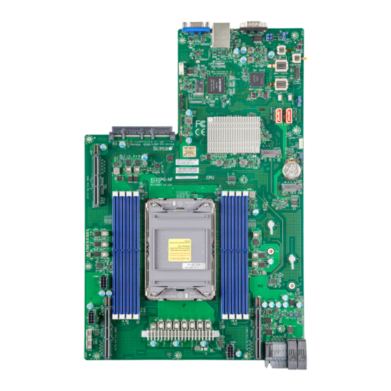
Introduction Congratulations on purchasing your computer motherboard from an industry leader. Supermicro motherboards are designed to provide you with the highest standards in quality and performance. Note: This motherboard was designed to be a part of an integrated server solution. - Page 9 Chapter 1: Introduction Figure 1-1. Motherboard Image Note: All graphics shown in this manual were based upon the latest PCB revision available at the time of publication of the manual. The motherboard you received may or may not look exactly the same as the graphics shown in this manual.
- Page 10 Super X12SPG-NF User's Manual Figure 1-2. Motherboard Layout (not drawn to scale) JWD1 JUART1 COM1 JUART2 JPFR1 JWD1:WATCH DOG 1-2:RST 2-3:NMI BMC_LAN USB0/1(3.2 Gen 1) JIPMB1 JTPM1 JTPM1: TPM/PORT80 JDBG2 JSD1 JSD2 JDBG1 JSD1:SATA DOM POWER JSD2:SATA DOM POWER S-SATA0...
-
Page 11: Quick Reference
JAIOM1 JSXB1-1 JSXB1-1 AIOM1 PCI-E4.0x8 LEDHDD LEDHDD M.2-H_2 BIOS JPME2 LICENSE JPME2 M2_CONN_2 AIOM1 JBT1 CMOS CLEAR IPMI CODE BAR CODE X12SPG-NF M.2-H_1 JSXB1-2 M.2-H_1 REV:1.01 DESIGNED IN USA M2_CONN_1 DIMMC1 DIMMD1 DIMMG1 MH13 MH13 DIMMH1 DIMMA1 DIMME1 DIMMB1 DIMMF1... -
Page 12: Quick Reference Table
Super X12SPG-NF User's Manual Quick Reference Table Jumper Description Default Setting JBT1 CMOS Clear Open (Normal) JPME2 ME Manufacturing Mode Pins 1-2 (Normal) Description Status LEDBMC BMC Heartbeat Blinking Green: Device Working LEDHDD HDD Activity LED Blinking Green: HDD Active... -
Page 13: Motherboard Features
Up to 2TB of ECC RDIMM/LRDIMM and RDIMM/LRDIMM 3DS DDR4 memory with speeds of up to 3200MHz in eight memory slots DIMM Size • Up to 256GB Note: For the latest CPU/memory updates, please refer to our website at http://www.supermicro.com/products/ motherboard. Chipset • Intel C621A Expansion Slots •... - Page 14 Note 1: The CPU maximum thermal design power (TDP) is subject to chassis and heatsink cooling restrictions. For proper thermal management, please check the chas- sis and heatsink specifications for proper CPU TDP sizing. Note 2: For BMC configuration instructions, please refer to the Embedded BMC Con- figuration User's Guide available at http://www.supermicro.com/support/manuals/.
- Page 15 Chapter 1: Introduction Figure 1-3. System Block Diagram ChanF ChanB ChanA ChanE VR13 HC ChanD ChanH 7+1 PHASE ChanG ChanC CPU#1 PECI: 30 SOCKET ID: 0 #1, 2, 3 #0A #0B 3*PCI-E X16 , Gen4 PCI-E X8 , Gen4 (2* NVME) PCI-E X8 , Gen4 (Reversal) AIOM...
-
Page 16: Processor And Chipset Overview
1.2 Processor and Chipset Overview Built upon the functionality and capability of the 3rd Generation Intel Xeon Scalable Processor and the Intel C621A chipset, the X12SPG-NF motherboard provides system performance, power efficiency, and feature sets to address the needs of next-generation computer users. -
Page 17: Onboard Voltage Monitors
Plug and Play, and an operating system-independent interface for configuration control. ACPI leverages the Plug and Play BIOS data structures, while providing a processor architecture-independent implementation that is compatible with appropriate Windows operating systems. For detailed information regarding OS support, please refer to the Supermicro website. -
Page 18: Power Supply
1.7 Serial Port The X12SPG-NF motherboard supports one serial communication connection. COM1 can be used for input/output. The UART provides legacy speeds with a baud rate of up to 115.2 Kbps as well as an advanced speed with baud rates of 250 K, 500 K, or 1 Mb/s, which support... -
Page 19: Chapter 2 Installation
Chapter 2: Installation Chapter 2 Installation 2.1 Static-Sensitive Devices Electrostatic Discharge (ESD) can damage electronic com ponents. To avoid damaging your system board, it is important to handle it very carefully. The following measures are generally sufficient to protect your equipment from ESD. Precautions •... -
Page 20: Processor And Heatsink Installation
Thermal grease is pre-applied on a new heatsink. No additional thermal grease is needed. • Refer to the Supermicro website for updates on processor support. • All graphics in this manual are for illustrations only. Your components may look different. -
Page 21: Overview Of The Processor Carrier Assembly
Chapter 2: Installation Overview of the Processor Carrier Assembly The processor carrier assembly contains the 3rd Generation Intel Xeon Scalable Processor and a processor carrier. 1. Processor 2. Processor Carrier Overview of the CPU Socket The CPU socket is protected by a plastic protective cover. 1. -
Page 22: Overview Of The Processor Heatsink Module
Super X12SPG-NF User's Manual Overview of the Processor Heatsink Module The Processor Heatsink Module (PHM) contains a heatsink, a processor carrier, and the processor. 1. Heatsink with Thermal Grease 2. Processor Carrier 3. Processor Processor Heatsink Module... -
Page 23: Creating The 3Rd Generation Intel Xeon Scalable Processor Carrier Assembly
CPU Pin 1 Processor Carrier Assembly Note: The following CPU carriers have been successfully tested in our labs and are available from Supermicro. Please order the CPU carriers with the CPU heatsink. SKT-1205L-P4IC-FXC Intel 3rd Generation Xeon Scalable Processors... -
Page 24: Assembling The Processor Heatsink Module
Super X12SPG-NF User's Manual Assembling the Processor Processor Carrier Assembly (Upside Down) Heatsink Module After creating the processor carrier assembly for the processor, mount it onto the heatsink to create the processor heatsink module (PHM): 1. Note the label on top of the heatsink, which marks the heatsink mounting holes as 1, 2, 3, and 4. -
Page 25: Preparing The Cpu Socket For Installation
Chapter 2: Installation Preparing the CPU Socket for Installation This motherboard comes with a plastic protective cover installed on the CPU socket. Remove it from the socket to install the Processor Heatsink Module (PHM). Gently pull up one corner of the plastic protective cover to remove it. -
Page 26: Installing The Processor Heatsink Module
Super X12SPG-NF User's Manual Installing the Processor Heatsink Module After assembling the Processor Heatsink Module (PHM), install it onto the CPU socket: 1. Align hole 1 of the heatsink with the printed triangle on the CPU socket. See the left image below. -
Page 27: Removing The Processor Heatsink Module
Chapter 2: Installation Removing the Processor Heatsink Module Remove the screws in the sequence of 4, 3, 2, 1 Before removing the processor heatsink module (PHM) from the motherboard, shut down the system and then unplug the AC power cord from all power supplies. -
Page 28: Motherboard Installation
Super X12SPG-NF User's Manual 2.3 Motherboard Installation All motherboards have standard mounting holes to fit different types of chassis. Make sure that the locations of all the mounting holes for both the motherboard and the chassis match. Although a chassis may have both plastic and metal mounting fasteners, metal ones are highly recommended because they ground the motherboard to the chassis. -
Page 29: Installing The Motherboard
Chapter 2: Installation Installing the Motherboard 1. Install the I/O shield into the back of the chassis, if applicable. 2. Locate the mounting holes on the motherboard. See the previous page for the location. 3. Locate the matching mounting holes on the chassis. Align the mounting holes on the motherboard against the mounting holes on the chassis. -
Page 30: Memory Support And Installation
Memory Support The X12SPG-NF supports up to 2TB of ECC RDIMM/LRDIMM and RDIMM/LRDIMM 3DS DDR4 memory with speeds of up to 3200MHz in eight memory slots. Refer to the table below for the recommended DIMM population order. -
Page 31: General Guidelines For Optimizing Memory Performance
JRK1 LEDPWR JAIOM1 JRK1:RAID KEY JSXB1-1 AIOM1 PCI-E4.0x8 LEDHDD M.2-H_2 BIOS LICENSE JPME2 M2_CONN_2 JBT1 CMOS CLEAR IPMI CODE BAR CODE X12SPG-NF M.2-H_1 REV:1.01 DESIGNED IN USA M2_CONN_1 MH13 MH14 MH11 JPWR3 MH12 JPWR2 JSXB2-1 JSXB3-1 FAN2 VRM_HS JMP2 JMP1... -
Page 32: Dimm Installation
Super X12SPG-NF User's Manual DIMM Installation JWD1 JUART1 COM1 JUART2 JPFR1 JWD1:WATCH DOG 1-2:RST 1. Insert DIMM modules in the following 2-3:NMI BMC_LAN USB0/1(3.2 Gen 1) JIPMB1 order: DIMMC1, DIMMD1, DIMMA1, JTPM1 JTPM1: TPM/PORT80 DIMMB1, DIMMG1, DIMMH1, DIMME1, JDBG2 JSD1... -
Page 33: Rear I/O Ports
LEDPWR JRK1 JAIOM1 JRK1:RAID KEY JSXB1-1 AIOM1 PCI-E4.0x8 LEDHDD M.2-H_2 BIOS LICENSE JPME2 M2_CONN_2 JBT1 CMOS CLEAR IPMI CODE BAR CODE X12SPG-NF M.2-H_1 REV:1.01 DESIGNED IN USA M2_CONN_1 MH13 MH14 MH11 JPWR3 MH12 JPWR2 JSXB2-1 JSXB3-1 FAN2 VRM_HS JMP2 JMP1... - Page 34 Super X12SPG-NF User's Manual VGA Port A video (VGA) port is located on the I/O back panel. Refer to the board layout below for the location. COM Port There is one COM connection on this motherboard. COM1 is located on the I/O back panel.
- Page 35 JRK1 LEDPWR JAIOM1 JRK1:RAID KEY JSXB1-1 AIOM1 PCI-E4.0x8 LEDHDD M.2-H_2 BIOS LICENSE JPME2 M2_CONN_2 JBT1 CMOS CLEAR IPMI CODE BAR CODE X12SPG-NF M.2-H_1 REV:1.01 DESIGNED IN USA M2_CONN_1 MH13 MH14 MH11 JPWR3 MH12 JPWR2 JSXB2-1 JSXB3-1 FAN2 VRM_HS JMP2 JMP1...
- Page 36 Super X12SPG-NF User's Manual Universal Serial Bus (USB) Ports There are two USB 3.2 Gen 1 ports (USB1/2) on the I/O back panel. Back Panel USB 1/2 (3.2 Gen 1) Pin Definitions Pin# Definition Pin# Definition VBUS Power USB_N USB_P...
- Page 37 LEDPWR JRK1 JAIOM1 JRK1:RAID KEY JSXB1-1 AIOM1 PCI-E4.0x8 LEDHDD M.2-H_2 BIOS LICENSE JPME2 M2_CONN_2 JBT1 CMOS CLEAR IPMI CODE BAR CODE X12SPG-NF M.2-H_1 REV:1.01 DESIGNED IN USA M2_CONN_1 MH13 MH14 MH11 JPWR3 MH12 JPWR2 JSXB2-1 JSXB3-1 FAN2 VRM_HS JMP2 JMP1...
-
Page 38: Connectors
Super X12SPG-NF User's Manual 2.6 Connectors Power Connections Main Power and GPU Power Connectors JPWR1 is the 8-pin power connector used to provide power to the motherboard while the 8-pin GPU power connectors JPWR2 and JPWR3 can be connected to power the GPU card. These power connectors meet the SSI EPS 12V specification. -
Page 39: Headers
Port 80 connection. Use this header to enhance system performance and data security. Refer to the table below for pin definitions. Please go to the following link for more information on the TPM: http://www.supermicro.com/manuals/other/TPM.pdf. Trusted Platform Module Header Pin Definitions... - Page 40 Super X12SPG-NF User's Manual Intel RAID Key Header The JRK1 header allows you to enable RAID functions for NVMe connections. Refer to the table below for pin definitions. Intel RAID Key Header Pin Definitions Pin# Defintion PU 3.3V Stdby PCH RAID KEY 1.
- Page 41 This motherboard has two SATA 3.0 ports (S-SATA0, SATA1). S-SATA0 and S-SATA1 can be used with Supermicro SuperDOM's SATA DOM connectors with power pins built in, and do not require external power cables. Supermicro SuperDOMs are backward compatible with regular SATA HDDs or SATA DOMs that need external power cables.
-
Page 42: Jumper Settings
Super X12SPG-NF User's Manual 2.7 Jumper Settings How Jumpers Work To modify the operation of the motherboard, jumpers can be used to choose between optional settings. Jumpers create shorts between two pins to change the function of the connector. Pin 1 is identified with a square solder pad on the printed circuit board. - Page 43 JRK1 LEDPWR JAIOM1 JRK1:RAID KEY JSXB1-1 AIOM1 PCI-E4.0x8 LEDHDD M.2-H_2 BIOS LICENSE JPME2 M2_CONN_2 JBT1 CMOS CLEAR IPMI CODE BAR CODE X12SPG-NF M.2-H_1 REV:1.01 DESIGNED IN USA M2_CONN_1 MH13 MH14 MH11 JPWR3 MH12 JPWR2 JSXB2-1 JSXB3-1 FAN2 JMP1 VRM_HS JMP2...
-
Page 44: Led Indicators
Super X12SPG-NF User's Manual 2.8 LED Indicators Onboard Power LED LEDPWR is the onboard Power LED. When this LED is on, the system is on. Turn off the system and unplug the power cord before removing or installing components. Refer to the table below for more information. - Page 45 LEDPWR JRK1 JAIOM1 JRK1:RAID KEY JSXB1-1 AIOM1 PCI-E4.0x8 LEDHDD M.2-H_2 BIOS LICENSE JPME2 M2_CONN_2 JBT1 CMOS CLEAR IPMI CODE BAR CODE X12SPG-NF M.2-H_1 REV:1.01 DESIGNED IN USA M2_CONN_1 MH13 MH14 MH11 JPWR3 MH12 JPWR2 JSXB2-1 JSXB3-1 FAN2 VRM_HS JMP2 JMP1...
-
Page 46: Chapter 3 Troubleshooting
Super X12SPG-NF User's Manual Chapter 3 Troubleshooting 3.1 Troubleshooting Procedures Use the following procedures to troubleshoot your system. If you have followed all of the procedures below and still need assistance, refer to the ‘Technical Support Procedures’ and/ or ‘Returning Merchandise for Service’ section(s) in this chapter. Always disconnect the AC power cord before adding, changing or installing any non hot-swap hardware components. -
Page 47: System Boot Failure
Chapter 3: Troubleshooting System Boot Failure If the system does not display Power-On-Self-Test (POST) or does not respond after the power is turned on, do the following: 1. Check the screen for an error message. 2. Clear the CMOS settings by unplugging the power cord and contacting both pads on the CMOS clear jumper (JBT1). -
Page 48: When The System Becomes Unstable
Super X12SPG-NF User's Manual When the System Becomes Unstable A. If the system becomes unstable during or after OS installation, check the following: 1. CPU/BIOS support: Make sure that your CPU is supported and that you have the latest BIOS installed in your system. - Page 49 Chapter 3: Troubleshooting 6. To find out if a component is good, swap this component with a new one to see if the system will work properly. If so, then the old component is bad. You can also install the component in question in another system.
-
Page 50: Technical Support Procedures
Before contacting Technical Support, please take the following steps. Also, please note that as a motherboard manufacturer, Supermicro also sells motherboards through its channels, so it is best to first check with your distributor or reseller for troubleshooting services. They should know of any possible problems with the specific system configuration that was sold to you. -
Page 51: Frequently Asked Questions
Updated BIOS files are located on our website at http:// www.supermicro.com/ResourceApps/BIOS_IPMI_Intel.html. Please check our BIOS warning message and the information on how to update your BIOS on our website. Select your motherboard model and download the BIOS file to your computer. Also, check the current BIOS revision to make sure that it is newer than your BIOS before downloading. -
Page 52: Battery Removal And Installation
Super X12SPG-NF User's Manual 3.4 Battery Removal and Installation Battery Removal To remove the onboard battery, follow the steps below: 1. Power off your system and unplug your power cable. 2. Locate the onboard battery as shown below. 3. Using a tool such as a pen or a small screwdriver, push the battery lock outwards to unlock it. -
Page 53: Returning Merchandise For Service
For faster service, you can also request a RMA authorization online (http://www.supermicro. com/RmaForm/). This warranty only covers normal consumer use and does not cover damages incurred in shipping or from failure due to the alternation, misuse, abuse or improper maintenance of products. -
Page 54: Chapter 4 Uefi Bios
Super X12SPG-NF User's Manual Chapter 4 UEFI BIOS 4.1 Introduction This chapter describes the AMIBIOS™ Setup utility for the motherboard. The BIOS is stored on a chip and can be easily upgraded using a flash program. Note: Due to periodic changes to the BIOS, some settings may have been added or deleted and might not yet be recorded in this manual. -
Page 55: Main Setup
Note: The time is in the 24-hour format. For example, 5:30 P.M. appears as 17:30:00. The date's default value is the BIOS build date after RTC reset. Supermicro X12SPG-NF BIOS Version This feature displays the version of the BIOS ROM used in the system. - Page 56 Super X12SPG-NF User's Manual Memory Information Total Memory This feature displays the total size of memory available in the system.
-
Page 57: Advanced
Chapter 4: BIOS 4.3 Advanced Use the arrow keys to select the Advanced menu and press <Enter> to access the menu features. Warning: Take caution when changing the Advanced settings. An incorrect value, a very high DRAM frequency, or an incorrect DRAM timing setting may make the system unstable. When this occurs, revert to default manufacturer settings. - Page 58 Super X12SPG-NF User's Manual Wait For "F1" If Error Use this feature to force the system to wait until the "F1" key is pressed if an error occurs. The options are Disabled and Enabled. INT19 (Interrupt 19) Trap Response Interrupt 19 is the software interrupt that handles the boot disk function. When this feature is set to Immediate, the ROM BIOS of the host adapters will "capture"...
- Page 59 Chapter 4: BIOS Power Button Function This feature controls how the system shuts down when the power button is pressed. Select 4 Seconds Override for you to power off the system after pressing and holding the power button for four seconds or longer. Select Instant Off to instantly power off the system as soon as you press the power button.
- Page 60 Super X12SPG-NF User's Manual Hardware Prefetcher If set to Enable, the hardware prefetcher prefetches streams of data and instructions from the main memory to the L2 cache to improve CPU performance. The options are Disable and Enable. Adjacent Cache Prefetch The CPU prefetches the cache line for 64 bytes if this feature is set to Disabled.
- Page 61 Chapter 4: BIOS AES-NI Select Enable to use the Intel Advanced Encryption Standard (AES) New Instructions (NI) to ensure data security. The options are Disable and Enable. TME, TME-MT, TDX Total Memory Encryption Use this feature to enable or disable total memory encryption. The options are Disabled and Enabled.
- Page 62 Super X12SPG-NF User's Manual Intel SST-PP Use this feature to select the base frequency conditions for SST-PP. The options are Base, Config 3, and Config 4. AVX-P1 Use this feature to select the AVX-P1 level. The options are Normal, Level 1, and Level 2.
- Page 63 Chapter 4: BIOS Hardware PM State Control Hardware P-States This setting allows you to select between OS and hardware-controlled P-states. Select- ing Native Mode allows the OS to choose a P-state. Selecting Out of Band Mode allows the hardware to autonomously choose a P-state without OS guidance. Selecting Native Mode with No Legacy Support functions as Native Mode with no support for older hard- ware.
- Page 64 Super X12SPG-NF User's Manual CPU T State Control Software Controlled T-States Use this feature to enable Software Controlled T-States. The options are Disable and Enable. *If the feature above is set to Enable, the next feature is available for configuration: T-State Throttle Level Use this feature to enable or disable CPU throttling, which reduces power consumption.
- Page 65 Chapter 4: BIOS Link L0p Enable Select Enable for the QPI to enter the L0p state for power saving. The options are Dis- able, Enable, and Auto. Link L1 Enable Select Enable for the QPI to enter the L1 state for power saving. The options are Dis- able, Enable, and Auto.
- Page 66 Super X12SPG-NF User's Manual PCIe Remote P2P Relaxed Ordering Enable peer-to-peer relaxed ordering to optimize system performance. The options are Disable and Enable. Stale AtoS Use this feature to enable or disable Stale A to S optimization. There are three states in the in-memory directory: invalid (I), snoopAll (A), and shared (S).
- Page 67 Chapter 4: BIOS Data Scrambling for DDR4 Use this feature to enable or disable data scrambling for DDR4 memory. The options are Disable and Enable. 2x Refresh Enable Use this feature to enable 2x memory refresh support to enhance memory performance. The options are Auto, Disable, and Enable.
- Page 68 Super X12SPG-NF User's Manual IIO Configuration CPU1 Configuration IOU0/1/3/4 (IIO PCIe Port 1/2/4/5) Use this feature to configure the bifurcation setting for the PCIe port. The options are Auto, x4x4x4x4, x4x4x8, x8x4x4, x8x8, and x16. NVMe0/NVMe1 Link Speed Use this feature to select the link speed for the PCIe port.
- Page 69 Chapter 4: BIOS PCI-E Port Max Payload Size Selecting Auto for this feature enables the motherboard to automatically detect the maximum Transaction Layer Packet (TLP) size for the connected PCIe device, allowing for maximum I/O efficiency. Selecting 128B or 256B designates maximum packet size of 128 or 256.
- Page 70 Super X12SPG-NF User's Manual Intel(R) VMD Technology NVMe Mode Switch Use this feature to select the NVMe mode switch. The options are Manual, VMD, and Auto. *If the feature above is set to Manual, the next menu is available for configu-...
- Page 71 Chapter 4: BIOS AIOM1 PCI-E 4.0 x8 VMD Use this feature to enable or disable AIOM1 for this port. The options are Disable and Enable. Hot Plug Capable Use this feature to enable or disable hot plug for this port. The options are Dis- able and Enable.
- Page 72 Super X12SPG-NF User's Manual VMD Config for IOU 4 Enable/Disable VMD Use this feature to enable or disable the volume management device for this stack. The options are Disable and Enable. *If the feature above is set to Enable, the following features are available for...
- Page 73 Chapter 4: BIOS Port 60/64 Emulation This feature allows legacy I/O support for USB devices like mice and keyboards. The options are Disabled and Enabled. PCIe PLL SSC Use this feature to enable or disable PCIe PLL SSC. The options are Disabled and Enabled. Port 61h Bit-4 Emulation Select Enabled to enable the emulation of Port 61h bit-4 toggling in System Management Mode (SMM).
- Page 74 Super X12SPG-NF User's Manual Support Aggressive Link Power Management When this feature is set to Enable, the SATA AHCI controller manages the power usage of the SATA link. The controller puts the link in a low power mode during extended periods of I/O inactivity and then returns the link to an active state when I/O activity resumes.
- Page 75 Chapter 4: BIOS sSATA RAID Option ROM/UEFI Driver Select UEFI to load the EFI driver for system boot. Select Legacy to load a legacy driver for system boot. The options are Disable, EFI, and Legacy. S-SATA0/S-SATA1 This feature displays the information detected on the installed SATA drive on the particular SATA port.
- Page 76 Super X12SPG-NF User's Manual Media Detect Count Use this option to specify the number of times media is checked. Press "+" or "-" on your keyboard to change the value. The default setting is 1. PCIe/PCI/PnP Configuration PCI Bus Driver Version...
- Page 77 Chapter 4: BIOS MMCFG Base Use this feature to select the low base address for PCIe adapters to increase base memory. The options are 1G, 1.5G, 1.75G, 2G, 2.25G, 3G, and Auto. NVMe Firmware Source The feature determines which type of NVMe firmware should be used in your system. The options are Vendor Defined Firmware and AMI Native Support.
- Page 78 Super X12SPG-NF User's Manual *If the feature above is set to Disabled or PXE, the following feature is available for configuration: AOC-ATG-i2T LAN2 OPROM Use this feature to select which firmware type to be loaded for the add-on card in this slot.
- Page 79 Chapter 4: BIOS Serial Port 2 Select Enabled to enable the selected onboard serial port. The options are Disabled and Enabled. Device Settings This feature displays the status of the serial port. Change Settings This feature specifies the base I/O port address and the Interrupt Request address of the serial port.
- Page 80 Super X12SPG-NF User's Manual Data Bits Use this feature to set the data transmission size for Console Redirection. The options are 7 Bits and 8 Bits. Parity A parity bit can be sent along with regular data bits to detect data transmission errors. Select Even if the parity bit is set to 0, and the number of 1s in data bits is even.
- Page 81 Chapter 4: BIOS Redirection After BIOS POST Use this feature to enable or disable legacy console redirection after BIOS POST. When set to Bootloader, legacy console redirection is disabled before booting the OS. When set to Always Enable, legacy console redirection remains enabled when booting the OS. The options are Always Enable and Bootloader.
- Page 82 Super X12SPG-NF User's Manual Stop Bits A stop bit indicates the end of a serial data packet. Select 1 Stop Bit for standard serial data communication. Select 2 Stop Bits if slower devices are used. The options are 1 and 2.
- Page 83 Chapter 4: BIOS Console Redirection EMS (Emergency Management Services) Select Enabled to use a COM port selected by you for EMS Console Redirection. The options are Enabled and Disabled. *If the feature above is set to Enabled, the following features are available for configuration: EMS Console Redirection Settings This feature allows you to specify how the host computer exchanges data with the client...
- Page 84 Super X12SPG-NF User's Manual ACPI Settings NUMA Use this feature to enable or disable Non-Uniform Memory Access (NUMA), a feature that improves memory-to-processor communication and performance. The options are Disabled and Enabled. UMA-Based Clustering Use this feature to enable or disable Uniform Memory Access (UMA) clustering. The options are Disable (All2All) and Hemishpere (2-clusters).
- Page 85 Select Enabled to allow SID authentication be performed in TCG Storage devices. The options are Enabled and Disabled. SMCI BIOS-Based TPM Provision Support Use this feature to enable the Supermicro TPM Provision support. The options are Disabled and Enabled. TXT Support Intel Trusted Execution Technology (TXT) helps protect against software-based attacks and ensures protection, confidentiality, and integrity of data stored or created on the system.
- Page 86 Super X12SPG-NF User's Manual HTTP Boot Configuration HTTP Boot Configuration HTTP Boot Policy Use this feature to select the boot policy. The options are Apply to all LANs, Apply to each LAN, and Boot Priority #1 instantly. HTTPS Boot Checks Hostname Use this feature to select whether HTTPS Boot checks the hosname of TLS certificates matches the hosname provided by the remote server.
- Page 87 Chapter 4: BIOS TimeZone Use this feature to select the current time zone TCG Nvme KMS Policy Use this feature to select the Trusted Computing Group (TCG) NVMe KMS policy. The options are Normal Unlock, Do Nothing, Reset All Devices, and Delete Key Id List. TCG Nvme KMS Retry Count Use this feature to select the number of attempts of test connections to the Key Management Server.
- Page 88 Super X12SPG-NF User's Manual Server CA Configuration Enroll Certification Enroll Certification Using File Use this feature to enroll certification from a file. Certification GUID Use this feature to input the certification GUID. Commit Changes and Exit Use this feature to save all changes and exit TLS settings.
-
Page 89: Event Logs
Chapter 4: BIOS 4.4 Event Logs Use this menu to configure Event Log settings. Change SMBIOS Event Log Settings Enabling/Disabling Options SMBIOS Event Log Change this feature to enable or disable all features of the SMBIOS Event Logging during system boot. The options are Disabled and Enabled. Erasing Settings Erase Event Log If No is selected, data stored in the event log will not be erased. - Page 90 Super X12SPG-NF User's Manual SMBIOS Event Log Standard Settings Log System Boot Event This option toggles the System Boot Event logging to enabled or disabled. The options are Disabled and Enabled. MECI The Multiple Event Count Increment (MECI) counter counts the number of occurrences that a duplicate event must happen before the MECI counter is incremented.
-
Page 91: Ipmi
Chapter 4: BIOS 4.5 IPMI Use this menu to configure Intelligent Platform Management Interface (IPMI) settings. BMC Firmware Revision This feature displays the IPMI firmware revision used in your system. IPMI STATUS (Baseboard Management Controller) This feature displays the status of the IPMI firmware installed in your system. System Event Log Enabling/Disabling Options SEL Components... - Page 92 Super X12SPG-NF User's Manual When SEL is Full This feature allows you to decide what the BIOS should do when the system event log is full. Select Erase Immediately to erase all events in the log when the system event log is full. The options are Do Nothing and Erase Immediately.
- Page 93 Chapter 4: BIOS Station MAC Address Gateway IP Address This feature displays the Gateway IP address for this computer. The address can be manually entered. This should be in decimal and in dotted quad form (i.e., 172.31.0.1). VLAN This feature displays the virtual LAN settings. The options are Disabled and Enabled. VLAN ID This feature is enabled if VLAN is enabled.
-
Page 94: Security
Super X12SPG-NF User's Manual 4.6 Security Use this menu to configure the following security settings for the system. Administrator Password Press Enter to create a new, or change an existing Administrator password. Password Check Select Setup for the system to check for a password at Setup. Select Always for the system to check for a password at boot up or upon entering the BIOS Setup utility. - Page 95 Chapter 4: BIOS Secure Boot This section displays the contents of the following secure boot features: • System Mode • Vendor Keys • Secure Boot Secure Boot Use this feature to enable secure boot. The options are Disabled and Enabled. Secure Boot Mode Use this item to configure Secure Boot variables without authentication.
- Page 96 Super X12SPG-NF User's Manual Export Secure Boot variables This feature allows you to copy NVRAM content of Secure boot variables to files in a root folder on a file system device. Enroll EFI Image This feature allows the image to run in Secure Boot Mode. Enroll SHA256 Hash Certifi- cate of the image into the Authorized Signature Database.
- Page 97 Chapter 4: BIOS Export Select Yes to export a KEK from a file on an external media. Update Select Yes to load a factory default KEK or No to load from a file on an external media. Append Select Yes to add the KEK from the manufacturer's defaults list to the existing KEK. Select No to load the KEK from a file.
- Page 98 Super X12SPG-NF User's Manual Update Select Yes to load a factory default DBX or No to load from a file on an external media. Append Select Yes to add the DBX from the manufacturer's defaults list to the existing DBX.
- Page 99 Chapter 4: BIOS Append Select Yes to add the DBR from the manufacturer's defaults list to the existing DBR. Select No to load the DBR from a file. The options are Yes and No. Delete Select Ok to remove the DBR and then the system will reset to Setup/Audit Mode.
-
Page 100: Boot
Super X12SPG-NF User's Manual 4.7 Boot Use this menu to configure Boot settings. Boot Mode Select Use this feature to select the type of device that the system is going to boot from. The options are Legacy, UEFI, and Dual. - Page 101 Chapter 4: BIOS • Boot Option #5 • Boot Option #6 • Boot Option #7 • Boot Option #8 • Boot Option #9 • Boot Option #10 • Boot Option #11...
- Page 102 Super X12SPG-NF User's Manual • Boot Option #12 • Boot Option #13 • Boot Option #14 • Boot Option #15 • Boot Option #16 • Boot Option #17 Delete Boot Option This feature allows you to select a boot device to delete from the boot priority list.
-
Page 103: Save & Exit
Chapter 4: BIOS 4.8 Save & Exit Use this menu to save settings and exit from the BIOS. Save Options Discard Changes and Exit Select this option to quit the BIOS Setup without making any permanent changes to the system configuration, and reboot the computer. Select Discard Changes and Exit from the Save &... - Page 104 Super X12SPG-NF User's Manual Default Options Restore Optimized Defaults To set this feature, select Restore Defaults from the Save & Exit menu and press <Enter>. These are factory settings designed for maximum system stability, but not for maximum performance. Save As User Defaults To set this feature, select Save as User Defaults from the Save &...
-
Page 105: Appendix A Software
USB/SATA DVD drive, or a USB flash drive, or the IPMI KVM console. 2. Retrieve the proper RST/RSTe driver. Go to the Supermicro web page for your motherboard and click on "Download the Latest Drivers and Utilities", select the proper driver, and copy it to a USB flash drive. - Page 106 Super X12SPG-NF User's Manual 4. During Windows Setup, continue to the dialog where you select the drives on which to install Windows. If the disk you want to use is not listed, click on “Load driver” link at the bottom left corner.
- Page 107 Appendix B: Software A.2 Driver Installation The Supermicro website that contains drivers and utilities for your system is at https://www. supermicro.com/wdl/driver/. Some of these must be installed, such as the chipset driver. After accessing the website, go into the CDR_Images (in the parent directory of the above link) and locate the ISO file for your motherboard.
- Page 108 A.3 SuperDoctor ® The Supermicro SuperDoctor 5 is a program that functions in a command-line or web-based interface for Windows and Linux operating systems. The program monitors such system health information as CPU temperature, system voltages, system power consumption, fan speed, and provides alerts via email or Simple Network Management Protocol (SNMP).
- Page 109 Management Interface (IPMI). IPMI is used to provide remote access, monitoring and management. There are several BIOS settings that are related to IPMI. Supermicro ships standard products with a unique password for the BMC ADMIN user. This password can be found on a label on the motherboard. For general documentation and information on IPMI, please visit our website at https://www.supermicro.com/en/support/...
-
Page 110: Appendix B Standardized Warning Statements
The following statements are industry standard warnings, provided to warn the user of situations which have the potential for bodily injury. Should you have questions or experience difficulty, contact Supermicro's Technical Support department for assistance. Only certified technicians should attempt to install or configure components. - Page 111 Appendix C: Standardized Warning Statements Attention Danger d'explosion si la pile n'est pas remplacée correctement. Ne la remplacer que par une pile de type semblable ou équivalent, recommandée par le fabricant. Jeter les piles usagées conformément aux instructions du fabricant. ¡Advertencia! Existe peligro de explosión si la batería se reemplaza de manera incorrecta.
- Page 112 Super X12SPG-NF User's Manual Product Disposal Warning! Ultimate disposal of this product should be handled according to all national laws and regulations. 製品の廃棄 この製品を廃棄処分する場合、 国の関係する全ての法律 ・ 条例に従い処理する必要があります。 警告 本产品的废弃处理应根据所有国家的法律和规章进行。 警告 本產品的廢棄處理應根據所有國家的法律和規章進行。 Warnung Die Entsorgung dieses Produkts sollte gemäß allen Bestimmungen und Gesetzen des Landes erfolgen.
Need help?
Do you have a question about the X12SPG-NF and is the answer not in the manual?
Questions and answers