
Related Manuals for Huvitz HS-5000


Summary of Contents for Huvitz HS-5000
- Page 1 SLIT LAMP MICROSCOPE HS-5000&5500 7000&7500 HUVITZ IMAGING SYSTEM HIS-5000 5000U HUVITZ Co.,Ltd Customer Service Department 2013. 08. 16 1 / 72...
-
Page 2: Table Of Contents
3. Principle of SLIT LAMP 4. Illumination System 5. Microscope 6. Installation of Slit Lamp 7. Installation of Joystick driver 8. Installation of LED 9. NEW SMPS Installation 10. Trouble Shooting HUVITZ Co.,Ltd Customer Service Department 2013. 08. 16 2 / 72... -
Page 3: Information
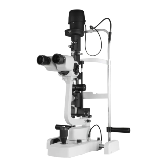
2. The slit lamp performs microscopic examination of the ocular fundus and posterior vitreous body (using hruby’s lens). 3. The slit lamp is designed for use ophthalmologists and optometrists. HUVITZ Co.,Ltd Customer Service Department 2013. 08. 16 3 / 72... - Page 4 Structure 1 HS-5000,7000 Illumination System Microscope Module Mechanical Body HUVITZ Co.,Ltd Customer Service Department 2013. 08. 16 4 / 72...
- Page 5 Structure 2 HS-5500,7500 Illumination System Microscope Module Mechanical Body HUVITZ Co.,Ltd Customer Service Department 2013. 08. 16 5 / 72...
- Page 6 ⑩ : Halogen lamp ① ⑪ : C mirror ② ⑫ ⑫ : OD’S Eyes ⑧ ④ ⑮ : Patient’s Eye ③ ⑮ ⑦ ⑮ ③ ⑤ ① ⑥ ⑫ ② HUVITZ Co.,Ltd Customer Service Department 2013. 08. 16 6 / 72...
-
Page 7: Illumination System
Illumination System HS-5000,7000 •1 Light source Halogen lamp (12V 30W) ① or LED •2 Slit length 0.3 ~ 12mm ② •6 Slit width 0 ~ 12mm (continuous) ③ •5 Slit projection ④ Aperture diaphragm 0.3 / 1 / 3 / 5 / 9 / 12mm ⑤... - Page 8 (green) Slit rotation 0 ~ 180˚ (continuous) ⑤ Horizontal tilting Slit movement ⑥ (left & right) Vertical tilting Angle change for slit ⑦ Diffuser Diffusing the light ⑧ HUVITZ Co.,Ltd Customer Service Department 2013. 08. 16 8 / 72...
- Page 9 Neutral Density filter (ND) is to reduces the amount of light. ③ Heat absorption (IR) filter is mainly used in lighting systems to absorb ④ the heat from a light source. HUVITZ Co.,Ltd Customer Service Department 2013. 08. 16 9 / 72...
- Page 10 Illumination System – Filter 2 Yellow Filter Yellow filter The Yellow filter fits RGP lenses with fluorescein dye After installation, check whether Yellow filter is removed or not. HUVITZ Co.,Ltd Customer Service Department 2013. 08. 16 10 / 72...
-
Page 11: Microscope
55 ~ 80mm ④ Filter yellow ⑤ Magnification 5 positions rotating drum ⑥ Total magnification & real field of view ⑦ 6x (38.5mm) 10x (22.2mm) 16x (15.2mm) 25x (10.5mm) 40x (6.7mm) HUVITZ Co.,Ltd Customer Service Department 2013. 08. 16 11 / 72... - Page 12 Part Name 1 •6 HUVITZ Co.,Ltd Customer Service Department 2013. 08. 16 12 / 72...
- Page 13 58. Luminosity selector connector (Connecting to the SMPS) 24. Knurled knob to lift the bulb holder 59. Head rest module 25. Ring for the vertical setting of the chin-rest 60. LED Lamp (Option) HUVITZ Co.,Ltd Customer Service Department 2013. 08. 16 13 / 72...
- Page 14 Installation TABLE TABLE MODULE (HS-5000) CIT-5000 (Made by HUVITZ) or your country’s model HUVITZ Co.,Ltd Customer Service Department 2013. 08. 16 14 / 72...
- Page 15 Installation HS-5000,7000 Stopper shaft 1. Table Ass’y 2. Main Body Ass’y 3. Microscope Ass’y 4. Illumination Ass’y 5. Rotation Guide Bolt 6. Wheel protection Cases 7. Head rest module 8. Screw M3 9. Bolt M6 10. Stopper shaft Rotation Guide Bolt HUVITZ Co.,Ltd...
- Page 16 Installation HS-5500,7500 1. Table Ass’y 2. Main Body Ass’y 3. Microscope Ass’y 4. Illumination Ass’y 5. Head rest module 6. Screw M3 7. Bolt M6 HUVITZ Co.,Ltd Customer Service Department 2013. 08. 16 16 / 72...
- Page 17 Be careful, you have to assemble the Microscope until you reach end of the stopper. STOPPER Using the test bar, check whether focus is aligned or not. (Try to move entire Microscope until the figure(sight) become clear) HUVITZ Co.,Ltd Customer Service Department 2013. 08. 16 17 / 72...
- Page 18 Installation CABLE Be careful, you have to connect the connector to the cable. HUVITZ Co.,Ltd Customer Service Department 2013. 08. 16 18 / 72...
- Page 19 (4) FireWire IEEE 1394 cable or (5) Software CD (6) Light sensor plate (7) Light sensor PCB (1394 or USB) (8) Scatter (Diffuser) (9) Auxiliary light cable supporter (10) Auxiliary light Module HUVITZ Co.,Ltd Customer Service Department 2013. 08. 16 19 / 72...
- Page 20 Installation HS-5000/7000 (1) ※ Notice : In case of equipped camera, you can skip the slide (1) ~ (10) 1. Remove the cover by loosening 2. Remove the old camera cables. the screws. HUVITZ Co.,Ltd Customer Service Department 2013. 08. 16...
- Page 21 Installation HS-5000/7000 (2) 3. Drill a hole by using 9mm drill. 4. Connect the USB camera connector. (only for HS-7000,7500) Check contact this bump with hole HUVITZ Co.,Ltd Customer Service Department 2013. 08. 16 21 / 72...
- Page 22 Installation HS-5000/7000 (3) 5. Assemble the camera board. 6. You have to connect 4-pin USB cable to COM3 2-pin cable to COM4 when you connect the board and cable. If the cables are twisted, it doesn’t work. HUVITZ Co.,Ltd Customer Service Department 2013.
- Page 23 Installation HS-5000/7000 (4) 7. Assemble the cover. 8. Attach the light sensor plate on the table. HUVITZ Co.,Ltd Customer Service Department 2013. 08. 16 23 / 72...
- Page 24 Installation HS-5000/7000 (5) 9. Loosen the screws on the side 10. Use the 2.5mm hexagonal wrench and separate the cover. for separation. HUVITZ Co.,Ltd Customer Service Department 2013. 08. 16 24 / 72...
- Page 25 Installation HS-5000/7000 (6) <Separating basic cover> HUVITZ Co.,Ltd Customer Service Department 2013. 08. 16 25 / 72...
- Page 26 Installation HS-5000/7000 (7) <Separating basic cover> HUVITZ Co.,Ltd Customer Service Department 2013. 08. 16 26 / 72...
- Page 27 Installation HS-5000/7000 (8) <Assembling the auxiliary light ass’y> 11. Mount the auxiliary light 12. Install the LED and PCB illumination module. HUVITZ Co.,Ltd Customer Service Department 2013. 08. 16 27 / 72...
- Page 28 Installation HS-5000/7000 (9) <Assembling the auxiliary light ass’y> 13. Tighten the screw on the upper side. 14. Insert the cover by turning. HUVITZ Co.,Ltd Customer Service Department 2013. 08. 16 28 / 72...
- Page 29 Installation HS-5000/7000 (10) <Completion auxiliary illumination module> HUVITZ Co.,Ltd Customer Service Department 2013. 08. 16 29 / 72...
- Page 30 Installation HS-5000/7000 (11) 15. Assembly the auxiliary illumination module with support fixture. HUVITZ Co.,Ltd Customer Service Department 2013. 08. 16 30 / 72...
- Page 31 Installation HS-5000/7000 (12) 16. Assemble the auxiliary light cable. 17. Assemble the scatter. 18. Separate microscope binocular. HUVITZ Co.,Ltd Customer Service Department 2013. 08. 16 31 / 72...
- Page 32 Installation HS-5000/7000 (13) DSLR Adapter HIS-5000U Camera 19. After attaching a camera ass’y, assembly the microscope again. HUVITZ Co.,Ltd Customer Service Department 2013. 08. 16 32 / 72...
- Page 33 Installation HS-5000/7000 (14) HIS-5000U Camera DSLR Adapter 20. Connect camera communication and USB cable in camera ass’y. HUVITZ Co.,Ltd Customer Service Department 2013. 08. 16 33 / 72...
- Page 34 Installation HS-5000/7000 (15) 21. Connect camera communication cable 22. Fix cables in the holder, so it doesn’t in the base. make to be affected in operation. HUVITZ Co.,Ltd Customer Service Department 2013. 08. 16 34 / 72...
- Page 35 Installation HS-5000/7000 (16) 23. Turn on and operate it. HUVITZ Co.,Ltd Customer Service Department 2013. 08. 16 35 / 72...
- Page 36 ※ Notice : In case of equipped camera, you can skip the slide (1) ~ (10) 1. Remove the cover by loosening 2. Remove the old camera cables. the screws. HUVITZ Co.,Ltd Customer Service Department 2013. 08. 16 36 / 72...
- Page 37 Installation HS-5500/7500 (2) 3. Drill a hole by using 9mm drill. 4. Connect the USB camera connector. (only for HS-7000,7500) Check contact this bump with hole HUVITZ Co.,Ltd Customer Service Department 2013. 08. 16 37 / 72...
- Page 38 6. You have to connect 4-pin USB cable to COM3 2-pin cable to COM4 when you connect the board and cable. If the cables are twisted, it doesn’t work. HUVITZ Co.,Ltd Customer Service Department 2013. 08. 16 38 / 72...
- Page 39 Installation HS-5500/7500 (4) 7. Attach the light sensor plate on the table. 8. Combine the scatter. HUVITZ Co.,Ltd Customer Service Department 2013. 08. 16 39 / 72...
- Page 40 Installation HS-5500/7500 (5) 10. Connect the cable of auxiliary 9. Connect the auxiliary illumination module. illumination module to SMPS. HUVITZ Co.,Ltd Customer Service Department 2013. 08. 16 40 / 72...
- Page 41 Installation HS-5500/7500 (6) DSLR Adapter HIS-5000U Camera 11. After attaching a camera ass’y, assembly the microscope again. HUVITZ Co.,Ltd Customer Service Department 2013. 08. 16 41 / 72...
- Page 42 Installation HS-5500/7500 (7) HIS-5000U Camera DSLR Adapter 12. Connect camera communication and USB cable in camera ass’y. HUVITZ Co.,Ltd Customer Service Department 2013. 08. 16 42 / 72...
- Page 43 Installation HS-5500/7500 (8) 13. Connect camera communication cable 14. Fix cables in the holder, so it doesn’t in the base. make to be affected in operation. HUVITZ Co.,Ltd Customer Service Department 2013. 08. 16 43 / 72...
- Page 44 Installation HS-5500/7500 (9) 15. Turn on and operate it. HUVITZ Co.,Ltd Customer Service Department 2013. 08. 16 44 / 72...
- Page 45 With watching the video of the camera to focus on the target ⊙ HIS-5000U CAMERA Loosen the lock using a 1.3mm hex wrench and focus on the target to using a one-party drivers. HUVITZ Co.,Ltd Customer Service Department 2013. 08. 16 45 / 72...
- Page 46 1. Using a 1.5mm hex wrench to loosen the three 2. Use a coin to turn left and right the bolt and focus by turning the ring back and forth. ring, then you can switch the view. HUVITZ Co.,Ltd Customer Service Department 2013. 08. 16 46 / 72...
- Page 47 Installation LED #1 <Install the LED lamp on HS-5000,7000> 1. Separate existing halogen lamp cover by loosening screws on the side. HUVITZ Co.,Ltd Customer Service Department 2013. 08. 16 47 / 72...
- Page 48 Installation LED #2 <Install the LED lamp on HS-5000,7000> 2. Separate halogen lamp module as above the picture. HUVITZ Co.,Ltd Customer Service Department 2013. 08. 16 48 / 72...
- Page 49 Installation LED #3 <Install the LED lamp on HS-5000,7000> 3. After affixing LED lamp module 4. Connect the connector and as above the picture, tighten it by light-fiber as above the picture. using 2.5mm hex wrench. HUVITZ Co.,Ltd Customer Service Department 2013.
- Page 50 Installation LED #4 <Install the LED lamp on HS-5000,7000> 5. Replace the SMPS and drawer. 6. Connect power and cable again. HUVITZ Co.,Ltd Customer Service Department 2013. 08. 16 50 / 72...
- Page 51 <Install the LED lamp on HS-5500,7500> 1. After disassembling screw cover and 2. Separate fixed bracket of halogen knob, loosen the screws on the side lamp as above the picture. for separating cover. HUVITZ Co.,Ltd Customer Service Department 2013. 08. 16 51 / 72...
- Page 52 Installation LED #2 <Install the LED lamp on HS-5500,7500> 3. After separating the connecter, using 2mm string or nipper to cut as above the picture. HUVITZ Co.,Ltd Customer Service Department 2013. 08. 16 52 / 72...
- Page 53 Installation LED #3 <Install the LED lamp on HS-5500,7500> 5. Assemble the LED bracket and tighten 4. Connect the LED Connecter the screws on the middle of hole. HUVITZ Co.,Ltd Customer Service Department 2013. 08. 16 53 / 72...
- Page 54 Installation LED #4 <Install the LED lamp on HS-5500,7500> 6. Connect the cable to cover. 7. Replace the SMPS and drawer. HUVITZ Co.,Ltd Customer Service Department 2013. 08. 16 54 / 72...
- Page 55 NEW SMPS Installation for reference What is the difference between NEW and Old ? □ Setting Switch! Old SMPS New SMPS HUVITZ Co.,Ltd Customer Service Department 2013. 08. 16 55 / 72...
- Page 56 (HS-5000, HS-5500, HS-7000, HS-7500) 4 3 2 1 1. Connect main light connector to CON4(HALOGEN) 2. Adjust the switch as above the picture. * Only for HS-5000, HS-5500, HS-7000, HS-7500 HUVITZ Co.,Ltd Customer Service Department 2013. 08. 16 56 / 72...
- Page 57 □ In case of using a main light, LED LAMP(5000/7000/5500/7500) 4 3 2 1 1. Connect main light connector to CON10 (MAIN_LED) 2. Adjust the switch as above the picture. * Only for HS-5000, HS-7000, HS-5500, HS-7500 HUVITZ Co.,Ltd Customer Service Department 2013. 08. 16 57 / 72...
- Page 58 □ In case of using a main light, LED LAMP(5000/7000) + LED auxiliary light(5000/7000) 4 3 2 1 1. Connect main light connector to CON10 (MAIN_LED) 2. Adjust the switch as above the picture. * Only for HS-5000, HS-7000 HUVITZ Co.,Ltd Customer Service Department 2013. 08. 16 58 / 72...
- Page 59 □ In case of reducing 75% of the halogen light (HS-6300) 4 3 2 1 1. Connect main light connector to CON10 (MAIN_LED) 2. Adjust the switch as above the picture. * Only for HS-6300 HUVITZ Co.,Ltd Customer Service Department 2013. 08. 16 59 / 72...
-
Page 60: Installation Of Joystick Driver
COM ports are displayed. In this case, open Device Manager, Ports(COM & LPT) to see. As follows: Silicon Labs CP210x USB to UART Bridge marked with a check to set the COM number. HUVITZ Co.,Ltd Customer Service Department 2013. 08. 16... - Page 61 OPTION □ STAND ALONE TABLE TOP – Useful to set unit table HUVITZ Co.,Ltd Customer Service Department 2013. 08. 16 61 / 72...
- Page 62 OPTION □ Size Calibration TOOL – You can measure distance, angle, dimension and diameter through the shot – If you want to know more, please refer to S/W manual. HUVITZ Co.,Ltd Customer Service Department 2013. 08. 16 62 / 72...
- Page 63 (never touch the KNOB bulb whit fingers) Fasten the bulb with the knob BULB STOPPER Warning : Don’t Touch the Lamp House, During Operation. It’s Heating up. HUVITZ Co.,Ltd Customer Service Department 2013. 08. 16 63 / 72...
- Page 64 Repair - Fuse 1. Before doing anything else, disconnect the plug from the main supply socket. 2. Remove the fuses housing, Replace the fuses. FUSE FUSE HOUSING HUVITZ Co.,Ltd Customer Service Department 2013. 08. 16 64 / 72...
- Page 65 5. After fix the clear point, compare the camera image and real image. And do step 2 to 5 until find the clear point. 1) Test bar 2) Eye Piece 3) The M MAIN FIXING SHAFT KNOB HUVITZ Co.,Ltd Customer Service Department 2013. 08. 16 65 / 72...
- Page 66 How to connect extension cables HUVITZ Co.,Ltd Customer Service Department 2013. 08. 16 66 / 72...
- Page 67 How to connect extension cables VR EXT cable(600mm) POWER EXT cable(5M) HUVITZ Co.,Ltd Customer Service Department 2013. 08. 16 67 / 72...
-
Page 68: Trouble Shooting
Check the installation of joystick driver properly. - Check the setup of joystick serial port on computer properly. (refer to S/W manual) - Generally, the joystick port is listed at the bottom of the list on software. HUVITZ Co.,Ltd Customer Service Department 2013. 08. 16... - Page 69 ▶ Move the Slit lamp to the end of the left ▶ Move the Slit lamp to the end of the right ※ Notice It is possible that you execute location correction function if you put the power to the PCB ASSY(Z1_USB_JOYSTICK) It is irrelevant to HIS program. HUVITZ Co.,Ltd Customer Service Department 2013. 08. 16 69 / 72...
- Page 70 So you should use USB cable one more if your customer use the latest IMAC(2013) that have USB 3.0 ports. < Existing Y cable > <USB cable for the latest IMAC(2013)> HUVITZ Co.,Ltd Customer Service Department 2013. 08. 16 70 / 72...
- Page 71 Please connect Slit Lamp Body with PC using Y cable and connect HIS Camera with PC using USB cable. < Refer to the photos 2), 3) > Slit Lamp Body HIS Camera HUVITZ Co.,Ltd Customer Service Department 2013. 08. 16 71 / 72...
- Page 72 “Re:define, Re+create” We are making a great company together!! - Thanks - HUVITZ Co.,Ltd Customer Service Department 2013. 08. 16 72 / 72...
Need help?
Do you have a question about the HS-5000 and is the answer not in the manual?
Questions and answers