Table of Contents
Advertisement
Quick Links
Advertisement
Table of Contents

Related Manuals for Huvitz SMART BLOCKER HBK-410


Summary of Contents for Huvitz SMART BLOCKER HBK-410
- Page 1 SMART BLOCKER HBK-410 USER MANUAL...
- Page 2 HUVITZ reserves the right to make changes in its products or product specifications at any time and without prior notice, and is not required to update this documentation to reflect such changes.
-
Page 3: Table Of Contents
HBK-410 CONTENT 1. Introduction ........................6 1.1. Main Features ............................6 1.2. System Configuration .......................... 7 1.3. Classification ............................7 2. Safety Information ......................8 2.1. Introduction ............................8 2.2. Safety Symbols ............................ 9 2.3. Environmental Considerations ......................10 2.4. Safety Precautions .......................... - Page 4 5.5. Digital Pattern ............................ 51 5.5.1. Enlargement/Reduction ..................... 52 5.5.2. Near Vision Area Enlargement/Reduction ................ 53 5.5.3. Rotation ..........................54 5.5.4. Partial Modification ......................56 5.5.5. Toggle R/L Sync ......................... 58 5.5.6. Reset ..........................59 5.5.7. Exit ............................. 59 5.6. Hole Editor ............................
- Page 5 HBK-410 7.9. Maintenance Tips ..........................114 7.9.1. Fuse Replacement......................114 7.9.2. Regular maintenance ...................... 114 7.9.3. Cleaning ........................... 114 8. Troubleshooting Guide ....................115 9. Specifications and Accessories..................116 9.1. Standard Accessories ........................116 9.2. Specifications........................... 116 9.3. Drawings of System......................... 117 10.
-
Page 6: Introduction
Introduction This product is the device for blocking, which means mounting the adapter on the lens. The operator adjusts the position of the lens using camera image and information for edging and performs the blocking manually. Main Features 1.1. • This product provides a different guide for blocking, depending on the type of lens such as a lens marked by lens-meter, bifocal lens and progressive lens. -
Page 7: System Configuration
HBK-410 System Configuration 1.2. • Interface the Smart Blocker with frame reader and edger. Frame Reader Smart Blocker Edger Classification 1.3. This device complies with Part 15 of the FCC Rules. Operation is subject to the following two conditions: (1) this device may not cause harmful interference, and (2) this device must accept any interference received, including interference that may cause undesired operation. -
Page 8: Safety Information
Safety Information Introduction 2.1. Safety is everyone’s responsibility. The safe use of this machine is largely dependent upon the installers, users, operators, and managers. It is prerequisite to read and understand these specifications before installing, using, cleaning, fixing or revising. Fully understanding the whole instructions must be the first priority. -
Page 9: Safety Symbols
HBK-410 Safety Symbols 2.2. The International Electrotechnical Commission (IEC) has established a set of symbols, which are listed below. This applies only to the instrument that has the certification symbol printed explicitly on the product label or sticker. I and O on power switch represent ON and OFF respectively. (I et O sur l'interrupteur d'alimentation représentent ON et OFF respectivement.) This symbol identifies caution, risk of danger. -
Page 10: Environmental Considerations
appareil, veuillez contacter votre mairie, le service d'élimination des déchets ou le magasin où vous avez acheté le produit.) Alternating Current (Courant alternative) Environmental Considerations 2.3. Avoid the following environments for operation or storage: Where the machine is exposed to water vapor. Don’t operate the machine with wet hands Indoor use only. - Page 11 Be cautious so that things like dust and metal do not fall inside the machine. Don’t disassemble or open the product. HUVITZ does not take responsibility for the possible problems Be careful not to block the fan of the machine.
-
Page 12: Safety Precautions
8. This machine must be connected with the accessories supplied by HUVITZ. If you are to use other accessories, their safety or usability must be checked and proved by their manufacturers or HUVITZ. - Page 13 HBK-410 that the connector (plug) is appropriate for the receptacle (socket). If you caused any damage to a cable connector(s) or receptacle(s), let the damage(s) be repaired by an authorized service technician. 12. Please do not pull on any cable. Always grab the plug when disconnecting cables. 13.
- Page 14 CAUTION When moving the machine, first fix the stage and check whether the power supply is off. • Then, should lift the bottom of the product with both hands. When setting down the machine, make sure not to be interfered with the obstacles. Set down •...
-
Page 15: System Overview
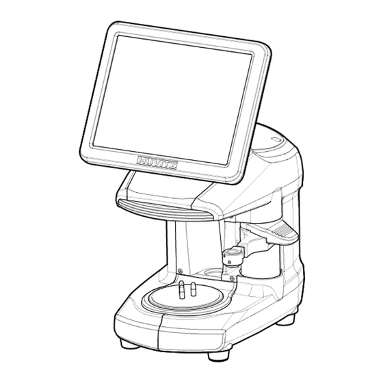
HBK-410 System Overview Front View 3.1. Display (Touch Screen) Blocking Arm Lens Supporter Reflector Rear View 3.2. SD card slot Power Switch Interface Terminal • EDGER 1 • EDGER 2 • Barcode Reader • Tracer Main Power Input and Fuse... -
Page 16: Standard Accessory
Standard Accessory 3.3. Lens Supporter Lens Supporter for Frame Change and Digital Scanning Touch Pen NOTE Please use genuine lens adaptor tape (LEAP-III). Otherwise, the lens axis may move. • • We do not provide a sticker for Super Hydrophobic Lens, but you should use qualified ones, or the lens axis may move. -
Page 17: Installation
HBK-410 Installation Installation Procedure 4.1. ① Remove the shock-absorbing materials from the packing box and take out the smart blocker carefully. ② Remove the shock-absorbing materials from the blocking arm. ③ Plug the Power Cable into the socket at the rear side of the product and turn on the power. ④... - Page 18 ① Connect a 9-pin serial cable to the EDGER 1 port of the HFR-8000X and the TRACER port of the HBK-410. ② Connect a 9-pin serial cable to the EDGER 1 port of the HBK-410 and the TRACER/BLOCKER port of the HPE-8000X. ③...
-
Page 19: Smart Blocker User Interface
HBK-410 Smart Blocker User Interface Main Screen 5.1. Side Button Frame Information Job Management Layout Option Lens Edging Option Function Button Function Button Information 5.1.1. Side Button ① Press the R button to select right side. ② Press the L button to select left side. - Page 20 NOTE Each side of frame shape is exchanged by pressing the R button for a while. • • Left and Right sides are exchanged. The other job options remain unchanged. The function of exchange R/L is useful when you selected wrong side while reading demo lens •...
- Page 21 Some OMA files may not be fully compatible with our system. So please note that it may not be • able to process normally. OMA import function is available after being activated in the menu (Ask to the service • technician of HUVITZ or the technician authorized by HUVITZ).
-
Page 22: Job Management
5.1.2. Job Management ① New : Clear current job screen and wait new job. ② Job Number : Display current job number (Press the button to change job number). ③ Job Manager : Press the job manager button to load a new job or move on to another job. NOTE Virtual Keyboard •... - Page 23 HBK-410 NOTE Following additional functions are available by pressing ‘Job Management’ button for a while. • You can save current job on SD card by pressing ‘Job Number’ for a while. • • If you append file extension such as “.oma” or “.dxf” at the end of “Job Number”, you can export a job to OMA file or CAD file in the “oma/export”...
-
Page 24: Frame Information
5.1.3. Frame Information ① Frame Curve (In case of pattern, input demo lens curve) ② Circumference ③ Minimum Lens Diameter ④ Width/Height 5.1.4. Layout Option ① Binocular PD: Input prescribed binocular PD value. ② Monocular PD : Input PD values for each side (L/R). ③... - Page 25 HBK-410 NOTE When you input Binocular PD value, Monocular PD values for each side are automatically • calculated and vice versa. When you input Bridge Size value, FPD value is automatically calculated and vice versa. • In case of Two Eye Tracing, the value of FPD will be automatically transmitted and displayed. •...
- Page 26 NOTE In layout information, PD, OH, Bridge Size, FPD are mandatory value. The color of input box of • these values is changed when you input value. • The box which is not changed from default value is colored yellow. It changes into white when you input value.
- Page 27 HBK-410 NOTE Layout information, edging information and lens information can be modified in advance before • or while tracing the frame information by frame reader or digital scan. The modified information will be applied to the new job from the frame reader or digital scan. NOTE Numeric Keypad •...
-
Page 28: Edging Option
5.1.5. Edging Option ① Edging Type Bevel Flat Grooving Mini Bevel Asymmetric Bevel Semi-U Bevel NOTE Available edging types can vary by wheel types of the edger. • Normal Type (RPG, RPW) Asymmetric Type (RPA, RPGA) Step Bevel edging type is available when the edger type setting is HPE-8000X in the •... - Page 29 HBK-410 NOTE You can input additional parameters according to the selected edging type. • Grooving • ① Groove Depth ② Groove Width Mini Bevel • ① Bevel Height Asymmetric Bevel • ① Front Height ② Rear Height • Semi-U Bevel ①...
- Page 30 NOTE After you’ve selected grooving as the edging type, you can select partial grooving by pressing • ‘Edging type’ button for a while. There are four ways of partial grooving. • Partial Grooving Hybrid Grooving Partial Bevel Dual Grooving (Flat+Grooving) (Bevel+Grooving) (Bevel + Flat) Relevant icon is displayed at edging type when partial grooving is selected.
- Page 31 HBK-410 ② Bevel/Groove Position Front % Front mm Rear mm Base Curve Auto Manual ③ Size Adjustment (-2.0 ~ 2.0mm) ④ Polishing Polishing Off Polishing On High Polishing ⑤ Front Safety Beveling Safety Beveling Off Safety Beveling On ⑥ Rear Safety Beveling Safety Beveling Off Safety Beveling Small Safety Beveling Large...
- Page 32 NOTE Polishing / Safety Beveling touch screen area • ① Polishing On/Off ② Front Safety Beveling On / Off ③ Rear Safety Beveling Off / Small / Large • When you selected ‘Asymmetric Bevel’ or ‘Semi-U Bevel’, rear safety beveling is not available. Safety Beveling option is disabled in Hybrid Grooving (Bevel+Grooving) and Partial Bevel •...
-
Page 33: Lens Information
HBK-410 5.1.6. Lens Information ① Lens Type 3-dot marked Bi-focal Bi-focal Bi-focal Progressive (Flat) (Round) (Curved) ② Blocking Mode Optical Center - Set blocking location to the optical center. Boxing Center - Set blocking location to the box center. (Frame Center) ③... - Page 34 NOTE You can change the guideline according to the lens type. • Press the guideline value box area and enter the value to change. • Normal lens • ① 3-dot length Bi-focal lens • ① Near vision area diameter Progressive lens •...
- Page 35 HBK-410 NOTE Boxing Center is useful for the following cases. • When PD is in eccentric position When frame is horizontally wide Super Hydrophobic Lens or Ultra Hi-Index Lens When you choose the options for Bi-Focal, Near Vision Shape will be displayed on the screen. •...
- Page 36 Min Max (-) Lens (+) Lens [Base curve mode] In the base curve mode, base curves of (+) lenses and (-) lenses exist the opposite side. In • this mode, the bevel or grooving line always passes the mid of the thinnest parts, one of which is located at the midst zone of (-) lens and the other is located at the edged zone of (+) lens.
-
Page 37: Function Button
HBK-410 5.1.7. Function Button ① Expert Job Editor ② Menu ③ Digital Designer (Digital Pattern + Hole Editor) ④ Digital Scan ⑤ Blocking NOTE The expert user can work more quickly by using ‘Expert Job Editor’. -
Page 38: Blocking Screen
Blocking Screen 5.2. Press button on the main screen to enter blocking screen. Blocking Mode Exit Layout Information Lens Type Brightness Control Send Zoom / Rotation... -
Page 39: Layout Information
HBK-410 5.2.1. Layout Information ① Monocular PD ② OH (Optical Height) ③ OH Type (ΔY, Box Height, Mix Height) ④ Blocking Mode NOTE You can enter PD/OH value directly or fine tune with the +/- buttons. ① Monocular PD ② OH (Optical Height) ③... -
Page 40: Tool Button
NOTE On the right side of the screen you can change the lens guideline and display the grid. ① Guideline ② Grid On/Off ③ Grid space 5.2.3. Tool Button ① Brightness Control : Low ② Brightness Control : High ③ Live Image : Normal / Zoom ④... - Page 41 HBK-410 NOTE When the lens type is the progressive lens, you can use laser mark for blocking. • • When the lens type is changed to the progressive lens, the buttons are displayed in the bottom right ( decrease contrast increase contrast).
-
Page 42: Digital Scan
Digital Scan 5.3. This is for recognizing the frame/holes/slot/notch by scanning demo-lens. To use digital scan, click the button on the bottom right of the main screen. ① Select right side. ② Select left side. ③ Adjust LED brightness manually. ④... - Page 43 HBK-410 How to use Digital Scan ① Change to Digital Scan lens plate. ② Mark 3-dots or draw straight line for axis on the demo-lens. Then, place the lens on the plate. ③ Select side. ④ Press the start button for Digital Scan. ⑤...
- Page 44 CAUTION The Digital Scan grab the frame shape from the demo lens with high resolution and accuracy. • So if the demo lens is different in size or shape from the frame, it’ll be reflected in the grabbed frame shape either and the result lens will not make a good fitting in the frame. It’s recommended to check and follow the instruction in the below for better fitting.
-
Page 45: Job Manager
HBK-410 Job Manager 5.4. Job selection tab Exit Job list Function button... -
Page 46: Job Selection Tab
5.4.1. Job selection tab ① Waiting Job : Newly received Job data from the frame reader or Digital Scan. ② Working Job : Blocking job or Editing job ③ Completed Job : Blocked Job ④ Saved Job List : Job data saved in SD card. ⑤... -
Page 47: Waiting Job
HBK-410 5.4.3. Waiting Job ① Job Number: Displays the Job Number. ② Type: Displays the Edging Type with icon. ③ Reading: Displays the Tracing State with icon. ④ Frame Type: Displays the Frame Type. ⑤ FPD: Displays the FPD value. ⑥... -
Page 48: Completed Job
5.4.5. Completed Job ① Time: Displays the job finish time. NOTE You can check current processing state with the following icons. • ① Waiting ② One side blocking completed ③ Both sides blocking completed... -
Page 49: Job Search
HBK-410 5.4.6. Job Search You can search for a job on the job list. ① Start ‘Job Search Mode’ by pressing the search button. ② Enter the job number you want with the virtual keyboard. ③ Check the list. Enter Job Number Search Button... - Page 50 You can search with only few letters, not the whole words. For example, you can search the • Job Number ‘HUVITZ_123’ only with ‘HUVITZ’ or ‘123’. You can look at the other research results with ‘Next’ and ‘Prev’ button. •...
-
Page 51: Digital Pattern
HBK-410 Digital Pattern 5.5. The “Digital Pattern” modifies the lens shape in left/right, top/bottom as well as rotation and optimizes the fitting for Rimless and Semi-Rimless. To use Digital Pattern, press button on the bottom right of the main screen and then select the Digital Pattern tab at top left of the screen. Zoom Exit Touch Area... -
Page 52: Enlargement/Reduction
5.5.1. Enlargement/Reduction Lens shape can be modified both horizontally and vertically. Touch Interface To modify lens shape, make use of the 8 touch points around the lens shape. ① Horizontal + Vertical ② Horizontal ③ Vertical [Vertical] [Horizontal + Vertical] [Horizontal] Value Input You can modify the lens shape by entering the... -
Page 53: Near Vision Area Enlargement/Reduction
HBK-410 5.5.2. Near Vision Area Enlargement/Reduction Lens shape can be changed in four directions (Bottom - Near Vision Area, Top, Left, Right). Touch Interface To modify lens shape, make use of 4 touch points around the lens shape. ① Left or Right ②... -
Page 54: Rotation
Value Input You can modify the lens shape by entering the values directly in the Input Area. ① Left ② Right ③ Near Vision Area (Bottom) ④ After selecting the item to change, enter the value using the numeric keypad. 5.5.3. - Page 55 HBK-410 [Clockwise] [Counterclockwise] Value Input You can modify the lens shape by entering value directly in the Input Area. ① Width ② Height ③ Angle (Clockwise, 0 ~ 360) Function of ① and ② are same with that of Enlargement/ Reduction mode. After selecting the item to change, enter the value using the numeric keypad.
-
Page 56: Partial Modification
5.5.4. Partial Modification Lens shape can be modified partially. Touch Interface Change modification area by touching any point on lens shape. The point becomes the center of the modification area. To adjust modification range, touch and drag one of 2 touch points around the selected lens shape (blue). - Page 57 HBK-410 Lens Shape Modification You can modify the lens shape with Input button. ① Edit mode (Curved or Linear) ② Edit Position Change ③ Position change (counter clockwise, clockwise) ④ Range change (enlargement, reduction) ⑤ Wide Partial Modification (concave, convex) ⑥...
-
Page 58: Toggle R/L Sync
• The Edit position can be switched to the center or the other end point quickly by holding edit position change button ( 5.5.5. Toggle R/L Sync Function for R/L Sync. [R/L Sync On] [R/L Sync Off] NOTE “Copy” button ( ) is available when R/L sync option is turned off. -
Page 59: Reset
HBK-410 5.5.6. Reset Recover original lens shape. 5.5.7. Exit Quit digital pattern and return to the main screen. To apply modified lens shape, Press the “Apply” button on the confirm dialog box. NOTE • You can modify half-framed lens or rimless lens conveniently by using the digital pattern. The digital pattern is useful for the bi-focal lens or the progressive. -
Page 60: Hole Editor
Hole Editor 5.6. This screen is for the edition of hole position for drilling. To use the hole editor, click the button( on the main screen right below, and then select the hole editor button in the upper left. Working Area Preview Top of hole editor List of Hole/Slot... -
Page 61: Upper Side Of Hole Editor
HBK-410 5.6.1. Upper Side of Hole Editor ① Hole Editor : Starts the hole editor. If the button is green, hole editor is now available. ② Digital Pattern : Starts the digital pattern. ③ Job Number : Displays the job number of currently working job. You can modify the number by touching here. ④... - Page 62 NOTE Elements required for drilling are displayed on working area. The figure below describes each element. Frame Center Hole Horz. Coordinate Notch or Slot Vert. Coordinate Undrillable area...
-
Page 63: Preview
HBK-410 5.6.3. Preview ① Select Right/Left: You can change the selection of the left/right. When the camera mode is set to ‘still image’, you cannot change the side (L/R) because the frame is not identical with the image. You must change the camera mode from still image to live image first to change the side selection. -
Page 64: Function Buttons
5.6.4. Function Buttons ① Hole / Slot Detection: You can use this button when you want to add holes/slots after the frame reader has read a demo lens. If the camera is on live image mode, you can start detection by pressing this button. If the camera is on still image mode, you can change the mode to live image and start detection by pressing this button. - Page 65 HBK-410 NOTE Demo lens for switching camera mode and detection of hole/slot must have an axis indicator. • There are 2 ways to indicate the axis. ① To draw a straight line along the axis. ② To mark the 3 dots along the axis. If there is no axis indicator, the horizontal line on the camera image is regarded as the axis of demo lens.
- Page 66 The details of how to move the hole / slot by moving type are like below. • : This provides the function of parallel movement. The movement of hole / slot is like below. [Hole] [Slot] : (Slot only) This provides the function to move the start position of a slot. : (Slot only) This provides the function to move the end position of a slot.
- Page 67 HBK-410 : (Slot only) This provides the function to rotate a slot. : (Slot only) This provides the function to change the length of a slot. : (Slot only) This provides the function to change a slot to a notch and to move the notch.
- Page 68 NOTE On the preset, there are three functions. • ① Save the hole / slot data: You can save the hole / slot data of the current job to the SD card. a. List of hole / slot data : This displays a list of hole / slot data in the SD card.
- Page 69 HBK-410 ③ Set preset: You can set the 8 preset buttons. ( ). You can put hole/slot saved in SD card to each button. These 8 presets can be used to add the favorite set of the hole / slot data to the current job, easily. a.
- Page 70 NOTE The mirroring is a function that copies the selected hole / slot to the opposite side. The distance between mirrored hole/slot and the frame edge is same with the distance between original one and the frame edge. In case of slot, the distance between the start point of a side (closest point to the frame) and the frame must be identical with the distance between the end point of the other side (closest point to the frame) and the frame (The two points must be symmetric).
-
Page 71: List Of Hole/Slot
HBK-410 5.6.5. List of Hole/Slot It displays the hole / slot list of the current job. You can change the position of the hole / slot by pressing the coordinates displayed on the list. ① Select the hole / slot : You can select the holes / slots to make a group by pressing here. - Page 72 the length of a slot in X direction the slope of a slot ⑦ Change how to display the Y coordinate of a slot You can change the way Y coordinate of a slot is displayed ⑤ Based on the option by the length of a slot in Y direction the length of a slot ⑧...
- Page 73 HBK-410 NOTE Display options for X coordinate • Center of frame Frame edge Display options for Y coordinate • Center of frame Bottom of box...
-
Page 74: Property Of Hole/Slot
5.6.6. Property of Hole/Slot It displays the properties of the selected hole / slot. ① Group : If selected hole / slot belongs to a group, it displays the group id. If selectedn hole / slot does not belongs to a group, it displays with the ‘-’. -
Page 75: Job Editor
HBK-410 Job Editor 5.7. Job editor provides the whole edging options at once, so it is useful for the skillful users. 5.7.1. Layout Option PD (Binocular PD, R/L Monocular PD) Box Height ΔY Mix Height Bridge size (DBL) Frame curve Circumference Frame Tilting Angle Demo Lens Curve... -
Page 76: Edging Option
Frame Type Blocking mode Lens type Near vision area diameter 5.7.2. Edging option Edging type Lens material Bevel/Grooving position Size Polishing Safety mode Front safety beveling Rear safety beveling Step bevel NOTE The job editor options are applied to right/left both side concurrently. But if the options distinguish the two sides, those are applied only to the selected side. -
Page 77: Step Bevel Editor
HBK-410 Step Bevel Editor 5.8. Step bevel editor provides professional editing function for step bevel edging. The editor screen will be displayed when you select edging type to step bevel or press the editor button ( ) on the bottom of the main screen. -
Page 78: Step Bevel Processing Mode
5.8.1. Step Bevel Processing Mode You can select the step bevel processing mode by option buttons. Partial Step Bevel : Process user selected region (For half frame goggle) Full Step Bevel : Process whole region (For full frame goggle) 5.8.2. Partial Step Bevel Editing Area ①... - Page 79 HBK-410 NOTE In case of partial step bevel mode, you can enter depth value into three (top/left/right) • reference direction. (unit: mm) Use the step button( ) to fine-tune the depth value. (1 step = 0.05mm) • The fine-tune value of the data obtained by scanning is set to 0.0. It will be edited to a relative •...
- Page 80 NOTE Touch the lens shape area, then the editing position moves to the touched area. • • To see the shape in actual size, press the upper right icon. Touch Area [Actual measurement] [Auto – Shape resized to fit to the screen) •...
-
Page 81: Partial Step Bevel Option
HBK-410 5.8.3. Partial Step Bevel Option ① Angle of the start/end point ② Step bevel finishing mode (Auto/Safety) ③ Inclined cut mode on/off NOTE • Start point and end point are represented by the angle. And the angle starts with the 6 o’clock position from 0 degree in a clockwise direction. -
Page 82: Full Step Bevel Editing Area
5.8.4. Full Step Bevel Editing Area ① Side selection ② Current editing position (White rectangle) ③ Step bevel depth input ④ Edging impossible area NOTE When creating the step bevel data, there are two types ( ) of initial step bevel line •... - Page 83 HBK-410 [Following wheel processing shape] [Following final shape]...
-
Page 84: Full Step Bevel Option
5.8.5. Full Step Bevel Option ① Step bevel depth batch input ② Main wheel edging type (Flat / Bevel) ③ Inclined cut mode on/off NOTE In case of full step bevel mode, you can enter depth value into four (top/left/right/bottom) •... - Page 85 HBK-410 NOTE Editing area with fine tuning function activated • Editing scope value is represented by the angle and the scope can be changed by • increase/decrease buttons ( [ 30° scope] [60° scope] • Move editing position to target and confirm scope. Then modify step bevel shape by the modification( ) buttons.
- Page 86 The color of the step bevel shape can be changed according to the editing result and the meaning • of the color is as follows: ① Red : Step bevel shape invades edging impossible area or exceeds depth limit. In this situation, edging is impossible.
- Page 87 HBK-410 NOTE When there is red line in the editor, button will be shown in the right bottom and you can • edit manually using the edit button or modify the red line automatically by touching the button. After touching button, the red line and the button will be disappeared •...
-
Page 88: Preview
5.8.7. Preview ① Opposite side display ② Edging shape of opposite side ③ R/L sync on/off ④ Copy to opposite side NOTE Preview screen always shows opposite side data. • • When R/L sync is turned on, editing result will be applied to both side. Copy button ( ) is available when R/L sync option is turned off. -
Page 89: Current Position Information
HBK-410 5.8.8. Current Position Information It displays the information of current position. You can input additional information for step bevel shape. ① Move editing position counterclockwise ② Move editing position clockwise ③ Step bevel depth ④ Step bevel front width input ⑤... -
Page 90: Safety Beveling & Polishing Option
edging surface. Shape of step bevel can be selected according to the type of the frame and the lens to be • processed. Rear step bevel Front step bevel T-bevel (Both) In case of ‘Front step bevel’ and ‘T-Bevel (Both)’, you can adjust bevel position in the manual •... -
Page 91: Reset & Apply Button
HBK-410 5.8.10. Reset & Apply Button ① Reset Button – Cancel the changes and return to initial state ② Apply button – Apply changes and close the editor NOTE When you apply the changes if the result shape is not possible to edging or expected to be •... -
Page 92: Bevel Height Editor
Bevel Height Editor 5.9. Bevel height editor provides professional editing function for asymmetric/semi-u bevel. The editor screen will be displayed when you select edging type to asymmetric/semi-u or press the editor button ) on the bottom of the main screen. Preview Position Information Editing Area... -
Page 93: Editing Area
HBK-410 5.9.1. Editing Area ① Side selection ② Current editing position (White rectangle) ③ Bevel rear height input ④ Edging impossible area NOTE You can enter bevel rear height value into four (top/left/right/bottom) reference direction. • (unit: mm) Use the step button( ) to fine-tune the depth value. - Page 94 NOTE Touch the lens shape area, then the editing position moves to the touched area. • • To see the shape in actual size, press the upper right icon. Touch Area [Actual measurement] [Auto – Shape resized to fit to the screen) Angle guideline pops up when you touch the center of the shape.
-
Page 95: Preview
HBK-410 5.9.2. Preview ① Opposite side display ② Edging shape of opposite side ③ R/L sync on/off ④ Copy to opposite side NOTE • Preview screen always shows opposite side data. • When R/L sync is turned on, editing result will be applied to both side. Copy button ( ) is available when R/L sync option is turned off. -
Page 96: Current Position Information
5.9.3. Current Position Information It displays the information of current position. You can input additional information for bevel shape. ① Move editing position counterclockwise ② Move editing position clockwise ③ Bevel rear height ④ Asymmetric bevel front height input (Semi-U bevel front width input) NOTE Current position information shows lens processing position with the assumption that the lens •... -
Page 97: Edging Option
HBK-410 5.9.4. Edging Option ① Editing mode ② Bevel rear height batch input ③ Front safety beveling NOTE • Currently the editor supports only full region editing mode. With the batch input button you can enter all reference height values at a time. •... -
Page 98: Configuration
Configuration Press button on the bottom left of the Main screen. MENU Screen ① Preferences ② Software Version ③ Exit the menu screen NOTE Refer to ‘Chapter 7. System Maintenance’ for the other functions. • Please be careful not to suddenly turn off the power while using the device. •... -
Page 99: Preference
HBK-410 Preference 6.1. User Interface can be customized to the user’s preference. General Default settings for User Interface option. Language – Sets default language. • Beep – Turns on or off the beep sound. • • Sleep Mode – Inputs sleep mode waiting time. (minutes) •... - Page 100 NOTE Setting Screen • ① Tab Menu. ② List Box – Choose a list from existing options. ③ Radio Button – Choose only one of a predefined sets of options. ④ Input Box – Input value to be used by the program. ⑤...
- Page 101 HBK-410 Layout Default settings for Layout options. • Default Side – Select the default side for a new job. Automatic Switch Side – Set automatic side change after blocking. • Lens Type – Select the default lens type for a new job. •...
- Page 102 Edging Default settings for Edging options. Lens Material – Set the default lens material. • • (Opt) Step Bevel Lens Material - Set the default lens material for step bevel. Safety Mode – On or Off the safety mode. • Enable Glass Flat Edging –...
- Page 103 HBK-410 Hole Editor Default settings for Hole Editor options. • Use Hole Editor – Hole Editor On/Off. • Notify usability to user - Displays the hole editor enable message box. Hole Depth – Set default hole/slot depth value. • Hole Diameter – Set default hole/slot diameter value. •...
- Page 104 Digital Pattern Default settings for Digital Pattern options. • Digital Pattern Apply Method. Fix FPD – Calculates bridge size value based on FPD. Fix Bridge Size – Calculates FPD value based on bridge size. • Enable Background Camera Image...
- Page 105 HBK-410 Communication Port Default settings for communication options. • Barcode Reader - Use Barcode Reader port. Baud Rate - Set communication speed. Edger1 – Use Edger1 port. • Protocol – Set communication protocol. Baud Rate – Set communication speed. •...
-
Page 106: System Maintenance
System Maintenance Brightness Test & Calibration 7.1. You can diagnose the current brightness and calibrate it. -
Page 107: Save Image
HBK-410 Save Image 7.2. When the digital scan quality is low, you can save the image file to SD card and request improvement. Save Digital Scan image During digital scan, you can save digital scan image if you want. (SD card must be inserted in slot) ①... -
Page 108: Test Mode
Test Mode 7.3. You can check the sensor info of the Blocker and test the motor of the reflector. ① Z Axis Limit Switch Value ② Reflector BLDC Motor On/Off ③ Exit Test Mode... -
Page 109: Date & Time
HBK-410 Date & Time 7.4. You can change the system time. Please set the date and time first after you install this machine. ① Date selection calendar ② Year ③ Month ④ ⑤ Hour ⑥ Minute ⑦ Second ⑧ Apply modified data & time ⑨... -
Page 110: Touch Test
Touch Test 7.5. You can check the normal operation of the touch screen NOTE You can use the emergency touch screen test function if the touch test is not possible • ① Turn off the device and turn on the power switch while pressing the touch screen. ②... -
Page 111: Configuration Management
HBK-410 Configuration Management 7.6. You can backup or restore system configuration data. ① Backup to SD Card – Backup configuration data to SD card. ② Restore from SD Card – Restore configuration data from SD card ③ Factory Reset – Restore to factory default setting. NOTE Configuration Management function is available when SD card inserted. -
Page 112: Sw Upgrade
SW Upgrade 7.7. You can update to the latest software. ① GUI – Upgrade GUI software NOTE It is highly recommended to use latest software. • If you have multiple versions of SW in the SD card, you can select the version by pressing •... -
Page 113: Maintenance Code
HBK-410 Maintenance Code 7.8. Maintenance code is used for the engineer to diagnose the system. -
Page 114: Maintenance Tips
7.9.2. Regular maintenance It is recommended to keep the regular maintenance cycle in order to maintain the Edging Performance. Be sure to carry out the regular maintenance by the service technician of HUVITZ or the technician authorized by HUVITZ. 7.9.3. Cleaning ①... -
Page 115: Troubleshooting Guide
HBK-410 Troubleshooting Guide If problems occur, please review the following list and take remedial action as needed. If you cannot solve the problem after checking the entire list, please contact your authorized distributor or HUVITZ. Problem Cause Solution ① Adhesive strength has been ①... -
Page 116: Specifications And Accessories
Specifications and Accessories Standard Accessories 9.1. User’s Manual ··················································································································· 1 Lens Supporter ·················································································································· 1 Lens Supporter for Frame Change and Digital Scanning ···························································· 1 Touch Pen ························································································································ 1 Specifications 9.2. Imaging Camera CMOS B/W 1.3M Blocking Tolerance -0.5 ~ +0.5mm Axis Tolerance ±1°... -
Page 117: Drawings Of System
HBK-410 Drawings of System 9.3. -
Page 118: Service Information
If you can’t contact with your local distributor, you can directly get in touch with the service • department of the HUVITZ using the phone number and the address written in the below table. How to Contact HUVITZ Co., Ltd HUVITZ Co., Ltd.
Need help?
Do you have a question about the SMART BLOCKER HBK-410 and is the answer not in the manual?
Questions and answers