Table of Contents
Advertisement
Quick Links
Advertisement
Table of Contents

Related Manuals for Huvitz HLM-9000


Summary of Contents for Huvitz HLM-9000
- Page 1 Auto-Lensmeter HLM-9000 USER MANUAL...
- Page 2 Keep them away from the product. We believe that the contents in this User Manual were carefully examined and overall precise. However, Huvitz will not be held responsible for any potential errors or omissions caused from the use of information in this User Manual.
-
Page 3: Table Of Contents
HLM-9000 CONTENT 1. INTRODUCTION ..........................6 1.1. E ........................6 QUIPMENT UMMARY 1.2. C .......................... 6 LASSIFICATIONS 2. SAFETY INFORMATION ......................... 7 2.1. I ..........................7 NTRODUCTION 2.2. S ......................... 8 AFETY YMBOLS 2.3. E ......................11 NVIRONMENTAL YMBOL 2.4. S ........................ - Page 4 8.4. C ......................32 ONTACT CREEN 8.4.1. Specifics ..........................32 8.5. UV, BLUE S ........................33 CREEN 8.5.1. Specifics ..........................33 8.6. S ........................... 35 ETUP CREEN 8.6.1. Specifics ..........................35 9. MEASUREMENT ........................... 45 9.1. G ........................... 45 ENERAL 9.2.
- Page 5 HLM-9000 9.11. P .......................... 74 RINT ORMAT 10. SELF-DIAGNOSIS AND MAINTENANCE/REPAIR ..............75 10.1. B ....................75 EFORE CALLING A SERVICEMAN 10.2. P ....................76 RINTING APER EPLACEMENT 10.3. F ......................... 78 EPLACEMENT 10.4. S ..........................78 TORAGE 10.5. D ..........................
-
Page 6: Introduction
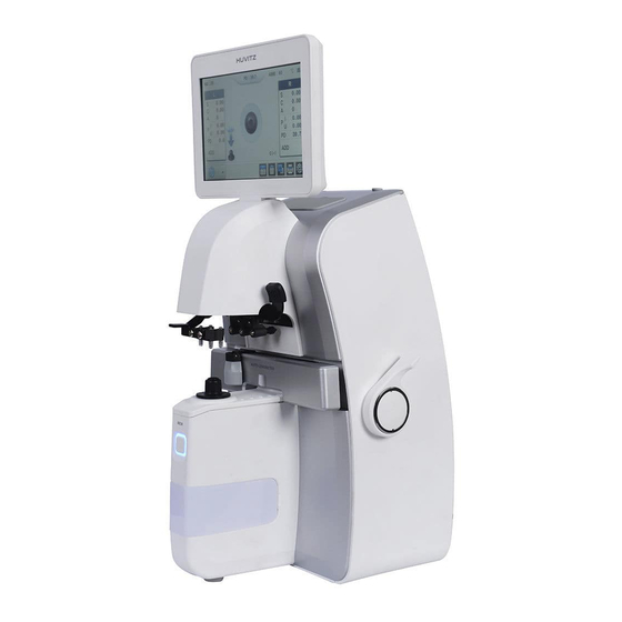
Introduction 1.1. Equipment Summary Auto Lensmeter HLM-9000 is a machine to generate Sph, Cyl and Axis information of lens by measuring refraction of the lens. Auto Lensmeter HLM-9000 also has functions to measure PD (=pupillary distance) and UV, BLUE transmission. Auto Lensmeter HLM-9000 can measure both unprocessed single lens and eyeglass lens with frames. -
Page 7: Safety Information
HLM-9000 Safety Information 2.1. Introduction Safety is primary responsibility for all people. Safe use of this equipment is a concern for installer, user, operator and administrator. Any person shall be familiarized with the contents of this User Manual before installing, using, cleaning, repairing or adjusting this equipment and its supplementary items. - Page 9 HLM-9000 It signifies a safe earthing point where safe earth is fixated on sash. For safety, connect protective earth to conductive part of class I apparatus. Alternating Current Direct Current. Serial Number Humidity Limitation Atmospheric Pressure Limitation This side up...
- Page 10 Keep away from sunlight Huvitz Symbol • Other Sign External series connection port. User can transmit saved data to other equipment of Huvitz or other devices such as a PC.
-
Page 11: Environmental Symbol
A place where the equipment can be exposed to chemical substances or flammable gas. Watch out for dust, especially metal pieces from entering the equipment. Do not disassemble the product. Huvitz will not be held responsible for any negligence regarding such action. - Page 12 Do not connect the AC power adapter before all parts are fully assembled. It can lead to a malfunction. Always pull the power cord holding the plug and not the cord. Avoid places with temperature lower than 10℃ or higher than 40℃ during normal operation. Avoid places with temperature lower than -5℃...
-
Page 13: Safety Precaution
This equipment shall be operated by or under supervision of a well-trained and capable person. Repair of this equipment shall be handled by service personnel at Huvitz or a person with equivalent certification. Customer’s care over this equipment shall be done only according to the User Manual and Service Instruction. - Page 14 Do not apply excessive pressure on cable connection. If the cable does not connect, check to see if the plug is appropriate for socket. Damaged cable plug and socket shall be repaired by certified service technician. Do not pull the cable. Always hold and pull plug when removing the cable. This equipment can be used as other international purposes for general examination of lenses in accordance with this instruction.
- Page 15 HLM-9000 CAUTION For use of equipment in rated voltage less than 125Vac, minimum 6A,Type SJT or SVT , 18/3AWG,10A, max 3.0m long : One end with Hospital Grade Type, NEMA 5-15P Other end with appliance coupler. For use of equipment in rated voltage less than 250Vac, minimum 6A, Type SJT or SVT, 18/3AWG, 10A, max 3.0m long : One end terminated with blade attachment...
-
Page 16: Feature
Feature Quick and convenient measurement of refraction and center of a lens. When measuring an eyeglass, single/both PD are measure automatically with refraction of each lens. Measurement of UV and Blue transmission of a lens. Wide range of measurement from –25D to +25D. More precise measurement with unit as small as 0.01D. -
Page 17: Instructions For Use
HLM-9000 Instructions for Use Do not hit or drop the equipment. Strong pressure might damage the equipment. Strong pressure can affect the function of the equipment. Thus, always handle with care. Install the equipment in a stable place without vibration to maintain normal condition. -
Page 18: Device Configuration And Operation Flow
Device Configuration and Operation Flow 5.1. Device Configuration - Main Parts Touch LCD Screen : Display the lens measurement screen. PD Sensor : Used to measure PD value. Lens Holder Lever : Used to operate the lens holder. To secure a lens: Lift once and lower gently. To release a lens: Lift until it clicks. - Page 19 HLM-9000 [Names of parts (I) - Front] 12. Power Switch : Switch for power on, off. [Names of Parts (II) - Back]...
- Page 20 13. RS-232 Connector : A terminal connecting to the exterior equipment 14. Power Connector : Used to connect a removal power cord. 15. USB Connector : Connection terminal for product upgrade. [Names of parts (III) – Bottom]...
-
Page 21: Device Configuration - Standard Accessories
HLM-9000 5.2. Device Configuration – Standard Accessories Printing Paper: 2 roll of paper for printing Fuse (250V 3.15A): (2) User Manual: Operation guide for users Power Cable (1.5m) Dust Preventive Cap: a cap to prevent dust from entering (1) Contact lens tweezer: a tool to pick up contact lenses... -
Page 22: Operation Flow
5.3. Operation Flow Power on 6. Equipment Installation and Preparation Page.23 ▼ 7. Button Composition Page.25 8. Screen Composition Page.28 8.1. Measurement Screen Page.28 8.2. Progressive lens Screen Page.30 8.3. Auto Detect Mode Page.31 8.4. Contact lens Screen Page.32 8.5. UV, Blue Screen Page.33 Measurement 8.6. -
Page 23: Equipment Installation And Preparation
HLM-9000 Equipment Installation and Preparation 6.1. Parts Inspection Inspect supplementary articles. Open the box and make sure all articles are there (printing paper, dust cover, lens towel, User Manual and etc.). Remove protection tapes. Remove protection tapes on lens holder, lens cap, marking lever and UV, Blue cover. -
Page 24: Screen Saver
[Screen showing an initialize error (2)] Turn on the equipment, and make sure there are not any objects on the lens cap. If a message that says, “Initialize error” is displayed as shown in [Picture: Screen showing an initialize error], check to see there are any objects placed on the lens cap or pinhole, and remove if there is any. -
Page 25: Button Composition
HLM-9000 Button Composition 7.1. Button Composition According to Measuring Mode General Lens Measurement Screen Buttons • Progressive Lens Measurement Screen Buttons • Auto Detect Mode (General/ Progressive Lens) Measurement Screen Buttons • Contact Lens Measurement Screen Buttons • UV, BLUE Lens Measurement Screen Buttons •... - Page 26 Progressive Lens Screen to measure progressive multifocal lens Auto Detect Mode Determine the type of lens (general or progressive) currently being measured, and then convert to progressive lens measurement screen automatically if the lens is a progressive lens. Contact Lens Screen to measure contact lens UV, BLUE Lens Screen to measure UV, BLUE lens...
- Page 27 HLM-9000 PRINT Print out current data and delete data information. SETUP Change screen to settings. START / STOP Start/stop measuring current data on contact lens measurement screen and save the average. Adjust current transmission to 100% on UV, BLUE measurement screen.
-
Page 28: Screen Composition
Screen Composition 8.1. Measurement Screen 3. Connection Status (USB, WIFI, DR) 1. Serial Number 2. Both Eyes PD 5. ABBE Value 4. Measurement Data 7. Measurement Status 11. Measurement Lens Activation 9. Prism Status 6. Current Measurement Mode 8. Measurement Position 10. - Page 29 HLM-9000 Measurement Data Measurement data is marked. Each article signifies the below. S: Basic refraction C: Cylinder A: Cylinder axis P: Prism X, Prism Y PD: RPD or LPD ADD (for Bi focal lens): Progressive power 1, Progressive power 2 ABBE Value Current ABBE setting is marked.
-
Page 30: Progressive Lens Screen
8.2. Progressive Lens Screen Distance Viewing Zone Measurement Position 2. Near Viewing Zone Measurement Position [Progressive lens screen composition] 8.2.1. Specifics Distance viewing zone Measurement Position Position of current measurement is indicated while searching for the center of distance viewing zone. -
Page 31: Auto Detect Mode
HLM-9000 8.3. Auto Detect Mode [Auto detect mode screen composition] 8.3.1. Specifics Automatically determine the type of lens (general or progressive) currently being measured, and then convert to progressive lens measurement screen automatically if the lens is a progressive lens. -
Page 32: Contact Lens Screen
8.4. Contact Lens Screen 1. Start/Finish Saving 2. Reliability Graph 3. Measurement Method Selection (Dry/Wet) [Contact lens screen composition] 8.4.1. Specifics Start/Finish Saving Start recording results of consecutive measurement. Start saving button will change its shape to finish saving button after pressing it. (Finish: Average of all measurement results are calculated and saved.) Reliability Graph It will show the sizes of recognized dots proportionally. -
Page 33: Uv, Blue Screen
HLM-9000 8.5. UV, BLUE Screen 1. UV, BLUE Transmission 3. UV, BLUE Activation Status 4. Transmission Status 100% 2. UV, BLUE lens measurement position guide [UV screen composition] [BLUE screen composition] 8.5.1. Specifics UV, BLUE Transmission UV, BLUE transmission of lens is indicated in a bar graph and percentage. - Page 34 INFORMATION Two wavelengths for BLUE measurements are 420nm and 450nm. UV, BLUE lens measurement position guide [UV] [Blue] [UV, BLUE screen composition] UV, BLUE Activation Status Select to measure UV transmission or BLUE transmission. Transmission Status 100% Adjust current transmission status to 100%. NOTE To minimize the error, press the button ‘Transmission Status 100%’...
-
Page 35: Setup Screen
HLM-9000 8.6. Setup Screen 8.6.1. Specifics [Setup screen composition - MEASURE] PD Mode Choose to enable PD function. - Standard: Enable the function. - Averaging: Set to equalize RPD and LPD when the difference between RPD and LPD is less than 3mm. - Page 36 Storage Mode Choose to enable a function to automatically save lens data when the center of the lens is aligned. - Auto Full: Auto-save the data from both general and progressive lenses. - Auto Nrm: Auto-save the data from general lenses. - Auto Prg: Auto-save the data from progressive lenses.
- Page 37 HLM-9000 Step SPH/CYL/ADD Set S, C and ADD value indication units. - 0.25D: Set S, C and ADD value indication unit to 0.25. - 0.12D: Set S, C and ADD value indication unit to 0.12. - 0.06D: Set S, C and ADD value indication unit to 0.06.
- Page 38 No. Display Choose whether to display customer’s serial number on screen. - On: Display on screen. - Off: Do not display on screen. Measure Display Set how to display data. - SCA: Set data to be displayed as S, C, A. - S.E: Set data to be displayed as S.E.
- Page 39 HLM-9000 INFORMATION Perfect auto-measurement function can be used when ‘Storage Mode’, ‘Printer Mode’, ‘RS 232C’ and ‘Printer’ functions are enabled. Print Frame Choose whether to include the eyeglass drawing on paper when printing. - On: Enable the function. - Off: Disable the function.
- Page 40 [Date and time setting screen] Date Choose and change date (year/month/day). Time Choose and change time (hour/minute/second). [Set up screen composition - COMMUNICATION] RS 232C Set RS-232C (external) communication protocol. - OFF: Disable the function. - Wave Line: Enable single direction communication protocol function between HLM and HRK, HDR.
- Page 41 HLM-9000 Set communication speed with outside. - 9600: Set communication speed to 9600. - 19200: Set communication speed to 19200. - 38400: Set communication speed to 38400. - 57600: Set communication speed to 57600. - 115200: Set communication speed to 115200.
- Page 42 AP PW Enter a password of access point needed during WPA2-PSK authentication to connect to Wifi network (letters of password will be displayed as * on screen.) AP PW – Verify Currently entered name and password of access point will be verified. Wifi connection will be disconnected during verification.
- Page 43 HLM-9000 [Set up screen composition - ETC] Sound Enable/disable sound function and adjust volume. - Off: Disable sound. - Low: Enable sound and set volume to low. - Mid: Enable sound and set volume to medium. - High: Enable sound and set volume to high.
- Page 44 [Set up screen composition - INFORMATION] No. Reset Reset customer serial number to 1.
-
Page 45: Measurement
HLM-9000 Measurement 9.1. General Lens [How to measure a general lens] Reset measurement status by pressing ‘CLEAR’ button ( ). Set measurement lens on the top right corner of the screen to ‘S’. (However, ‘R’ will be displayed if ‘Side Allocation’ function is set to Auto RL on User Set Up screen.) - Page 46 OFF center ALIGNMENT OK MARKING OK [Focus adjustment] Press ‘MEM’ button to save the measurement. Data will be fixated after saving the data. Pressing ‘MEM’ button once again will save and fixate modified measurement. INFORMATION ‘Storage Mode’ function is to save measurement automatically 1 second after ‘MARKING OK’ display when the function is enabled in User Set Up screen.
- Page 47 HLM-9000 INFORMATION A drawing of the lens cap without a lens will be displayed on the bottom left corner of the screen when a lens is not placed. If a drawing of the lens cap with a lens is displayed even when there is not a lens placed on the actual lens cap, restart the equipment to operate automated set up to readjust zero point.
-
Page 48: Eyeglass Lens
9.2. Eyeglass Lens [Eyeglass lens measurement] Press ‘S->R’ button ( ) to enter eyeglass lens measurement environment. ‘L’ and ‘R’ will be displayed on the top of the screen. CAUTION 1. Activated data result screen indicates the lens currently being measured, and inactivated screen indicates the opposite side lens. - Page 49 HLM-9000 CAUTION When PD function is unavailable or disabled, or when side allocation function is manual, press ‘S->R’ button ( ) to select a lens to measure. Adjust focus until ‘MARKING OK’ is displayed. After PD function is on, place the PD position censor on the center of the eyeglass frame.
-
Page 50: Progressive Multifocal Lens
9.3. Progressive Multifocal Lens 9.3.1. Structure of Progressive Multifocal Lens < A lens before processing > Lens Table Near Center Far Center [Structure of single progressive lens] INFORMATION Horizontal line of a lens shall be placed parallel to the lens table. INFORMATION As shown on the [Picture: Structure of single progressive lens] above, distance viewing zone of the lens shall be placed near the lens table. -
Page 51: Judgment Of Progressive Multifocal Lens
HLM-9000 INFORMATION Sizes of progressive multifocal lenses vary according to manufacturers. INFORMATION Some of the old type progressive lenses do not comply with 2~3mm standard toward the frame center. INFORMATION Do not pick up the lens during measurement. Fixating angle of lens holder must be maintained. -
Page 52: Distance Viewing Zone Measurement
[Progressive band for autonomous judgment] The icon on the bottom left of the screen will change as the below (‘no lens’ -> ‘progressive lens’). Then, the screen will automatically convert to progressive lens measurement screen. [Change of status icon] INFORMATION When progressive power is smaller than 1D, automated judgment might not work. -
Page 53: Near Viewing Zone Measurement
HLM-9000 Adjust the lens left-right or upward-downward so the cross mark is located on the distance viewing zone target center. Distance viewing zone power will be auto-saved when the cross mark reaches the distance viewing zone target center, and it will move on to near viewing zone measurement. - Page 54 Move the lens to near viewing zone. For an eyeglass lens with erased marker, push until the leg on the lens holder reaches the bottom frame of the eyeglass. INFORMATION For an eyeglass lens, it is advisable to pull the lens using the lens table while maintaining parallel to the lens table.
-
Page 55: Troubleshoot During Progressive Lens Measurement (Auto Detect Mode)
HLM-9000 INFORMATION (Case 1) For eyeglass lens with small frame, pull up the lens holder and pull a little more to find the near viewing zone center since the near viewing zone center is nearby the bottom frame. ([Picture: Small eyeglass lens]) - Page 56 When a general lens was determined as a progressive lens. A general lens with intense aberration can be misjudged as a progressive lens. Cause 1 Measured in the general lens mode. Countermeasure When it is difficult to find distance viewing zone. If progressive area is expanded into distance viewing zone, it is difficult to find Cause 1 the distance viewing zone.
-
Page 57: General Multifocal Lens (Bifocal Lens / Trifocal Lens)
HLM-9000 9.4. General Multifocal Lens (Bifocal Lens / Trifocal Lens) 9.4.1. Structure of General Multifocal Lens BIFOCAL LENS ① Flat-Top Bifocal Zones Distance Near ② Round Seg Bifocal zones Distance Near ③ Executive Style Bifocal Zones Distance Near TRIFOCAL LENS ①... -
Page 58: Measurement On General Screen
9.4.2. Measurement on General Screen Place a lens on the first focal center, and press ‘MEM’ button. Place a lens on the second focal center, and press ‘MEM’ button. First ‘ADD’ value will be displayed on screen. This ADD value is not a fixed value. Thus, if you are confident that this value is a true value, press ‘MEM’... -
Page 59: Contact Lens
HLM-9000 Move the lens to the second focal center, and progressive value will be measured automatically. INFORMATION If auto-measurement does not work on each stage, or if you want to measure manually, press ’MEM’ button to progress to the next step. -
Page 60: Wet Measurement
Remove moisture of contact lens using a clean lens towel. In the case of Soft Contact Lens, It can be torn easily. So, remove moisture with touches lightly. Place the lens on the Contact Lens Support. The convex surface shall face the top. Adjust so the cross mark on the screen is located on the center of the concentric circle. - Page 61 HLM-9000 - Place the Wet Measuring Kit after removing the Lens Support. Check if the reading on the kit in normal mode is “S 0D ±0.25”. - If reading has a tolerance bigger than “S 0D±0.5”, the kit is considered damaged and reading is not reliable.
- Page 62 Remove lens support and place the Kit. Turn the device into contact lens measuring mode. Press ‘DRY’ button to select the proper percentage of water content. Select the function percentage for the lens and proceed with the measurement. (38% , 45% , 58% Measurement for one-day lens selects 58% regardless of the water content.
-
Page 63: Uv, Blue Transmission
HLM-9000 9.6. UV, BLUE Transmission [How to measure UV, BLUE transmission] Press Measurement Mode button ( ), and select ‘UV, BLUE’ lens measurement mode ( Pull out the UV, BLUE cover. Press UV button on the screen, and select to activate the UV measurement area. (To measure BLUE, press BLUE button to activate the BLUE measurement area.) -
Page 64: Measuring Point Marking
NOTE UV transmission is measured based on a plate without refraction, and there can be errors when measuring lenses with refraction. NOTE When UV or BLUE transmission is not 100% without a lens, press ‘CAL’ button ( ) to readjust UV or BLUE transmission to 100%. NOTE Blue lens measuring light is in wavelength range of visible light, so measuring light is influenced by surrounding rays. -
Page 65: With Astigmatism
HLM-9000 [How to mark a measuring point] 9.7.2. With Astigmatism Place a lens on the lens cap, and move until ‘MARKING OK’ is displayed. Adjust lens to the angle on the prescription while maintaining ‘MARKING OK’. Tilt the marking lever to 90 to horizontal and mark. -
Page 66: Measurement Data Transmission Using Wifi
9.9. Measurement Data Transmission using WiFi Measurement data can be transmitted to Huvitz Co. Ltd, phoropter using a WiFi network. Data can be transmitted without direct data cable connection using this function. Thus, it does not require any additional installations or take up installation spaces as it uses wireless network. Therefore, operations such as to install two equipment in different rooms on different floors are possible. - Page 67 HLM-9000 CAUTION Use the static allocation IP Address that does not use the IP of the HDR that this device wants to access. When trying to access the device that uses the allocated IP by using DHCP function, access may not take place.
- Page 68 [WiFi AP Scan Result Screen] Press on the AP PASSWORD entry window to enter password. Press VERIFY button on ⑤ the right to confirm the password. Password verification takes up less than 10 seconds, and the result will be shown on the screen. [WiFi AP Password Verification Result Screen] Phoropter Connection Setting for lensmeter...
-
Page 69: Check Wifi Network Status
HLM-9000 [WIFi Phoropter Connection Setting Screen] Convert to User SETUP Mode, and select page 2 on network tab. ① Enter r information for phoropter to connect on each field. ② : Select if phoropter will use the data transmission function. -
Page 70: Measurement Data Transmission
: Connection failure to one or more selected phoropters. : Phoropter connection process is in progress. For user convenience, the machine will operate to make attempts to connect to AP automatically while the power is on if it is not connected to AP. Thus, user does not have to go through the AP connection process. - Page 71 HLM-9000 [Transmission Complete on AUTO Mode] After confirming the result, press OK to turn off the status screen. If there are connection errors on one or more phoropters, the setting will be converted to MANUAL without transmitting the data. If it was set to MANUAL The data will not be transmitted immediately, and current phoropter connection status screen will appear.
- Page 72 : Connected to phoropter normally. : Not connected to phoropter. : Data transmission is complete. (At times of data transmission) : Data transmission was unsuccessful. (At times of data transmission) : There is not a phoropter selected. Transmit data to a phoropter of user’s choice by pressing on the phoropter window. If the phoropter is not connected, try to reconnect by pressing the window as shown in 9.9.2.
-
Page 73: Measurement Data Transmission Using Serial
HLM-9000 9.10. Measurement Data Transmission using Serial The measured data can be transmitted externally via the serial communication and can be transmitted to HDR (phoropter) and PC using HDR-Mate (PC Program). You can use the transferred data on PC side using HDR-Mate (optional). -
Page 74: Print Format
9.11. Print Format Print format is as the below. [Print format for eyeglass lens] 1. Patient Name 2. Patient Number 3. Date and Time 4. Display the lens type 5. Lens frame display (Axis display): user setup -> PRINT FRAME -> On 6. -
Page 75: Self-Diagnosis And Maintenance/Repair
HLM-9000 Self-diagnosis and maintenance/repair 10.1. Before calling a serviceman Warning appears on the screen when there is a problem or when this device malfunctions. Take the following measures in case of the following. Contact a sales distributor after turning off the power when the device does not resume normal operation even after taking the following measures. -
Page 76: Printing Paper Replacement
10.2. Printing Paper Replacement Press the button on the side to open the cover. Cut off the paper clamped in the paper, and take out the paper roll. Place a new paper roll in the printer case. - Page 77 Place the end of the paper through the hole on the cover and close the cover. NOTE Recommend using the printing paper provided by Huvitz. If you use the similar products, it may cause malfunction and broken. ※ Replacement Part Name, Code and Spec.
-
Page 78: Fuse Replacement
Place the new fuse box in the fuse location. INFORMATION Auto Lensmeter HLM-9000 uses a 250V, T3.15AL fuse. 10.4. Storage While not use, cover up the device with the dust cover as shown in [Picture: How to store while not... -
Page 79: Disposal
HLM-9000 [How to store while not use] If you do not plan to use the device for more than a week, place the dust cap on lens cap as shown in [Picture: For long-term storage]. [For long-term storage] 10.5. Disposal... -
Page 80: Various Messages
10.6. Various Messages Message box shows information when you are measuring or this instrument is out of order. [Measuring Error screen] Measuring Error: Is displayed when there is no signal. Is displayed when there is out of range signal. Contact lens measurement, when signal is bad, appear. [Data Transmitting screen]... -
Page 81: How To Clean Pinhole
Do not use liquid such as alcohol or acetone as it can dissolve the adhesive on the pinhole. If the S, C and A values are not 0 after cleaning the pinhole, please inquire with an authorized dealer or Huvitz Service Department. -
Page 82: Major Specification
Major Specification • Measurement Range Spherical Power 0D ~ ±25D (0.25/0.12/0.06/0.01) Cylinder Power 0D ~ ±10.00D (0.25/0.12/0.06/0.01) Cylinder Axis ~ 180 step) Progressive Power 0 ~ 10D (0.25/0.12/0.06/0.01) Prism 0 ~ 20∆ (0.25/0.12/0.06/0.01) • Wireless I/F Protocol IEEE802.11b 2.4GHz WiFi Security mode WPA2-PSK IP configuration... -
Page 83: Emc Information
Manufacturer announcement – electromagnetic waves tolerance electromagnetic waves tolerance HLM-9000 is to be used in the below designated electromagnetic wave environment. HLM-9000 customer and user need to guarantee that the HLM-9000 will be used in this type of environment. Tolerance test IEC 60601... - Page 84 Other UT is the a.c. power voltage for before approving the test level. Electromagnetic waves tolerance HLM-9000 is to be used in the below mentioned electromagnetic wave environment. HLM-9000 purchaser or user needs to confirm whether HLM-9000 is sued at this environment.
- Page 85 If the measured field strength in the location in which the HLM-9000 is used exceeds the applicable RF compliance level above, the HLM- 9000 should be observed to verify normal operation. If abnormal performance is observed, additional measures may be necessary, such as re-orienting or relocating the HLM-9000.
- Page 86 RF transmitter, field inspection is required. If the electric intensity used by the HLM-9000 that is measured at the outside of the shielded location exceeds 3 V/m, then it is necessary to observe and verify whether HLM-9000 operates normally. If abnormal operation is observed, then re-place HLM-9000 or use other shielded location that has increasingly higher RF shield effect and filter decrease.
-
Page 87: Service Information
Seller Phone: Model Number: Serial Number: If you have trouble contacting the place of purchase, contact the service department at Huvitz directly using the addresses and phone numbers below. How to Contact HUVITZ Co., Ltd 38, Burim-ro 170beon-gil, Dongan-gu, Anyang-si, Gyeonggi-do, 14055, Republic of Korea... - Page 88 EU Representative Medical Device Safety Service GmbH (MDSS) Schiffgraben 41, 30175 Hannover, Germany Tel: +49-511-62628630 Fax: +49-511-62628633...
Need help?
Do you have a question about the HLM-9000 and is the answer not in the manual?
Questions and answers