Table of Contents
Advertisement
Advertisement
Table of Contents

Subscribe to Our Youtube Channel
Related Manuals for Huvitz Excelon CAB-4000


Summary of Contents for Huvitz Excelon CAB-4000
- Page 1 Excelon Operator’s Manual Operator’s Manual Excelon-Auto Blocker...
-
Page 2: Important Notice
HUVITZ reserves the right to make changes in its products or product specifications at any time without prior notice and is not required to update this documentation to reflect such changes. -
Page 3: Table Of Contents
Excelon Operator’s Manual Contents IMPORTANT NOTICE ..................2 1. Introduction ....................6 1.1 System Configuration................6 1.2 Main Features ..................6 1.3 Classification ................... 7 2. Safety Information..................8 2.1 Introduction..................... 8 2.2 Safety Symbols ..................9 2.3 Environment factors ................10 2.4 Safety Precaution .................. - Page 4 Excelon Operator’s Manual 5.2.3 Job Management................25 5.2.4 Command Menu ................28 5.3 Design of spectacles ................30 5.3.1 LAYOUT..................30 5.3.2 Edging ..................... 40 5.4 Blocking....................46 5.5 Usage for the different types of lenses..........47 5.5.1 Optic lens..................47 5.5.2 Progressive lens including the Digital Scanning ......
- Page 5 Excelon Operator’s Manual 8.3 TRACER ....................76 8.4 TRACER-SIM..................77 9. Maintenance ....................77 9.1 “It is needed to setup prism” message..........77 9.2 “Remove the object on the table and then turn off/on” message..79 9.3 Blocking Position calibration............... 79 9.4 Blocking axis calibration ..............
-
Page 6: Introduction
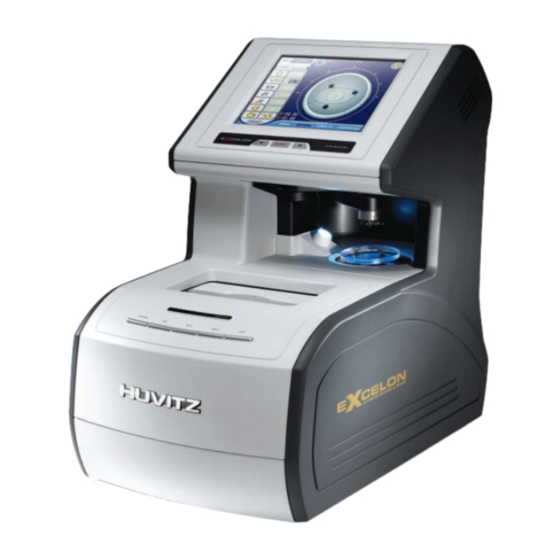
Excelon Operator’s Manual 1. Introduction 1.1 System Configuration • Auto Blocker (CAB-4000) This product is Auto Blocker CAB-4000, lenses can be checked and blocked in automatically. So the CAB-4000 eliminates the need for manual inspection and blocking of the lens. Also, with the CAB-4000 a frame can be read in simple step. 1.2 Main Features •... -
Page 7: Classification
Excelon Operator’s Manual • The Digital Scanning technology can scan a frame shape for a demo lens without a conventional tracer. This provides you an enormous convenience and a time saving. • A maximum one thousand of frames are memorized in the permanent memory. Therefore, users can retrieve them whenever they want. -
Page 8: Safety Information
Excelon Operator’s Manual 2. Safety Information 2.1 Introduction Safety is everyone’s responsibility. The safe use of this equipment is largely dependent upon the installer, user, operator, and maintainer. It is imperative that personnel study and become familiar with this entire manual before attempting to install, use, clean, service or adjust this equipment and any associated accessories. -
Page 9: Safety Symbols
Excelon Operator’s Manual 2.2 Safety Symbols The International Electro technical Commission (IEC) has established a set of symbols for medical electronic equipment, which classify a connection or warn of any potential hazard. The classifications and symbol s are shown below. Save these instructions I and O on power switch represent ON and OFF respectively. -
Page 10: Environment Factors
Excelon Operator’s Manual 2.3 Environment factors Avoid the following environments for operation or storage: Where the equipment is exposed to water vapor. Don’t operate the equipment with a wet hand. Where the temperature changes extremely. - Operation Temperature: 10 ~ 40°C (Humidity : 50 ~ 80%) - Storage Temperature : -20 ~ 85°C (Humidity : 50 ~ 80%) Where the humidity is extremely high or there is a ventilation... -
Page 11: Safety Precaution
Excelon Operator’s Manual Don’t plug the AC power cord into the outlet before the connection between devices of the e q u i p m e n t c o m p l e t e d . This can generate the defect. Where the equipment is subject to excessive shocks or vibrations. - Page 12 ③ The equipment must be operated only by, or under direct supervision of a properly trained and qualified person. ④ The service technician of Huvitz or the technician authorized by Huvitz may only carry out modifications of this equipment. ⑤ Customer maintenance of this equipment may only be performed as stated in the User’s Manual and Service Manual.
- Page 13 Excelon Operator’s Manual If the customer makes use of other accessories, use them only if their safe usability under technical aspect has been proved and confirmed by Huvitz or the manufacturer of the accessory. ⑨ Only person who has undergone proper training and instructions are authorized to install, use, operate, and maintain this equipment.
- Page 14 Excelon Operator’s Manual manufacturer and this manual. WARNING • Be sure not to move the hands into the working area during blocking. Otherwise, the person may be seriously hurt. • Be sure not to block without a block in the block holder, otherwise the lens may be broken or scratched.
- Page 15 Excelon Operator’s Manual • Be sure that the stylus of frame reader is not interfered with the human body or other objects during the operation. Otherwise, it may cause the hurt or malfunction of the product. • Do not force on the stylus of frame reader. It may cause the malfunction of the product.
-
Page 16: System Configurations
Excelon Operator’s Manual 3. System Configurations 3.1 Front View Main display window Frame Main Key Pad Reader Module Lens Supporter Key for Frame Reader Blocking Arm 3.2 Rear View Main Power Input... -
Page 17: Standard Accessory (Tool Box)
Excelon Operator’s Manual 3.3 Standard Accessory (Tool Box) Lens Supporter Lens Supporter for Frame Change Lens Supporter Standard Frame Touch Pen For Digital Scanning Standard Pattern Pattern Holder NOTE • Only Use 3M LEAP-III™ as the Block Tape in order to assure the proper axis positioning. -
Page 18: Installation Procedure
Excelon Operator’s Manual 4. Installation Procedure 4.1 Installation ① Remove the shock-absorbing material from the packing box and pull out the auto blocker carefully. ② Remove the shock-absorbing material from the blocking arm and the workspace of Stylus. ③ Plug the Power Cable into the receptacle at the back of the product and turn on the power to check the initial operation. -
Page 19: Operation
Excelon Operator’s Manual 5. Operation 5.1 Frame Reader Module MATERIAL LEFT BOTH RIGHT STOP • MATERIAL Select one of METAL, PLASTIC or OPTYL. Before the frame is traced, choose one of the above items. The specified values are used in Edger for the size adjustment. ☞... - Page 20 Excelon Operator’s Manual Operation Tips • Refer to the messages for the frame reader module which are shown the top of main display with beep sound. These messages enable you to take a next action. • The data will be automatically transmitted after finishing the tracing. •...
- Page 21 Excelon Operator’s Manual Frame Tracing ① Place the frame between the upper grippers and the lower grippers. ② Move the frame in order that the bridge of frame is located at the central position between the left and right side grippers. ③...
-
Page 22: Blocker Module
Excelon Operator’s Manual 5.2 Blocker Module ◀ ▶ Numeric Pad BLOCKING... -
Page 23: Key Functions
Excelon Operator’s Manual Job Menu Right / Left Items for Layout Menu Items Buttons for switching LAYOUT / EDGING 5.2.1 Key functions • BLOCK Press this button to block the lens. If the option for the output to the edger is on, it sends data and then blocks the lens. -
Page 24: Numeric Value
Excelon Operator’s Manual • ▶ Function Normal Mode Increase the led power Grid Mode Increase the size of grid Dialog Box Mode Respond with an affirmative reply. 5.2.2 Numeric value Increment Decrement ☞ The numeric pad is open if you press the digital value which you want to change. •... -
Page 25: Job Management
Excelon Operator’s Manual • ▲ Increase the value by the specified step. • ▼ Decrease the value by the specified step. • ◀ Move the cursor to the left side. • ▶ Move the cursor to the right side. 5.2.3 Job Management •... - Page 26 Excelon Operator’s Manual • Dialog Box for the job management Working Job ☞ Working Job is the job which is being loaded and edited by user. You can create a new working job from the frame reader, internal jobs, and also memory jobs. ☞...
- Page 27 Excelon Operator’s Manual Memory Job ☞ There are SQUARE, ELLIPSE, SAMPLE, CIRCLE, and PENTAGON in the internal...
-
Page 28: Command Menu
Excelon Operator’s Manual job. 5.2.4 Command Menu • MENU USER MENU Go into the display of user option. FACTORY MENU Go into the display of factory settings. USER MENU Go into the display of calibration. • OPTION BOX CENTER / OPTICAL CENTER Choose the style of blocking. - Page 29 Excelon Operator’s Manual Transpose the sign of the cylindrical value. ! CAUTION • The CYL sign and the CYL axis of your prescription should be matched with those of the main display. Otherwise, the prescription axis could be incorrect GRID Display or Hide the grid •...
-
Page 30: Design Of Spectacles
Excelon Operator’s Manual 5.3 Design of spectacles 5.3.1 LAYOUT You should specify the lens type, bridge size, pupil distance and the optic height, etc at the layout display. Lens type Info. box Bridge Size Value box Pupil Distance Value box Height Value box Angle... - Page 31 Excelon Operator’s Manual WARNING • Be sure not to touch the lens after the measurement is completed. Otherwise, the pupil distance isn’t correct the lens blocked. • If the lens move any place a little after finishing the measurement, try to measure it again.
- Page 32 Excelon Operator’s Manual • Pupil Distance Set the pupil distance - Set the pupil distance for both eyes - binocular - Set the singular pupil distance for the right eye - monocular - Set the singular pupil distance for the left eye - monocular •...
- Page 33 Excelon Operator’s Manual ! CAUTION • The CYL sign and the CYL axis of your prescription should be matched with those of the main display. Otherwise, the CYL axis fitted could be incorrect • Resize : Digital Edit Set the resize. - diameter enlargement - Circumference enlargement •...
- Page 34 Excelon Operator’s Manual • Free Editing Mode Arrow buttons for resizing Pop up the Numeric Pad...
- Page 35 Excelon Operator’s Manual NOTE • In case of Two Eye Tracing, the value of FPD will be automatically transmitted and displayed. • In case of pattern tracing, be sure to change the initial value to the actual Bridge Size. • Measure the Bridge Size as (B) instead of (A). Remember that the Bridge Size is not from frame to frame, but from lens to lens, The saved frame data is stored in the internal permanent memory.
- Page 36 Excelon Operator’s Manual Operation Tips • In case of One Eye Tracing, it is recommended to input the Bridge Size instead of FPD. • If you get the tracing data with tilted axis of Pattern (Demo Lens) or if you want to change the axis of rimless frame, the axis rotation ( ) of Digital Pattern will be very much convenient for the Layout Job.
- Page 37 Excelon Operator’s Manual area included within the frame. Sometimes too small frame shape might cut out the near vision area. In this case, the digital pattern provides the enlargement of the frame shape. You can execute the Frame Tracing while designing the layout and the edging.
- Page 38 Excelon Operator’s Manual In digital pattern editing, if you change one of the changeable elements, the original data will be shown with violet color. Original Contour Changed Contour The following two safety checking is executed before blocking an adaptor in case that the safety checking is on in the configuration settings.
- Page 39 Excelon Operator’s Manual Lens Adapter Interference (II) Use small lens adaptor. Lens Adapter Interference (III) Edging impossible. Use different frame data.
-
Page 40: Edging
Excelon Operator’s Manual 5.3.2 Edging You should specify the lens material, the edging type, and the position of edgin g, etc, at the edging display. Lens Material Info. box Safety Edging Info. box Edging type Info. box Polishing Info. box Position Value box Size... - Page 41 Excelon Operator’s Manual material of lens is matched with the job options selected in the display before starting blocking. - Polycarbonate - Hi-Index Lens - Tri-Vex lens • Safety Edging Choose one of the normal edging and the safe edging. - non-safety edging - safety edging - for the fragile lens like a glass material...
- Page 42 Excelon Operator’s Manual - Flat Edging - for a rimless spectacles In case of Semi-Rimless Edging , the grooving depth and width can be adjusted by changing the default value in “Edging Default” Menu. • Polishing Choose one of polishing and non-polishing. - No polishing - Polishing •...
- Page 43 Excelon Operator’s Manual Operation Tips • The value of the edging options affects the final output as followings : [ Ratio(%) mode from the front side ] • Like the above picture, if the operator use ratio(%) mode from the Front side about a so thin lens, the machining of the thinnest part could be dangerous.
- Page 44 Excelon Operator’s Manual ! NOTE Base Curve Base Base [Base curve mode] Curve Curve (+) lens (-) lens • In the base curve mode, base curves of (+) lenses and (-) lenses exist the opposite side of each of them. In this mode, the bevel or grooving line always passes the mid of the thinnest area which is located at the midst zone of (-) lenses and is located at the edged zone of (+) lens.
- Page 45 Excelon Operator’s Manual • Rear Safety Beveling Choose the safety beveling of the rear side. - safety beveling(normal) - safety beveling(Large) - no safety beveling CAUTION • The safety beveling for glass lenses should be performed both at front and rear side.
-
Page 46: Blocking
Excelon Operator’s Manual 5.4 Blocking The procedures for blocking are as followings : Stick the tape on the lens adaptor. Insert the lens adaptor into the lens adaptor setter. Press the “BLOCK” key. First, try to send data to the external edger system if this exporting function is Block the lens after completing the communication. -
Page 47: Usage For The Different Types Of Lenses
Excelon Operator’s Manual 5.5 Usage for the different types of lenses We’ll explain you the blocking procedures for the different types of lens such as a normal lens, a bi-focal lens, a progressive lens and an unusual lens from now on. We’ll add some tips such as the Digital Scanning, the Digital Pattern and the auto recognition etc, at the same time. - Page 48 Excelon Operator’s Manual [ STILL IMAGE ] Lens Diopter Optic Center with yellow color NOTE • The live image will be changed to the still image after pressing the MEASURE button. That’s why that the read frame is always displayed horizontally parallel regardless of the location and the orientation of the lens.
- Page 49 Excelon Operator’s Manual NOTE • If you press the numeric area of a PD or an optic height one time, the focus is set on there. You can change a PD and an optic height by pressing RIGHT and LEFT arrow keys at this moment. You can see concurrently the effect of changing PD or an optic height.
-
Page 50: Progressive Lens Including The Digital Scanning
Excelon Operator’s Manual 5.5.2 Progressive lens including the Digital Scanning NOTE • You can use a pattern jib to read the pattern or the demo lens as you did in the past. But, this paragraph explains you how to use the Digital Scanning, and how convenient it is. - Page 51 Excelon Operator’s Manual Step 3. Press DIGITAL SCAN item of the COMMAND menu to read a frame. Step 4. Change to the normal lens supporter. Step 5. Put a progress lens on a lens supporter and then change to the Progressive Mode.
- Page 52 Excelon Operator’s Manual Eye Point [ Semi-Automatic ] [ Automatic Dectection ] Step 6. Change a PD and an optic height if necessary. NOTE • If you press the numeric area of a PD or an optic height one time, the focus is set on there.
-
Page 53: Bi-Focal Lens Including The Digital Pattern
Excelon Operator’s Manual Step 8. Press BLOCK key, and then press a RIGHT key to send the data to an edger. Cancel sending BLOCKING Confirm sending Step 9. Clamp the blocked lens at an edger and press START key to start edging. Step 10. - Page 54 Excelon Operator’s Manual Step 4. Put a lens on a lens supporter. [ LIVE IMAGE ] Step 5. Change to the Bi-Focal Mode. ☝ [ Optical Blocking for a Bi-focal lens ]...
- Page 55 Excelon Operator’s Manual Step 6. Change a PD and an optic height if necessary. NOTE • If you press the numeric area of a PD or an optic height one time, the focus is set on there. You can change a PD and an optic height by pressing RIGHT and LEFT keys at this moment.
- Page 56 Excelon Operator’s Manual CAUTION • You can start or finish the Digital Pattern by pressing the icon of the Digital Pattern • The Digital Pattern enables you to change a frame shape. You can enlarge the shape to include the near vision area of bi-focal lens or progressive lens. Or, You can fit the shape to be in harmony with the face of a patient.
-
Page 57: Auto Recognition Of Lens Type
Excelon Operator’s Manual 5.5.4 Auto recognition of lens type You don’t’ need to press the button of lens type if you turn on the function of auto recognition. ☞ This machine detects the lens type of a lens with a few seconds, and shows you a prompt message at the top of the display. -
Page 58: User Menu
Excelon Operator’s Manual 6. User Menu If pressing MENU >> USER MENU, you can go into the User Menu display. User Menu consists of SYSTEM INFO, BASCI INFO, LAYOUT DEFAULT, EDGING DEFAULT, TRACER DEFAULT and LENSMETER DEFAULT. Page Info Save Up/Down Page EXIT Categories... -
Page 59: System Info
Excelon Operator’s Manual • Up/Down Page The Up/Down Page enables to move the previous page or the next page if exists. • EXIT The EXIT button enables to return to the previous page. 6.1 System Info • Main S/W Version The version of the main GUI board •... -
Page 60: Basic Info
Excelon Operator’s Manual • Frame Reader The version of a tracer module 6.2 Basic Info • Language Select the language. • EDGER1 I/F Turn on or off the communication with EDGER 1... - Page 61 Excelon Operator’s Manual • EDGER2 I/F Turn on or off the communication with EDGER 2 • Auto Brightness Turn on or off the function of the auto brightness for the light source. • Auto Recognition Turn on or off the function of the lens recognition which decides automatically the lens type such as normal lens, bi-focal lens, progressive lens and so on.
-
Page 62: Layout Def
Excelon Operator’s Manual 6.3 LAYOUT DEF • Default Side Select the default side for a new job. • Default Vision Mode Select the default lens type for a new job. • Blocking Mode Select the default block mode for a new job. •... - Page 63 Excelon Operator’s Manual Select the default input style for the PD value • Bridge Size Set the default bridge size for a new job. • Both PD Set the default binocular PD for a new job. • Single PD Select the default monocular PD for a new job. •...
-
Page 64: Edging Def
Excelon Operator’s Manual • HEIGHT > Delta Y Set the default Delta Y for the optical height • HEIGHT > Boxed Height Set the default Boxed Height for the optical height • HEIGHT > Mixed Height Set the default Mixed Height for the optical height •... - Page 65 Excelon Operator’s Manual • Lens Material Set the default lens material • Edging type Set the default Edging type • Polish at Bevel Set the default setting of Polish for a bevel job • Polish at Rimless Set the default setting of Polish for a rimless. ( 2/5) •...
- Page 66 Excelon Operator’s Manual Set the default settings or values for a grooving job.
- Page 67 Excelon Operator’s Manual (4/5) Set the default settings or values for a safety beveling job.
- Page 68 Excelon Operator’s Manual (5/5) • Blocking Calibration for a normal lens Set the value for adjusting the position of blocking for a normal lens. The unit is • Blocking Calibration for a marked lens Set the value for adjusting the position of blocking for a progressive lens, a bi-focal lens, and 3-dot lens.
-
Page 69: Lensmeter Def
Excelon Operator’s Manual 6.5 LENSMETER DEF • Cyl Display Format Set the default format for displaying the cylindrical power. • Lens supporter Set the default lens supporter which you use. • Diopter Step Set the Diopter Step for displaying a lens power. •... -
Page 70: Factory Menu
Excelon Operator’s Manual 7. Factory Menu If pressing MENU >> FACTORY MENU, you can go into the Factory Menu display. Factory Menu consists of BLOCKER, LENSMETER, LCD and TRACER. 7.1 Blocker • Center Shift X Set the mechanical offset x of the block adapter. This value is used to adjust a mechanical error. -
Page 71: Lensmeter
Excelon Operator’s Manual • Shift Angle Set the mechanical angular error of the block adapter. This value is used to adjust a error of a mechanical error. Refer to Section 9.4 • LED Power Set the LED Power for the observation channel. Don’t change it by yourself. 7.2 Lensmeter •... -
Page 72: Eeprom
Excelon Operator’s Manual 7.3 EEPROM • FACTORY BACKUP Show if there is a factory backup or not • USER BACKUP Show if there is a user backup or not • BACKUP FACTORY DATA Save a current eeprom data into the flash memory. Don’t press this button by yourself. •... -
Page 73: Calibration Menu
Excelon Operator’s Manual Set the user backup data to a current eeprom data. 8. Calibration Menu If pressing MENU >> Calibration MENU, you can go into the Calibration Menu display. Calibration Menu consists of BLOCKER, LENSMETER, TRACER, TRACER-SIM and AGING. -
Page 74: Lensmeter
Excelon Operator’s Manual 8.1 Lensmeter LM Motor Position Categories Result Values Buttons to move LM motor • LIVE IMAGE Shows the live image which is captured by the lensmeter camera. • LIVE IMAGE Shows the live image which is captured by the lensmeter camera. •... -
Page 75: Blocker
Excelon Operator’s Manual Press the diopter box after finishing calculating. Set the lens diopter and then press ‘ENTER’ to save the specified diopter. • SETUP PRISM Set the prism power • REPEAT Calculates and displays the repeatability of the test lens. •... -
Page 76: Tracer
Excelon Operator’s Manual CENTER are explained in section 9.3 ~ section 9.7. 8.3 TRACER You can calibrate the tracer module using this page. • STROKE Start calibrating the stroke. Follow the instruction shown on the display. • FRAME Start calibrating the stroke. Set the FRAME jib at the gripper of the tracer module and then follow the instruction shown on the display. -
Page 77: Tracer-Sim
Excelon Operator’s Manual 8.4 TRACER-SIM This page enables you to check all components of the tracer modules. Follow the instruction on the display. 9. Maintenance CAUTION • Don’t put anything on the lens supporter while the machine is starting up. Otherwise, it might be malfunctioned. - Page 78 Excelon Operator’s Manual Step 1. Go into the Lensmeter Calibration Display by press MENU >> CALIBRATION >> LENSMETER Step 2. Press ‘D’ button at the left upper side to move the lensmeter block. Step 3. Press 3 buttons for Lensmeter functions sequentially which are “LIVE IMAGE”, “SHOW INFO”...
-
Page 79: Remove The Object On The Table And Then Turn Off/On" Message
Even though there is nothing on a lens supporter, if you see “Remove the object on the table and then turn off/on” message at start-up, be in contact with your local distributor or the Huvitz service department. 9.3 Blocking Position calibration... -
Page 80: Blocking Axis Calibration
Excelon Operator’s Manual you see in the above picture, move the cross marker to locate the center of the hole using 4 arrow buttons at the bottom. Step 5. If you moved the cross marker, press the save button at a top area to apply your calibration. -
Page 81: Calibration Of The Internal Lensmeter's Center
Excelon Operator’s Manual Step 4. Put the lens to be placed at the center of the cross and paralleled along the horizontal line. Step 4. Click “BLK CENTER” button. Step 5. Take it out and examine the blocked angle. Step 6. Go into “FACTORY MENU > BLOCKER” page. Step 6. - Page 82 Excelon Operator’s Manual Step 5. Go into the blocker calibration display clicking “Calibration > BLOCKER” buttonsStep 6. Press “LM CENTER” button. Step 7. If the center dot and the center of the cross marker aren’t coincided, move the cross marker using 4 arrow buttons in a bottom area. Step 8.
-
Page 83: Calibration Of The Internal Lensmeter's Axis
Excelon Operator’s Manual 9.6 Calibration of the internal lensmeter’s axis It is needed for you to calibrate the axis of the internal lensmeter if the blocked axis isn’t correct for a optic lens. Step 1. Reset the misaligned angle 0 at “FACTORY MENU>LENSMETER”Step 2. Mark a lens with a cylindrical power using your lensmeter. -
Page 84: Touch Panel Calibration
Excelon Operator’s Manual 9.7 Touch Panel calibration It is needed for you to calibrate the position of a touch panel if the display of LCD and the position of Touch Panel aren’t coincided. [ Touch Coordinate] Step 1. Go into the Touch Panel calibration by pressing “MENU > FACTORY MENU >... -
Page 85: Miscellaneous
Excelon Operator’s Manual 9.8 Miscellaneous • To change a fuse When you are changing a fuse, make sure that it’s 250T, 3.15AL. You can find them under the power plug of the backside of the product. - Page 86 Excelon Operator’s Manual Standard Accessory Operator’s Manual ············································································ 1 Normal lens supporter············································································1 Lens supporter for frame change··································································1 Lens supporter for Digital Scanning·······························································1 Standard Frame (for Frame Reader Calibration) ············································1 Standard Pattern (for Frame Reader Calibration) ·············································1 Pattern Holder ·····················································································1...
-
Page 87: Specification
Excelon Operator’s Manual Specification 항목 세부 Spec. 비고 Lens Analysis • Method Both Projected image and transmitted Unit image • Lens diameter Max: 80mm dia, Min: 18mm • Camera CCD b/w • Display 10.4inch Color LCD 800x600 • power measurement SPH, -20D ~ +15D, CYL: ±... - Page 88 Excelon Operator’s Manual Ext Port • Com PORT 1 Edger 1 • Com PORT 2 Edger 2 • Com PORT 3 Tracer Out • Com PORT 4 Bar Code Reader • Com PORT 5 Tracer Debugging & Upgrade • Com PORT 6 Blocker debugging &...
- Page 89 Excelon Operator’s Manual Drawings of System...
Need help?
Do you have a question about the Excelon CAB-4000 and is the answer not in the manual?
Questions and answers