Table of Contents
Advertisement
Quick Links
UM2673
User manual
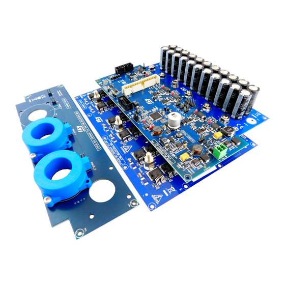
5 kW low voltage high current inverter for automotive motor control applications
Introduction
The STEVAL-TTM001V1 evaluation kit is designed to demonstrate the highly efficient ST automotive-grade 100 V STripFET F7
series Power MOSFETs and BLDC motor driver IC operating in typical automotive low voltage (car battery up to 48 V), high
current motor control applications.
The kit includes a board to sense and condition currents, and a driver board with a programmable
L9907
FET driver with full
diagnostics to manage all 36
STH315N10F7
Power MOSFETs on a power board also included in the kit.
The driver board also includes an ST motor control connector to interface with any compatible ST motor control board (not
included in the kit), and various other connectors and jumpers for monitoring and protection, motor position feedback
information, and auxiliary power.
Figure 1.
STEVAL-TTM001V1 evaluation kit
UM2673 - Rev 1 - January 2020
www.st.com
For further information contact your local STMicroelectronics sales office.
Advertisement
Table of Contents

Related Manuals for ST STEVAL-TTM001V1


Summary of Contents for ST STEVAL-TTM001V1
-
Page 1: Figure 1. Steval-Ttm001V1 Evaluation Kit
Power MOSFETs on a power board also included in the kit. The driver board also includes an ST motor control connector to interface with any compatible ST motor control board (not included in the kit), and various other connectors and jumpers for monitoring and protection, motor position feedback information, and auxiliary power. -
Page 2: Evaluation Kit Features
• Maximum power 5 kW at 48 V. • Isolated current sensing, bus voltage and temperature monitoring. Target applications STEVAL-TTM001V1 kit is designed for applications involving motor drives for electric traction, such as: • urban electric cars • small city buses •... -
Page 3: Safety And Operating Instructions
UM2673 Safety and operating instructions Safety and operating instructions General terms All operations involving transportation, installation and use, as well as maintenance, has to be carried out by skilled technical personnel (national accident prevention rules must be observed). For the purpose of these basic safety instructions, "skilled technical personnel"... -
Page 4: Evaluation Kit Overview
L9907 three phase gate driver able to provide full diagnostic and programmable parameters via SPI. The system includes a bulk capacitor board and a current sensing board. The STEVAL-TTM001V1 can be interfaced with any ST MCU evaluation board with embedded ST motor control connector and ST FOC firmware library support. -
Page 5: Steval-Ctm004V1 Power Board
UM2673 STEVAL-CTM004V1 power board STEVAL-CTM004V1 power board The STEVAL-CTM004V1 power board of the evaluation kit has 36 STH31*N10F7 N-channel Power MOSFETS in the H²PAK-6 package. A gate resistor is placed near each power MOSFET to eliminate parasitic oscillation. A pull-down resistor between the gate and the source of each transistor helps to avoid capacitive coupling driving the transistor and unwanted switch-on when gate is floating. -
Page 6: Figure 4. Package And Internal Schematic Diagram
UM2673 STH315N10F7 N-channel Power MOSFET characteristics • Excellent figure of merit (FoM) • Low C ratio for EMI immunity • High avalanche ruggedness Figure 4. Package and internal schematic diagram UM2673 - Rev 1 page 6/42... -
Page 7: Steval-Ctm007V1 Driver Board
UM2673 STEVAL-CTM007V1 driver board STEVAL-CTM007V1 driver board Figure 5. STEVAL-CTM007V1 driver board functional blocks 1. connections to power board 2. motor control connector 3. ENC/HALL connector 4. ICS connector compatible with STEVAL-CTM008V1 5. L9907 driver 6. 3V3 DC/DC regulation 7. 5V DC/DC regulation 8. -
Page 8: L9907 Gate Driver Characteristics
UM2673 L9907 gate driver characteristics Table 2. NTC electrical characteristics Symbol Parameter Test Condition Unit Resistance T = -40°C 105.7 kΩ Resistance T = 25°C kΩ Resistance T = 100°C 0.426 kΩ B- constant T = 25°C to 50°C 3500 Operating temp range °C L9907 gate driver characteristics... -
Page 9: Bus Link Capacitor Board And Current Sensing Board
UM2673 Bus link capacitor board and current sensing board Bus link capacitor board and current sensing board STEVAL-CTM005V1 bus link capacitor board In EV inverter systems, bus link capacitors reduce ripple current and suppress voltage spikes caused by leakage inductance and switching operations. These capacitors provide a low impedance path for the ripple currents caused by output inductance load, the bus voltage and PWM frequency. -
Page 10: Figure 7. Steval-Ctm008V1 Current Sensing Board
UM2673 STEVAL-CTM008V1 current sensing board Figure 7. STEVAL-CTM008V1 current sensing board UM2673 - Rev 1 page 10/42... -
Page 11: How To Set Up The System
How to set up the system Follow the steps below to set up the evaluation kit. Note: The following boards referenced below are part of the STEVAL-TTM001V1 evaluation kit and are not available for separate sale: • STEVAL-CTM004V1 power board •... -
Page 12: Figure 8. Current Sensing Connector (Con2 On Driver Board)
UM2673 Connectors • Connectors for external signals – CON8 (ENC/HALL connector): to receive external signals from Encoder/Hall sensors and provides +3V3 or +5V supply voltages. – CON2 (CURRENT SENSING connector): to receive current signals from the external current sensor board and provide a +5V supply voltage. Figure 8. -
Page 13: Signal Leds
UM2673 Signal LEDs Table 4. Motor control connector pinout Pin number Pin name / Function Pin number Pin name / Function FAULT Ground Ground ADC_W PWM_U_H Ground Ground Not connected PWM_U_L Not connected Ground Not connected PWM_V_H Not connected Ground PWM_V_L Heatsink temperature signal Ground... -
Page 14: Spc5 Software Development Tools
UM2673 SPC5 Software Development Tools SPC5 Software Development Tools This evaluation kit is compatible with latest automotive Motor Control FOC Library SPC5-MCTK-LIB and with the SPC5-STUDIO IDE tool. RELATED LINKS SPC5-MCTK-LIB SPC5 Motor Control Tool Kit FOC Library SPC5-STUDIO Code Generator, Quick resources configurator and Eclipse development environment for SPC5 MCUs Firmware for SPC560P50L3 You can use the SPC5Studio IDE tool to customize the FOC library (installed together with the SPC5-MCTK-LIB FW package). - Page 15 UM2673 Firmware for SPC560P50L3 Parameter Value Unit U,V,W driver disabled Force same values for U, V, W driver U,V,W driver disabled Use STGAP1S gap drive UM2673 - Rev 1 page 15/42...
-
Page 16: Experimental Measurements
UM2673 Experimental measurements Experimental measurements The experimental results were obtained by testing the system at maximum power rating. The power board was mounted with a heatsink (manuf.: ABL Components; manuf. order code: 159AB2000B; Rth: 0.36 °C/W; dimensions: 200x160x40mm, or equivalent), using a thermal interface material with high thermal conductivity (1300 W/mK) to form a natural convection cooling system. -
Page 17: Figure 11. Measured Temperatures Of U_Phase Power Mosfets
UM2673 Experimental measurements Figure 11. Measured temperatures of U_phase Power MOSFETs The following table shows the MOSFET maximum, minimum and average temperature values. Table 8. Measured case temperatures of the STH315N10F7 power MOSFETs High Side Uphase devices Low Side Uphase devices Case Temperature [°C] max. -
Page 18: Steval-Ttm001V1 Kit Schematic Diagrams
UM2673 STEVAL-TTM001V1 kit schematic diagrams STEVAL-TTM001V1 kit schematic diagrams UM2673 - Rev 1 page 18/42... -
Page 19: Power Board Schematic Diagrams
10.1 Power board schematic diagrams Figure 12. Power board schematics DC_BUS+_PW_U LS_GATE_U LS_GATE_U LS_Source_U LS_Source_U NTC+_U_PW NTC+_U_PW NTC-_U_PW NTC-_U_PW HS_GATE_U HS_GATE_U HS_Source_U HS_Source_U HS_GATE_U Q H 1 S_GATE_U HS_GATE_U Q H 3 S_GATE_U HS_GATE_U HS_GATE_U 0.033uF N.M. NTC+_U_PW HS_Source_U 4.7k Phase_U Out_PHASE_U NTC-_U_PW... -
Page 20: Bulk Capacitor Board Schematic Diagrams
10.2 Bulk capacitor board schematic diagrams Figure 13. Capacitor board schematics PADs for High Current - 200A DC_BUS+_U DC_BUS+_V DC_BUS+_W TW10 TW11 DC_BUS+ DC_BUS- DC_BUS-_W DC_BUS-_U DC_BUS-_V... -
Page 21: Driver Board Schematic Diagrams
10.3 Driver board schematic diagrams Figure 14. Driver board schematics - main with connectors 7V to 25V Connectors for POWER STAGE +Vin_D +HV_Battery_D +Vin_D HV_DC_BAT +5V_D VCAP_D +5V_D VCAP C120 C121 1803426 0.1uF +3V3_Micro_D 47uF +3V3_M GND_D GND_D HS_Gate_U_D GND_D HS_Gate_U HS_Source_U_D CON1... -
Page 22: Figure 15. Driver Board Schematics - Sensing And Status
Figure 15. Driver board schematics - sensing and status Bus voltage sensing Driver Board Power Supply and LED Indicators HALL/ENCODER CONNECTOR 7V to 25V +3V3_D +5V_D +12V_D Enc A/H1_D Enc A/H1_D +5V_D +3V3_D Enc B/H2_D +5V_D Enc B/H2_D Enc Z/H3_D +12V_D +12V_drive Enc Z/H3_D... -
Page 23: Figure 16. Driver Board Schematics - Gate Driver Section
Figure 16. Driver board schematics - gate driver section PWMs from µC to Driver LS_IN_PWM_U PWM_LowSide_U D7STPS1H100A LS_IN_PWM_U HS_IN_PWM_U PWM_HighSide_U +12V_D CBS_U HS_IN_PWM_U LS_IN_PWM_V PWM_LowSide_V LS_IN_PWM_V HS_IN_PWM_V PWM_HighSide_V HS_IN_PWM_V LS_IN_PWM_W PWM_LowSide_W LS_IN_PWM_W HS_IN_PWM_W PWM_HighSide_W HS_IN_PWM_W ENABLE1 TP15 ENABLE_1 ENABLE2 0.1uF 5000 ENABLE_2 B_HSU... -
Page 24: Figure 17. Driver Board Schematics - Overcurrent Protection
Figure 17. Driver board schematics - overcurrent protection C122 0.1uF TP37 5001 C119 GND_D GND_D 0.1uF 0.1uF TP38 GND_D GND_D 5001 MM74HC08MTCX LM2901HYDT I_Phase_U 6.98k 0.1uF GND_D 0.1uF GND_D GND_D TP39 GND_D LM2901HYDT MM74HC08MTCX 5001 I_Phase_V GND_D R110 FAULT 6.98k GND_D GND_D GND_D... -
Page 25: Figure 18. Driver Board Schematics - Power Supply
Figure 18. Driver board schematics - power supply A7986ATR 12V/2A STPS5H100AFY +12V_drive SYNC 15uH STPS360AFY 70Ohm@100MHz 2200pF COMP STPS360AFY STN4NF06L SM4T28AY 0.1uF ESDA14V2LY 1.5k 47uF 470pF 2.49k GND_Drive GND_Drive A6902D13TR 5V/1A L7 68uH +5V_Drive 330Ohm@100MHz COMP 2 K2 Vref C100 STPS3L40SY 47uF 15nF... -
Page 26: Current Sensor Board Schematic Diagrams
10.4 Current sensor board schematic diagrams Figure 19. Current sensor board schematics Vref ICS1 +Vref IPH_U Iph_U TEST POINT Vref TEST POINT 3.6K 1.8K HTFS 200-P TEST POINT TEST POINT ICS2 CON10A IPH_V IPH_U Iph_V Vref IPH_V 3.6K 1.8K IPH_W IBAT HTFS 200-P male... -
Page 27: Steval-Ttm001V1 Bill Of Materials
UM2673 STEVAL-TTM001V1 bill of materials STEVAL-TTM001V1 bill of materials Table 9. STEVAL-TTM001V1 evaluation kit bill of materials Item Q.ty Ref. Part / Value Description Manufacturer Order code STEVAL- not available Power board CTM004V1 separately STEVAL- not available Capacitor board CTM005V1... -
Page 28: Bulk Capacitor Board Bill Of Materials
UM2673 Bulk capacitor board bill of materials Manufacture Item Q.ty Ref. Part / Value Description Order code R148, R149, R150, R151 R77, R78, R79, R80, R81, R82, R92, R93, R94, R95, R96, R97, R113, R114, R115, R116, R117, R118, R126, R127, RES SMD, 0603 10k, 1/10W, ±1% Yageo... -
Page 29: Driver Board Bill Of Materials
UM2673 Driver board bill of materials 11.3 Driver board bill of materials Table 12. Driver board bill of materials Manufacture Item Q.ty Ref. Part / Value Description Order code CAPACITOR, TANT, C1, C96, C120 47µF, 25, ±10% TAJD476K025RNJ 2917 (7343 Metric) Corporation C2, C3, C4, C5, C6, C15, C19,... - Page 30 8 pin, 2.54mm Connector PPTC042LFBN-RC CON4 FEMALE DL TIN Solutions Sullins CONN HEADER CON2 10 pin, 2.54 mm Connector SBH11-PBPC-D05-ST-BK 2.54MM GOLD Solutions CONN HEADER Amphenol CON5 10 pin, 2.54 mm 67997-410HLF STR TIN MALE LED DIFFUSED OSRAM Opto D1, D2, D3, D53...
- Page 31 Vertical Sullins CONN HEADER 4 pin, 2.54mm Connector PPTC022LFBN-RC FEMALE DL TIN Solutions Sullins CONN HEADER 14Pin, 2.54mm Connector SBH11-PBPC-D07-ST-BK GOLD Solutions TERM BLOCK HDR Phoenix 2pin, 3.81mm 1803426 VERT Contact SIL VERTICAL PC JP2, JP3, SW2 Con3 Harwin Inc.
- Page 32 UM2673 Driver board bill of materials Manufacture Item Q.ty Ref. Part / Value Description Order code 820Ω, 0.1W, RES SMD 0603, Yageo RC0603FR-07820RL 1/10W, ±1% 0603 (1608 Metric) 1.33k, 0.1W, RES SMD 0603, Yageo RC0603FR-071K33L 1/10W, ±1% 0603 (1608 Metric) 3.57k, 0.1W, RES SMD 0603, Yageo...
- Page 33 UM2673 Driver board bill of materials Manufacture Item Q.ty Ref. Part / Value Description Order code 9.1k, 0.1W, RES SMD 0603, R52, R54, R55 Yageo RC0603FR-079K1L 1/10W, ±1% 0603 (1608 Metric) 5.49k, 0.1W, RES SMD 0603, Yageo RC0603FR-075K49L 1/10W, ±1% 0603 (1608 Metric) 20k, 0.125W, RES SMD 0805,...
-
Page 34: Current Sensor Board Bill Of Materials
UM2673 Current sensor board bill of materials Manufacture Item Q.ty Ref. Part / Value Description Order code TVS DIODE SOT23-3L, 3VWM, 19VC ESDA5V3LY TO-236-3, SC-59, SOT-23-3 IC GATE AND 4CH Fairchild/ON 2-INP, 14-TSSOP Semiconduct MM74HC08MTCX (0.173", 4.40mm Width) IC COMP QUAD LOW PWR, 14-SOIC LM2901HYDT (0.154", 3.90mm... - Page 35 UM2673 Current sensor board bill of materials Manufacture Item Q.ty Ref. Part / Value Description Order code fixed in two point Nuts M3 Nuts M3 each current sensor UM2673 - Rev 1 page 35/42...
-
Page 36: Pcb Layouts
UM2673 PCB layouts PCB layouts The STEVAL-CTM004V1 power board is built on an IMS mono layer with a copper thickness of 175 µm. The board is designed for optimal thermal management under high current conditions. Figure 20. STEVAL-CTM004V1 power board layout UM2673 - Rev 1 page 36/42... -
Page 37: Revision History
UM2673 Revision history Table 14. Document revision history Date Version Changes 08-Jan-2020 Initial release. UM2673 - Rev 1 page 37/42... -
Page 38: Table Of Contents
STEVAL-TTM001V1 kit schematic diagrams ........ - Page 39 STEVAL-TTM001V1 bill of materials ........
- Page 40 STEVAL-TTM001V1 evaluation kit ........
- Page 41 STEVAL-TTM001V1 evaluation kit bill of materials ........
- Page 42 ST’s terms and conditions of sale in place at the time of order acknowledgement. Purchasers are solely responsible for the choice, selection, and use of ST products and ST assumes no liability for application assistance or the design of Purchasers’...
Need help?
Do you have a question about the STEVAL-TTM001V1 and is the answer not in the manual?
Questions and answers