Table of Contents
Advertisement
Quick Links
Getting started with the STEVAL-DPSG474 digital power supply control kit
Introduction
The
STEVAL-DPSG474
STM32G474RE
communication interfaces and allows programming the microcontroller through a standard 20-pin JTAG connector.
The
STM32G474RE
at up to 170 MHz frequency, a floating point unit (FPU), a full set of DSP (digital signal processing) instructions,
and high-speed embedded memories (512 Kbytes of flash memory and 128 Kbytes of SRAM).
The device embeds peripherals that allow the mathematical/arithmetic function acceleration (CORDIC for
trigonometric functions and FMAC unit for filter functions).
The MCU offers five fast 12-bit ADCs (5 Msps), seven ultra-fast comparators, six operational amplifiers, seven
DAC channels (three external and four internal), a low-power RTC, 32-bit timers, three timers dedicated to motor
control, seven general-purpose 16-bit timers, one 16-bit low-power timer, and the high-resolution timer (HRTIM)
with 184 ps resolution, specifically designed to drive power conversion systems.
The main board embeds a standard 64-pin DIN 41612 connector for connection with a power board. It provides
all the PWM control signals, sensing networks, and protection features needed for a wide range of digital power
supply applications.
An external 5 V supply voltage can supply the board either through a dedicated connector or through the main
connector. The adapter board features a configurable user communication (SMBus, CAN, or RS-232) with two
DB9 connectors and the appropriate transceiver ICs, a standard STDC14 14-pin connector, which provides
the SWD interface for debugging and USART communication for user interface (UI), and the standard JTAG
connector for programming.
The board also includes a reset button and a termination resistance between the CAN lines.
You can easily connect the
and dedicated connectors.
UM2997 - Rev 1 - April 2022
For further information contact your local STMicroelectronics sales office.
is a digital power supply control kit. It consists of a main board, based on the
microcontroller from the STM32G4 family, and an adapter board, which provides different
microcontroller includes the high-performance Arm
STEVAL-DPSG474
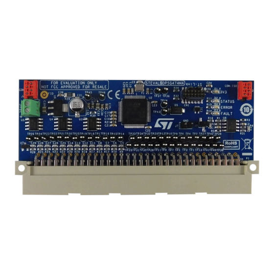
Figure 1.
STEVAL-DPSG474 control board
®
Cortex
to another control board via opto-coupled serial communication
UM2997
User manual
®
M4 32-bit RISC core operating
www.st.com
Advertisement
Table of Contents

Related Manuals for ST STEVAL-DPSG474


Summary of Contents for ST STEVAL-DPSG474
-
Page 1: Figure 1. Steval-Dpsg474 Control Board
UM2997 User manual Getting started with the STEVAL-DPSG474 digital power supply control kit Introduction STEVAL-DPSG474 is a digital power supply control kit. It consists of a main board, based on the STM32G474RE microcontroller from the STM32G4 family, and an adapter board, which provides different communication interfaces and allows programming the microcontroller through a standard 20-pin JTAG connector. -
Page 2: Figure 2. Steval-Dpsg474 Adapter Board
UM2997 Figure 2. STEVAL-DPSG474 adapter board UM2997 - Rev 1 page 2/24... -
Page 3: Features
UM2997 Features Features • Control board for digital SMPS (PFC converters, HF isolating DC-DC converters, DC-AC inverters) based on STM32G474RE microcontroller: – High-resolution timer (HRTIM) for D-SMPS applications – Filter math accelerator unit (FMAC) to perform arithmetic operations on vectors –... -
Page 4: Overview
U1: STM32G474RE 32-bit microcontroller U2: DSMPS standard 64-pin connector for digital power applications U3: STDC14 connector to program and/or debug applications via ST-LINKV3 or to connect the adapter board U4: Supply connector to provide an external 5 V U5: LDO to regulate a 3.3 V to supply MCU... -
Page 5: Dsmps Connector
DSMPS connector DSMPS connector The DSMPS connector is a 64-pin ST standard connector adopted in several power conversion evaluation kits (for example, STEVAL-DPSLLCK1, STEVAL-DPSTPFC1, STEVAL-LLL009V1, etc.), which allows an easy control board connection and a fast microcontroller change. Thanks to this modular approach, you can use the same control board for different applications, or change the microcontroller to evaluate the performances of the latest ST products. -
Page 6: Stdc14 Connector
COMP6_INP STDC14 connector The CN1 connector can be used either to connect a standard ST-LINKV3 dongle, which allows programming the microcontroller and debugging the user application using an SWD connection. It also allows connecting the adapter board included in the STEVAL-DPSG474 kit. -
Page 7: Adapter Board
LEDs The control board embeds three user LEDs that, in ST FW applications, are usually adopted to show the status of the power converter and if any fault occurred. The number of blinks of each LED depends on the final application. - Page 8 UM2997 LEDs Diode Name Color Function Fault LED: it indicates that a nonrecoverable fault occurred (for example, an overcurrent, etc.) FAULT_LED and you have to restart the board. Error LED: it indicates that a recoverable fault occurred (for example, an input undervoltage, ERROR_LED Yellow etc.).
-
Page 9: Getting Started
Step 1. Choose one of the substeps below. Step 1a. Connect the ST-LINKV3 programmer to the STD14 (CN1) connector and connect the USB cable to the PC. Step 1b. Connect the adapter board to the STD14 (CN1) connector to use a programmer with a standard 20-pin JTAG connector, or to use one of the provided communication interfaces (UART, CAN, or SMBUS). -
Page 10: Schematic Diagrams
Schematic diagrams Figure 5. STEVAL-DPSG474 control board: MCU circuit schematic MCU I/O ANALOG INPUTS DSMPS CONNECTOR PINS LEDs STM32G474RET6 +3.3V TP14 PWM SIGNALS ADC12_IN1 ADC12_IN6/COMP3_INM TP15 ADC12_IN1 HRTIM_CHA1/TIM1_CH1 ADC_1/DIFF_ADC_1+ PWM_1 LED GREEN ADC12_IN2/OPAMP1_VINP ADC12_IN7/COMP3_INP HRTIM_CHA2/TIM1_CH2 PWM_2 ADC1_IN3/OPAMP1_VOUT/COMP2_INM 1 of 2... -
Page 11: Figure 6. Steval-Dpsg474 Control Board: D-Smps Connector Circuit Schematic
Figure 6. STEVAL-DPSG474 control board: D-SMPS connector circuit schematic VDD_iso USART_TX_iso USART_RX_iso GND_iso CAN_1_TX/SPI_NSS CAN_1_RX/SPI_SCK SMBus_SCL/UI_USART_RX/CAN_2_RX SMBus_SMBA/SPI_MOSI/EEV_4 SMBus_SDA/UI_USART_TX/CAN_2_TX +3.3V FAULT_1 GPIO_1/GP_PWM_1 PWM_1 PWM_2 PWM_3 PWM_4 PWM_5 PWM_6 PWM_7 PWM_8 PWM_9 PWM_10 PWM_11 PWM_12 GPIO_2/COMP_2_OUT/GP_PWM_2 GPIO_3/COMP_1_OUT/FAULT_2 GPIO_4/EEV_1 GPIO_5/DAC_1 GPIO_6/DAC_2 GPIO_7/DAC_3/OP-AMP_1_OUT GPIO_8/EEV_2... -
Page 12: Figure 7. Steval-Dpsg474 Control Board: Isolated Communication Circuit Schematic
Figure 7. STEVAL-DPSG474 control board: isolated communication circuit schematic VDD_iso UART OPTOCOUPLER VDD_iso +3.3V VDD_iso 0.1uF 0.1uF GND_iso USART_RX_iso USART_RX_iso GND1/K2 MCU_USART_ISO_RX MCU_USART_ISO_RX Vout1 VDD2 USART_TX_iso USART_TX_iso VDD1 Vout2 15pF GND2/K1 15pF ACSL-6210 MCU_USART_ISO_TX MCU_USART_ISO_TX R5 39 GND_iso GND_iso CONNECTION BETWEEN TWO CONTROL BOARDS VDD_iso +3.3V... -
Page 13: Figure 8. Steval-Dpsg474 Adapter Board Circuit Schematic
Figure 8. STEVAL-DPSG474 adapter board circuit schematic USER COMMUNICATION CONFIG SWD USER-COMMUNICATION JTAG SMBUS_SDA +3.3V +3.3V USART_TX +3.3V I2C_SDA/USART_TX/CAN_TX CAN_TX 4.7k JTDI_JTAG_ADP +3.3V JTMS_ADP 0.1uF USART_RX JTCK_ADP JTMS_ADP JTCK_ADP I2C_SCL/USART_RX/CAN_RX JTDO_ADP 4.7k RESET#_BTN I2C_SMBA CAN_RX SMBUS_SCL RESET#_ADP I2C_SCL/USART_RX/CAN_RX I2C_SDA/USART_TX/CAN_TX CON20-JTAG Male Connector 2x10 ST-LInk V3 &... -
Page 14: Bill Of Materials
UM2997 Bill of materials Bill of materials Table 5. STEVAL-DPSG474 bill of materials Item Q.ty Ref. Part/value Description Manufacturer Order code Table 6. STEVAL-DPSG474M Control board Not available for separate sale Table 7. STEVAL-DPSADP02 Adapter board Not available for separate sale Table 6. - Page 15 UM2997 Bill of materials Item Q.ty Ref. Part/value Description Manufacturer Order code CONN FMALE-ON- TE Connectivity COM ISO BRD 4POS VERT 215079-4 AMP Connectors CONN FMALE-ON- TE Connectivity BRD 4POS VERT 215079-4 AMP Connectors CONN JUMPER Sullins Connector Jumper-Female SHORTING 1.27MM NPB02SVAN-RC Solutions GOLD...
- Page 16 0.1uF 50 V ±10% 0603 CAP CER 0.1UF 50V X7R Wurth Electronics 885012206095 C5 C6 (1608 Metric) 0603 Inc. C7 C8 ST-LInk V3 & Adapter CONN HEADER SMD FTSH-107-01-F-DV-K- Samtec Inc. 14POS 1.27MM P-TR RED LED 0603 (1608 LED RED CLEAR 0603 Wurth Electronics...
- Page 17 UM2997 Bill of materials Item Q.ty Ref. Part/value Description Manufacturer Order code 10k 0603 (1608 Metric) RES SMD 10K OHM 1% Yageo RC0603FR-0710KL 0.1W, 1/10W ±1% 1/10W 0603 120R 0603 (1608 Metric) RES SMD 120R OHM 1% Yageo RC0603FR-07120RL 0.1W, 1/10W ±1% 1/10W 0603 0 0603 (1608 Metric) CHIP RESISTOR SMD 1%...
-
Page 18: Kit Versions
STEVAL$DPSG474A schematic diagrams STEVAL$DPSG474A bill of materials 1. This code identifies the STEVAL-DPSG474 evaluation kit first version. It is printed on the board PCB. The kit includes the STEVAL-DPSG474M control board, whose first version is identified by the STEVAL$DPSG474MA code, and the STEVAL-DPSADP02, whose first version is identified by the STEVAL$DPSADP02A code. -
Page 19: Regulatory Compliance Information
UM2997 Regulatory compliance information Regulatory compliance information Formal Notice Required by the U.S. Federal Communications Commission FCC NOTICE This kit is designed to allow: (1) Product developers to evaluate electronic components, circuitry, or software associated with the kit to determine whether to incorporate such items in a finished product and (2) Software developers to write software applications for use with the end product. -
Page 20: Revision History
UM2997 Revision history Table 9. Document revision history Date Revision Changes 12-Apr-2022 Initial release. UM2997 - Rev 1 page 20/24... -
Page 21: Table Of Contents
UM2997 Contents Contents Features................3 Overview . -
Page 22: List Of Tables
STEVAL-DPSG474 bill of materials ........ -
Page 23: List Of Figures
STEVAL-DPSG474 control board: MCU circuit schematic ........ - Page 24 ST’s terms and conditions of sale in place at the time of order acknowledgment. Purchasers are solely responsible for the choice, selection, and use of ST products and ST assumes no liability for application assistance or the design of purchasers’...
Need help?
Do you have a question about the STEVAL-DPSG474 and is the answer not in the manual?
Questions and answers