Sign In
Upload
Manuals
Brands
ST Manuals
Computer Hardware
SL-TTM001V1
ST SL-TTM001V1 Manuals
Manuals and User Guides for ST SL-TTM001V1. We have
1
ST SL-TTM001V1 manual available for free PDF download: User Manual
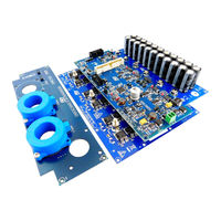
ST SL-TTM001V1 User Manual (42 pages)
5 kW low voltage high current inverter for automotive motor control applications
Brand:
ST
| Category:
Computer Hardware
| Size: 2 MB
Table of Contents
Figure 1. STEVAL-TTM001V1 Evaluation Kit
1
Evaluation Kit Features
2
Electrical and Functional Characteristics
2
Target Applications
2
Safety and Operating Instructions
3
General Terms
3
Intended Use of Evaluation Kit
3
Evaluation Kit Setup
3
Electronic Connections
3
Evaluation Kit Overview
4
Figure 2. STEVAL-TTM001V1 Block Diagram
4
STEVAL-CTM004V1 Power Board
5
STH315N10F7 N-Channel Power MOSFET Characteristics
5
Figure 3. Main Blocks of the STEVAL-CTM004V1 Power Board
5
Figure 4. Package and Internal Schematic Diagram
6
STEVAL-CTM007V1 Driver Board
7
Power Supply Section
7
Bus Voltage Monitoring
7
Temperature Monitor
7
Figure 5. STEVAL-CTM007V1 Driver Board Functional Blocks
7
Table 1. Input Voltage Bus and Input Signal to SPC5 ADC Channel
7
L9907 Gate Driver Characteristics
8
L9907 Supply Voltage Configuration for 48 V Applications
8
Table 2. NTC Electrical Characteristics
8
Bus Link Capacitor Board and Current Sensing Board
9
STEVAL-CTM005V1 Bus Link Capacitor Board
9
STEVAL-CTM008V1 Current Sensing Board
9
Figure 6. STEVAL-CTM005V1 Bus Link Capacitor Board
9
Figure 7. STEVAL-CTM008V1 Current Sensing Board
10
How to Set up the System
11
Connectors
11
Figure 8. Current Sensing Connector (CON2 on Driver Board)
12
Figure 9. 34-Pin Motor Control Connector (J1 on the Driver Board)
12
Table 3. Current Sensing Connector Pinout
12
Signal Leds
13
Push Buttons
13
Table 4. Motor Control Connector Pinout
13
Table 5. LED Indicators on Board
13
Table 6. Push Buttons Descriptions
13
SPC5 Software Development Tools
14
Firmware for SPC560P50L3
14
Table 7. Required Parameters for STEVAL-TTM002V1 Power Stage
14
Experimental Measurements
16
Figure 10. Measured Waveforms
16
Figure 11. Measured Temperatures of U_Phase Power Mosfets
17
Table 8. Measured Case Temperatures of the STH315N10F7 Power Mosfets
17
STEVAL-TTM001V1 Kit Schematic Diagrams
18
Power Board Schematic Diagrams
19
Figure 12. Power Board Schematics
19
Bulk Capacitor Board Schematic Diagrams
20
Figure 13. Capacitor Board Schematics
20
Driver Board Schematic Diagrams
21
Figure 14. Driver Board Schematics - Main with Connectors
21
Figure 15. Driver Board Schematics - Sensing and Status
22
Figure 16. Driver Board Schematics - Gate Driver Section
23
Figure 17. Driver Board Schematics - Overcurrent Protection
24
Figure 18. Driver Board Schematics - Power Supply
25
Current Sensor Board Schematic Diagrams
26
Figure 19. Current Sensor Board Schematics
26
STEVAL-TTM001V1 Bill of Materials
27
Power Board Bill of Materials
27
Table 9. STEVAL-TTM001V1 Evaluation Kit Bill of Materials
27
Table 10. Power Board Bill of Materials
27
Bulk Capacitor Board Bill of Materials
28
Table 11. Capacitor Board Bill of Materials
28
Driver Board Bill of Materials
29
Table 12. Driver Board Bill of Materials
29
Current Sensor Board Bill of Materials
34
Table 13. Current Sensor Board Bill of Materials
34
PCB Layouts
36
Figure 20. STEVAL-CTM004V1 Power Board Layout
36
Revision History
37
Table 14. Document Revision History
37
Advertisement
Advertisement
Related Products
ST SPEAr320
ST STM8/128-EVAL
ST STEVAL-IHM017V1
ST STSW-L9026-Y0
ST STEVAL-TTM001V1
ST STEVAL-ISQ008V1
ST STM32F078CBT6
ST STM32F078CBY6TR
ST STM32MP133C
ST SL-PN-IOD01A1
ST Categories
Motherboard
Computer Hardware
Microcontrollers
Control Unit
Controller
More ST Manuals
Login
Sign In
OR
Sign in with Facebook
Sign in with Google
Upload manual
Upload from disk
Upload from URL