Table of Contents
Advertisement
Quick Links
User manual for ready-to-use evaluation kit based on universal ST25R200 NFC
Introduction
The
STEVAL-25R200SA
is a ready-to-use kit based on the ST25R200 high-performance NFC universal device for contactless
applications.
The kit allows evaluating the ST25R200 features and functionality in the reader/writer modes.
Presented in the form of a single divisible card (STEVAL-25R200A), the kit consists of:
•
The core system designed for basic evaluations of the reader performances and features composed of:
–
ST25R200 module main board that embeds the ST25R200 device and an STM32 G0 processor
–
STLink companion board that includes an ST-LINK in-circuit debugger and programmer for the STM32.
–
Main NFC antenna 20x20 mm etched on the PCB with its tuning circuit.
•
The complementary antennas are designed for testing various topologies that can substitute the main NFC antenna:
–
Dual antenna hub with two 12 x 12 mm tuned antennas for evaluating the ST25R200 dual antenna feature.
–
Flexible antenna board tuned for being connected to the flexible antenna delivered with the kit.
–
50-ohm antenna interface board tuned for being connected to any 50-ohm NFC antenna available on the market.
•
The tag boards for reader and tag system evaluation:
–
Tag 1: ST25TV board that embeds an ST25TV with its tuned 10 x 5 mm antenna
–
Tag 2: ST25TN board that embeds an ST25TN with its tuned 10 x 5 mm antenna
These eight boards are breakable for composing and evaluating various combinations.
A connector is present on all subsystems for a quick and robust connection to the system core. It is based on the ST25R200
and the STM32, which includes hardware and software tools that enable using the entire STM32 ecosystem.
This board is powered through a micro-USB connector.
Thanks to several demonstrations that can be performed, this kit helps the users develop and test their applications.
The board is configured to support ISO14443A/B, and ISO15693 communication.
The
ST25R200
manages frame coding and decoding in reader mode for standard applications, such as NFC, proximity, and
vicinity HF RFID standards. It supports ISO/IEC 14443 type A/B and ISO/IEC 15693 RF communication protocols as well as the
detection, reading and writing of NFC forum type 1, 2, 4, and 5 tags.
It contains a low power wake-up system capable of detecting an approaching tag. It also contains a low power RC Oscillator
and wake-up timer to automatically wake-up the device after a selected time period and check for a tag presence.
The kit is FCC certified, with FCC ID: YCPR200AD1. It is also IC certified, with IC: 8976A-R200AD1; PMN: STEVAL-25R200A;
HVIN: STEVAL-25R200A.
UM3199 - Rev 1 - September 2024
For further information contact your local STMicroelectronics sales office.
device for contactless applications
UM3199
User manual
www.st.com
Advertisement
Table of Contents

Related Manuals for ST ST25R200


Summary of Contents for ST ST25R200
- Page 1 These eight boards are breakable for composing and evaluating various combinations. A connector is present on all subsystems for a quick and robust connection to the system core. It is based on the ST25R200 and the STM32, which includes hardware and software tools that enable using the entire STM32 ecosystem.
-
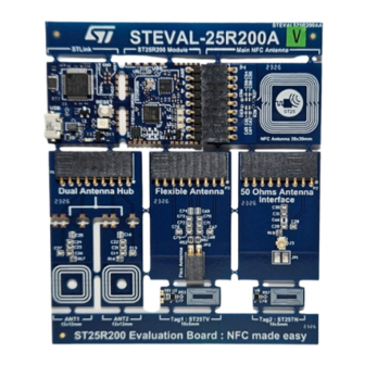
Page 2: Figure 1. Steval-25R200A Top Side
UM3199 Figure 1. STEVAL-25R200A top side Notice: For dedicated assistance, submit a request through our online support portal at www.st.com/support. UM3199 - Rev 1 page 2/34... -
Page 3: Features
• Two tag boards with the chip soldered and the antenna etched on PCB with its associated tuning circuit. • A board dedicated to the ST-LINK in-circuit debugger and programmer for the STM32 • Free comprehensive firmware library compatible with... -
Page 4: Hardware Overview
– The STLink debugger that powers and link the boards through a micro-USB connector to a computer with a graphical user interface running. This firmware is available on ST.com. – The ST25R200 module that embeds an STM32 and the ST25R200. -
Page 5: The Core System
2.2.2 STLink board The STLink is the in-circuit debugger and programmer for the STM32G0 microcontroller located on the ST25R200 module application board. The serial wire debugging (SWD) is the bus interface for this communication. It also provides a Virtual COM port interface allowing the host PC to communicate with the target microcontroller through a UART. -
Page 6: St25R200 Module
ST25R200 module is used separately, other possibilities are offered (Table An LDO converts the voltage applied down to 3.3 V to supply the microcontroller and the ST25R200. A connector allows to plug an antenna. Five antennas are delivered with kit, the main NFC Antenna of 20x25 mm... - Page 7 Description ST25R200 Module V-USB Optional + 5V USB input 5VUSB 5V_USB_CHGR + 5V VDD_STM32 Regulator 3.3V Output Table 4. STLink to ST25R200 module PCB pads Signal Description VCCSTLK Vcc STlink RX UART RX UART G0 TX UART TX UART G0...
-
Page 8: Figure 6. Optional Usb
UM3199 Hardware overview 2.2.3.2 Optional USB The footprint proposed allows soldering a five-pin HE14 connector for many development boards with micro-USB 2.0 available on the market. Figure 6. Optional USB 2.2.3.3 Optional STLink V3 connector The footprint proposed allows soldering a Samtec FTSH-107-01-L-DV-K-A connector for a debug connector with STDC14 available with the STlink-V3 family probe. -
Page 9: Main Nfc Antenna
The dual hub antenna consists of a connector, a PCB hub, and two 12 x 12 mm tuned antennas. Each antenna is etched on a PCB with its tuning circuit for evaluating the ST25R200 dual antenna feature. The three subsystems are breakable with the interfaces between boards accessible through PCB pads, and signals are referenced. -
Page 10: Flexible Antenna
The 50-ohm antenna consists of a connector and a PCB with the tuning circuit and pads for a 50-ohm antenna NOT delivered with the STEVAL kit, but available on the market. The connector allows a direct connection to the main board ST25R200 module to replace the main NFC antenna; the pads are dedicated to the 50-ohm antenna connection. -
Page 11: Antenna Tuning
The tag boards are available for reader&tag system evaluation. The antennas delivered are very small, which can impact the reader plus tag system if the application requires a long range. In this case, please refer to the design recommendations provided on the ST website NFC. 2.5.1 Tag 1: ST25TV This board embeds a ST25TV (ST25TV02K-CAFH3 UFDFPN5) with its tuned 10 x 5mm antenna. -
Page 12: Tag 2: St25Tn
UM3199 Hardware overview Figure 13. ST25TV board 2.5.1.1 Use cases Product Identification, asset tracking, consumer engagement, access control, gaming, tamper proof applications, and brand protection. 2.5.1.2 Key features • ISO15693 and NFC Type V (long range operations, up to 53kb/s) •... - Page 13 UM3199 Hardware overview 2.5.2.3 Key benefits • Tiny FPN5 package (1.7x1.4mm) – Low cost application • 50pF internal RF tuning capacitor allowing small antenna design • 60-year data retention, 100K cycles erase/write UM3199 - Rev 1 page 13/34...
-
Page 14: Kit Contents
(ST25TV512C-AFG9) > Talkin Things PN in TT-HD12-01-S1CL01 ST25TV the STEVAL-25R200SA Kit ST25R200- ST25R200 in piece ST25R200 3x parts in piece of real for tests UQFN24_4X4_0.5 of real in the STEVAL-25R200SA Kit 1. Including boards and accessories 2. Including breakable device... -
Page 15: Naming Location
UM3199 Kit contents Naming location Figure 15. STEVAL-25R200A top side UM3199 - Rev 1 page 15/34... -
Page 16: Figure 16. Steval-25R200A Bottom Side
UM3199 Kit contents Figure 16. STEVAL-25R200A bottom side UM3199 - Rev 1 page 16/34... -
Page 17: Getting Started
• A safety extra-low voltage (SELV) limited power source to supply the unit through the USB port (option 2) • A micro-USB cable to use the embedded ST-LINK and the STM32 ecosystem development How to use the kit Step 1. -
Page 18: Schematic Diagrams
VUSB_MCU GND_USB 100nF VCC_STLK 100nF 100nF VCC_STLK 100nF Staggered Vias 0R NC To restore connections by wire if StLink V2 and ST25R200 Boards are separated 100nF VCC_STLK 5V_USB_CHGR T_NRST PA0/WKUP UART_RX (STLK TX To G0 RX) PA2/USART2_TX PB2/BOOT1 CASTELLATION UART_TX... -
Page 19: Figure 19. Steval-25R200Sa Main Board Circuit Schematic (3 Of 7)
GND_C6_ANT 150pF 2% RFI2_C6_ANT 0402 10pF RFO2_C6_ANT 0402 0402 1R13 33pF 1% RFI2_C6_ANT 10pF 2% 240pF 1% 0402 0402 FROM ST25R200 RFI1_C6_ANT GND_C6_ANT 10pF 2% 240pF 1% RFO1_C6_ANT 0402 0402 0402 0402 1R13 33pF 1% SSW-109-02-G-S-RA ANT1 10pF GND_C6_ANT RFI1_C6_ANT... -
Page 20: Figure 21. Steval-25R200Sa Main Board Circuit Schematic (5 Of 7)
0603 150pF 2% RFI2_Flex_ANT 0603 10pF RFO2_Flex_ANT 0603 0603 560mR 33pF 2% 0603 0603 NOT MOUNTED 360pF 2% Flex Antenna FROM ST25R200 0603 GND_FLEX_ANT SSW-102-02-G-S-RA 0603 NOT MOUNTED 360pF 2% RFO1_Flex_ANT 0603 0603 560mR 33pF 2% SSW-109-02-G-S-RA 0603 10pF GND_FLEX_ANT... -
Page 21: Figure 23. Steval-25R200Sa Main Board Circuit Schematic (7 Of 7)
UM3199 Schematic diagrams Figure 23. STEVAL-25R200SA main board circuit schematic (7 of 7) CASTELLATION SB 0603 Not Mounted 33pF CASTELLATION 0402 0402 ST25TV02KC-TFH3 Not Mounted 6.8pF 0402 0402 ST25TN01KAFH5 UM3199 - Rev 1 page 21/34... -
Page 22: Bill Of Materials
ST25TN01K-AFG5 Provided by CS separate sale Adhesive Tag for ST25TV Not available for ST25TV512C-AFG9 Provided by CS separate sale SAMPLE OF ST25R200 in piece Not available for ST25R200-UQFN24_4X4_0.5 of reel separate sale FIRMWARE of testing for Not available for FIRMWARE... - Page 23 UM3199 Bill of materials Item Q.ty Ref. Part/value Description Manufacturer Order code C14, C26, C29, Capacitor 0603 10pF 50V 5% C68, 10pF, 0603, 50V, +/-2% MURATA GRM1885C1H100GA01D C71, C72, C16, C25, Capacitor 0603 33pF 50V 2% 33pF, 0603, 50V, +/- 2% MURATA GRM1885C1H330GA01J C69,...
- Page 24 UM3199 Bill of materials Item Q.ty Ref. Part/value Description Manufacturer Order code C80, 5.6pF, 0201, 25V, +/- Capacitor 0201 5.6pF 25V MURATA GRM0335C1E5R6DA01D 0.5pF Voltage suppressor 1610-2PINS-A-K ESDA7P60-1U1M ESDA7P60-1U1M DIODE BAT60JFILM (not D2, D3 SOD323 BAT60JFILM mounted) ESD PROTECT TRANSIL D6, D7 0201 ESDALC6V1-1U2 ESDALC6V1-1U2...
- Page 25 UM3199 Bill of materials Item Q.ty Ref. Part/value Description Manufacturer Order code R15, 0201 Resistor 0201 (not mounted) R39, 36K, 0201 Resistor 0201 36K 1% 50 mW VISHAY CRCW020136K0FKED 1K5, 0201 Resistor 0201 1K5 1% 50mW YAGEO AC0201FR-071K5L RESISTOR 0201 2K7 1% 2K7, 0201 YAGEO RC0201FR-072K7L...
- Page 26 ST25TV02KC-TFH3 TFH3 UFDFPN5 SOT23-5PINS LDO LD3985M33R SOT23-5 LD3985M33R DFN6-3x3 LDO LDO40LPU33RY DFN6 LDO40LPU33RY ESD PROTECTION QFN-8L ECMF02-4CMX8 (not mounted) HF READER ST25R200- QFN24 ST25R200-BMET BMET QFN24 MCU STM32G0B1KEU6N UFQFPN32 STM32G0B1KEU6N UFQFPN32 NFC TAG IC ST25TN01K- UFDFPN5 ST25TN01K-AFH5 AFH5 UFDFPN5 CRYSTAL NX2016SA-27.12MHZ-...
-
Page 27: Kit Versions
UM3199 Kit versions Kit versions Table 8. STEVAL-25R200SA versions PCB version Schematic diagrams Bill of materials STEVAL$25R200SAA schematic diagrams STEVAL$25R200SAA bill of materials STEVAL$25R200SAA 1. This code identifies the STEVAL-25R200SA evaluation kit first version. The kit consists of a STEVAL-25R200A whose version is identified by the code STEVAL$25R200AA and a STEVAL-FANTR1A whose version is identified by the code STV$FANTR1AA. -
Page 28: Regulatory Compliance Information
UM3199 Regulatory compliance information Regulatory compliance information Note: The evaluation kit with order code STEVAL-25R200SA contains the main board STEVAL$25R200AA plus the flexible antenna board STEVAL$FANTR1AA. FCC certified, with FCC ID: YCPR200AD1 IC certified, with IC: 8976A-R200AD1; PMN: STEVAL-25R200SA; HVIN: STEVAL-25R200SA Notice for US Federal Communication Commission (FCC) STEVAL-25R200SA Part 15.19... - Page 29 UM3199 Regulatory compliance information Notice for the United Kingdom The kit STEVAL-25R200SA is in compliance with the UK Radio Equipment Regulations 2017 (UK SI 2017 No. 1206 and amendments) and with the Restriction of the Use of Certain Hazardous Substances in Electrical and Electronic Equipment Regulations 2012 (UK SI 2012 No.
-
Page 30: Revision History
UM3199 Revision history Table 9. Document revision history Date Version Changes 30-Sep-2024 Initial release. UM3199 - Rev 1 page 30/34... -
Page 31: Table Of Contents
ST25R200 module ........ - Page 32 ST25R200 module top and bottom side ........
-
Page 33: List Of Tables
STLink to ST25R200 module........ - Page 34 ST’s terms and conditions of sale in place at the time of order acknowledgment. Purchasers are solely responsible for the choice, selection, and use of ST products and ST assumes no liability for application assistance or the design of purchasers’...
Need help?
Do you have a question about the ST25R200 and is the answer not in the manual?
Questions and answers