Table of Contents
Advertisement
Quick Links
Advertisement
Table of Contents

Related Manuals for Mahr Maxum III


Summary of Contents for Mahr Maxum III
- Page 1 Instruction Manual Maxum III Digital Indicator Document Part No. 2239028 Rev. D...
- Page 2 Models Part No. Short Part No. Stem Stem Length Range Long Range Description Diameter mm / inch 2033101 2033102** 0.375” 17mm / 0.670” 2033103 2033104 0.375” 38mm / 01.50” No output 2033105 2033106 17mm / 0.670” 2033107 2033108 38mm / 1.50” 2033111 2033112** 0.375”...
-
Page 3: Table Of Contents
2.1 Maxum III Features ........ - Page 4 4.1 Operating the Maxum III ........
- Page 5 4.2.1.1 How to change between the Standard Mode and the Enhanced Mode: ..28 4.2.2 Enhanced/Dynamic Mode ............28 4.2.2.1 Minimum Reading .
- Page 6 5.4.1 Resetting Digital Gain ............35 6.0 Parts and Service .
- Page 7 8.2.2 Operation ..............51 8.2.3 Sleep Mode/Over range .
-
Page 8: Precautions And General Information
Digital Transducers: ments. When placed in the Enhanced Mode, the Maxum III pro- Any Maxum III Indicating Unit can be used with any Maxum III vides the capability of measuring relative maximum, minimum Digital Transducer. Make sure the transducer connector is prop- and T.I.R. -
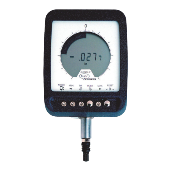
Page 9: Product Features
There are two selections for digital resolution with each Digital Figure 1 Range selection (see below): 2.0 PRODUCT FEATURES Digital Range Available Resolutions 2.1 Maxum III Features 0.0005” or 0.0001” / ±0.100 inch / ±1.99 mm 0.005 mm or 0.001mm Switchable Inch / Metric Units 0.0005” or 0.0001” / ±0.040 inch / ±1.0 mm... -
Page 10: Maxum Iii Features
The Short Range Maxum III unit is capable of selecting two dig- OPTION: The Sleep Mode may be disabled as a factory option ital ranges. The Short Range model can select between ±0.040 when requested at time of order. However, when using bat- and ±0.199 in (±1.00 and ±0.199 mm) ranges. - Page 11 Transducer Range Calibration Lockout (Option) Maxum III Remote Indicating Units auto-sense the type of Digi- Allows the entry into the calibration mode via an access key tal Transducer plugged into it. There are two types of Digital (Order No. 2240545 - 6 pin, Order No. 2240547 -10 pin) when Transducers that are auto-sensed;...
- Page 12 Left Tolerance Right Tolerance Limit Limit There are two ratios available for the Maxum III indicator. All standard models come with a 1:1 ratio meaning 0.010 inch True Spindle Auto Zero movement of the spindle results in 0.010inch reading on the Position indicators digital display.
-
Page 13: Controls - Standard Mode
2.1.2 Controls - Enhanced Mode Left Tolerance Limit Sets the left arrow at desired limit. Display Switches Hold Indexes the digital readout and analog display clockwise (right- handed switch) or counterclockwise (left-hand switch). The dis- play switches will function only when the Indicator or Indicating Unit is in the Auto-Zero (gaging) mode. -
Page 14: Setup Mode
The Maxum III uses the two mushroom push-buttons to enter Setup Mode, make feature selections, and exit Setup Mode. A quick reference sheet of but-... -
Page 15: Entering Setup Mode
Maxum III setup menu is provided at the Once in the Setup Mode simply press the corresponding button end of the manual ’9.0 Quick Step Flow Chart’ on page 55. to toggle through the features and choices. The RESET button... -
Page 16: Exiting Setup Mode
3.2 Changing inch / metric units 1. Enter setup mode. 2. Press the RESET button until the letter u indicates the unit’s setup feature. Figure 6 - Shown in Inch Units 3.3 Changing Measuring Direction 1. Enter Setup Mode 2. Press the RESET button until the letter d shows in the Figure 5 - Shown in Millimeter Units last digital position of the LCD display. -
Page 17: Changing Measuring Direction
measuring range to another. Only Short Range Models have this selection available. Figure 7 - Shown in Reverse Polarity Direction 3. Press the HOLD button to toggle between Normal (n) and Reverse (r) direction. Notice the tolerance arrows Figure 8 also indicate the direction change. -
Page 18: Changing Digital Resolution
Figure 10 Figure 9 4. Press the HOLD button to toggle between standard digital resolution and high digital resolution selections. 3.5 Changing Digital Resolution Resolution selections are dependent on indicator model 1. Enter Setup Mode. and digital range selection (see, ‘Overlay Selection Table’ on page 20). -
Page 19: Selecting Analog Fan Scale/ Overlay
Figure 11 3.6 Selecting Analog Fan Scale/ Overlay Figure 12 Notice the fan display toggles between half full scale (only half 3.6.1 Setting-up the Indicator Analog Fan Scale the LCD fan segments are on) and full scale (all the LCD fan 1. -
Page 20: Installing And Removing The Overlay Scale
3.7 Installing and Removing the Overlay Scale Once the pushbutton settings have been set, if desired, install the corresponding overlay onto the front of the Maxum III per table, Overlay Selection Table’ on page 20. The following is a recommended procedure for installing and removing the over- lay from the front of the Maxum III indicator. -
Page 21: Installation
Overlay Selection Table 3.7.1 Installation green side of the overlay and metric (mm) uses the yel- low side of the overlay. 1. Chose the correct color and overlay scale from the table above (Overlay Selection Table’). Inch readout uses the Maxuum III Digital Electronic Indicator 2239028 Rev D... -
Page 22: Removal
2. Remove protective sheets from the overlay. Take the overlay and place one side of the long edge under the lip of the housing. Figure 15 - Unit shown with yellow metric overlay 3.7.2 Removal NOTE: This is a recommended removal process and not neces- Figure 14 - Unit shown without overlay sarily the only method of removing the overlay. - Page 23 3. Simply pull-up on the tape to remove the overlay. with the sticking portion facing down. Refer to Figure 4. Carefully remove the tape from the overlay and discard 2. Place the bottom sticking portion of the tape onto the the tape.
-
Page 24: Selecting Data Output Format
3.8 Selecting Data Output Format 3. Press the HOLD button to toggle through the following selections: 1. Enter setup mode 2. Press the RESET button until the letter o shows in the Standard classic Maxum output format Digimatic/BCD output format last digital position of the LCD display. -
Page 25: Operation
This assures that the Maxum III Indicator is operational. The in/mm icon also appears when the unit is active. A Maxum III Indicator can be mounted in a gage or fixture using an optionally available back., or the Indicator can be stem- mounted. -
Page 26: Standard Mode
segment. Enhanced functions using the FAN display (MIN, MAX normal static Fan display and no tolerance arrows when within and TIR) require the user to depress the RESET button after tolerance. If out of tolerance one of the arrows will be flashing. obtaining an on-scale reading. -
Page 27: Setting Upper And Lower Tolerance Limits
(-) set point. NOTE: Some Mahr gages are furnished with separate instruc- 2. Press and release the Left Tolerance Limit tions covering their use with Maxum III Indicators. Refer to button. those instructions for specific steps for setup and operations. -
Page 28: Reapportioning Measuring Range
Displays a static real-time representation of the gaging contact movement. The Maxum III allows the resetting of the dynamic reading to 1. Press and release True Spindle Position button. enable the start of a measurement cycle and to HOLD the cur- rent reading for Display Value capture. -
Page 29: How To Change Between The Standard Mode And The Enhanced Mode
4.2.1.1 How to change between the Standard Mode 4.2.2 Enhanced/Dynamic Mode and the Enhanced Mode: The unit has to be in the Enhanced/Actual Mode in order to enter into the full Enhanced Mode. While in Enhanced/Actual a NOTE: The following steps require the unit to be on-scale. On- press and release of the min, TIR, Hold, or Max button enters scale means that a digital reading is viewed on the digital dis- into its corresponding selection. -
Page 30: Total Indicated Reading
4.2.2.5 Reset reading from full scale MIN to the MAX value. Use the RESET button to clear the displayed Maximum value and start a new Resets the Dynamic Function for its next measurement. Max measurement. In the Dynamic Function, this button is used to reset the 4.2.2.3 Total Indicated Reading Dynamic Measurement and sets the indicator to start the next measurement. -
Page 31: Changing The Battery
5.1.1 Changing the Battery The screws are design to push the door away from the case allowing an easy grip for removing the door. 5.1.1.1 Disassembly 2. Once the screws are completely unthreaded, carefully 1. Place Indicator or Indicating Unit face down on a clean lift the battery door off the rear case (Figure 20-B). -
Page 32: Reassembly
NOTE: Whenever the battery is removed and replaced, the Indicator or Indicating Unit will lose its previous zero setting. NOTE: Maxum III indicators do not need to have the rear case removed and doing so will void the warranty. 5.2 Checking Accuracy Accuracy is checked at zero, both ends of the digital range, and approx. - Page 33 2. Using the Indicator's Standard Mode, Press and release the True Spindle Position button to enter the TSP mode. 3. Adjust the stand until the digital readout reads exactly zero. Do not use Auto-Zero. 4. Remove the Zero block and place each of the other gage blocks under the measuring spindle.
- Page 34 I I II D D igital G G age Blocks R R eading A A llowable Variation in Digital M M ax m m R R ange t t o Use s s hould be* R R eading M M odel 0.101in -0.01900 0.110in...
-
Page 35: Cleaning The Spindle
1. Unscrew the Contact Point. Use soft jaw pliers, or pro- 5.3.1 Contact Points tect the Contact Point with a soft cloth. Maxum III Indicator and Digital Transducer models having an 0.375 in / 9,5 mm diameter stem can use any regular 4-48 2. Carefully remove the Boot. -
Page 36: Resetting Digital Gain
The reverse fan display indicates the digital POT position. If NOTE: Auto Zero must not be used when calibrating. Any off- needed, the POT may be reset to its center position by a press set due to the use of Auto Zero, will be reflected in calibration and release of the zero reset button accuracy. -
Page 37: Parts And Service
6.0 Parts and Service ** NOTE: Indicates factory calibrated range (75% of Full Scale). Maxum III Indicator parts and service are available from Mahr Inc., Providence, RI, U.S.A. Contact your Mahr Federal represen- tative in Providence. Carefully pack items to prevent damage in shipment. -
Page 38: Replacement Parts
For 8mm dia. Stem 6 mm long, radiused tip, M2.5 thread EPT-1037-W2 For 8mm dia. Stem 6 mm long, radiused tip, M2.5 thread-for use with Lifting Lever Many alternate Contact Points are available. Refer to the Mahr Precision Gages catalog. Maxuum III Digital Electronic Indicator 2239028 Rev D... - Page 39 Indicator Parts ECS-1214 Dust Cap for Output Connector (1) Battery Door Assembly – (complete assembly recommended for purchase) 2239034 Seal for battery door cover (1) 2239003 2239010 Battery door (1) 2239001 Screw, Battery Door (2) {requires special tool for assembly} 2239002 Speed-Nut, Battery Door (2) {requires special tool for assembly} ERG-1046...
- Page 40 Spindle Assembly Parts Maxuum III Digital Electronic Indicator 2239028 Rev D...
-
Page 41: Accessories
6.2 Accessories Description Mahr Part # Remote Foot Switch (Hold/Reset) EAS-2868 (10pin output models) Remote Hand Switch (Hold/Reset) EAS-2867 (10pin output models) 2239040 Overlay Kit (includes all 3 overlays below) 5-0-5 Overlay 2239052 25-0-25 Overlay 2239053 50-0-50 2239054 Access Key (6pin output) -
Page 42: Specifications
7.0 Specifications MODELS: LONG RANGE SHORT RANGE Digital Range: Standard Range 0.100 in / 1 99 mm 0.040 in / 1 00 mm Reduced Range None 0.0199 in / 0 199 mm Digital Resolution 0.0001 in / 0 001 mm 0.00002 in / 0 0005 mm (switchable^) 0.0005 in / 0 005 mm... -
Page 43: Output Information
Three outputs are avail- a plus/minus signal, has allowed for communication to virtually able on the Maxum III Indicator. The output to be used by the all data collection devices. Because of the remote HOLD and operator is selectable in one of three formats: RESET features we offer two connector configurations. -
Page 44: Power Inputs
Signal Com (Gnd) Shield Shield 8.1.1 Power Inputs Not for customer The Maxum III normally runs on battery. When the output con- use*** nection is attached, a 5 volt and ground connection powers the Not for customer Maxum III output circuitry. -
Page 45: Hardwired
(+) or high (-) for 0.4 ms before and 4.0 ms after the digital start pulse. The digital line (start pulse) and clock are used as the main indicators for data input. The Maxum III has the buffered signals available at the output connector. - Page 46 Maxum III Enhanced Mode (Cont.) A1 P1 (all segments connected) Bit Position Data X - see Table 1 Start pulse X - see Table 1 X - see Table 1 B2 (b2 c2 connected) A2 (a2, d2, e2, f2 connected)
-
Page 47: Signal Input
The Maxum III serial output bits 23, 24, and 25 marked with an ments. In this manner, the unit can be made to freeze the last ‘X’ is not used. However, for Maxum III Enhanced Mode use the set of readings: table on page 46. - Page 48 The assertion signal is a momentary logic ’O’ (GND) of at least 100 ms duration. INOTE: In the Standard Mode, grounding the input causes the unit to display the quantity ‘O’ in both the analog and digital displays. This input is an external zeroing control. As with nor- mal operation unit must be on-scale for it to zero the gage.
- Page 49 Clock Stops ~1.8 ms after last bit Sign is valid ~1.8 ms after last data bit Maxuum III Digital Electronic Indicator 2239028 Rev D...
-
Page 50: Ascii Output
Data is transferred at 2400 6-pin conn. 10-pin conn. baud and is updated 16 times a second. Maxum III models use a 6-pin or 10-pin connector and feature a SERIAL OUTPUT Clock Out Clock Out capability. -
Page 51: Protocol
8.2.1 Protocol NOTE: When using serial output cable 2239036 or 2239038 Protocol for com setting is 8-N-1 9600 Baud. 1start bit 2 stop bits 7 bits ASCII character 2400 baud The character strings will be in one of the following formats: No parity bits <SP>... -
Page 52: Operation
TTL loads. RESET HOLD 8.2.5 Power Input The Maxum III requires a regulated +5V D.C. and GROUND input to power the output circuitry. Maxuum III Digital Electronic Indicator 2239028 Rev D... -
Page 53: Theory Of Operation
8.4 Theory of Operation 8.4.1.1 Timing Diagram for Digimatic Data Transfer Method Enabling the data request line (SREQ\, pin # 4) will activate data transmission. The SREQ\ input is falling edge triggered and TIMING DIAGRAM FOR DIGIMATIC DATA TRANSFER METHOD active low, it must go from high to low and held low until data transmission starts, then it can be brought high. -
Page 54: Bcd Encoded Data Format
All BCD digit fields will be set to 'F'. The sign, decimal point, and unit fields are encoded normally. 8.4.2 Electrical Characteristics There are two types of hardware data communications signals associated with the Maxum III Digimatic output, one is the input Maxuum III Digital Electronic Indicator 2239028 Rev D... -
Page 55: Quick Step Flow Chart
9.0 Quick Step Flow Chart Maxuum III Digital Electronic Indicator 2239028 Rev D... - Page 56 Copyright © 2018 Mahr Inc. All rights reserved. Due to technical improvements and/or further product developments, all of the specifications shown in this document are subject to change without notice. Other product and company names listed are trademarks or trade names of their respective companies.