Table of Contents
Advertisement
Advertisement
Table of Contents

Related Manuals for Mahr Pocket Surf IV


Summary of Contents for Mahr Pocket Surf IV
- Page 1 Instructions ® Pocket Surf Portable Surface Roughness Gages...
- Page 2 Note: U.S. Patent No. 4,776,212 ® ® Pocket Surf is a registered trademark of Mahr Federal Inc. ® Mahr Federal Inc. 2000...
- Page 3 Measuring Ranges....R — 1 " to 250 "/0.03 m to 6.35 m — 8 " to 999 "/0.2 m to 25.3 m — 8 " to 999 "/0.2 m to 25.3 m —...
- Page 4 Roughness Average — the arithmetic average height of roughness irregularities measured from a mean line within the evaluation length (L). MEAN LINE Maximum Roughness Height — the largest of the 5 maximum peak-to-valley roughness depths in 5 successive sampling lengths. In the illustration below, R (DIN) = R Mean Peak to Valley Height —...
- Page 5 (continued) Maximum Roughness Depth — For the Evaluation Length equaling one cutoff, it is the vertical distance between the highest peak and the deepest valley within the sampling length. For the Evaluation Length equaling 3 cutoffs, it is the largest of the 3 maximum peak-to-valley roughness depths in 3 successive sampling lengths.
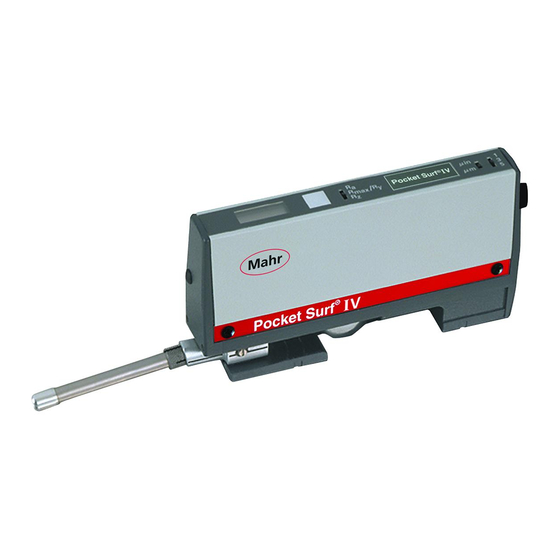
- Page 6 1 Digital Display 2 “Start” Button 3 Parameter Selection Switch 4 Output Connector 5 Battery Compartment Cover 6 2 “V” Feet (on bottom of unit) 7 Probe Holding Block 8 Probe 9 Protective Cover 10 Inch/Metric Switch 11 Traverse Length Switch...
- Page 7 1. Remove Protective Cover 9 from Pocket Surf base and slide Battery Compartment Cover 5 off end of Pocket Surf unit. 2. Install/replace battery and replace Battery Compartment Cover. 3. Press and release “Start” button to check battery condition (see next section). ®...
- Page 8 (continued) In addition to displaying the measured roughness value, the digital readout also sig- nals other conditions: 2. Immediately after pressing and releasing the “Start” button, the readout should display the “Battery” icon and “all 8’s” (full display), indicating satisfactory battery condition for normal operation. The display shows the reading for about seven seconds.
- Page 9 There are three traverse lengths available. For measuring short surfaces such as o-ring grooves, short lands and shoulders, use Switch Positions 1 or 3. .075"/2.0mm .030"/0.8mm .135"/3.5mm .090"/2.4mm .195"/5.0mm .150"/4.0mm Cutoff equals .030"/0.8mm. The Pocket Surf gage will operate in any one of four different probe positions (see illustration on next page).
- Page 10 The Pocket Surf gage can be hand held or placed on a surface in any attitude; it will operate in virtually any position — horizontally, vertically, at any angle in between, even upside-down. In the “Closed” probe position, the gage can ¼"/6.35mm in diameter.
- Page 11 To use the gage in the other probe positions — 90°, 180° or 270°, the Pocket Surf unit and probe must be carefully aligned to the workpiece surface to be measured. The base of the Pocket Surf unit must be at approximately the (within ±.100"/±2,5mm) as the surface being measured, and the axis of probe traverse must be to the surface being measured.
- Page 12 In the 180° “Extended” position, the surfaces, large cylindrical or O.D. surfaces and inside diameters. Because there is some leeway permitted in the elevation between the base of the Pocket Surf unit and the surface to be measured, the gage can be used to measure sur- faces that are raised slightly above or recessed slightly below (within Be sure the two “V’s”...
- Page 13 The Pocket Surf gage is calibrated 1. To elevate the Pocket Surf base to using the Reference Specimen and the the same height as the surface of EPL-1681 Riser Plate supplied with the the Reference Specimen, place the Pocket Surf Kit. Pocket Surf unit on the Riser Plate so that the two “V’s”...
- Page 14 (continued) If the reading is within ±4 in/±0.1 m specimen. Continue pressing the Start of the value stated on the label on the Button to change the number in the bottom of the specimen*, calibration display until the same number as the Is within tolerance.
- Page 15 (normally furnished) — For most surface roughness applications. 90° conical diamond stylus – 0.0004"/10 m radius for EGH-1019, 0.0002"/5 m radius for EGH-1026.† EGH-1020-W1 (optional) — For gaging sharp edges or small O.D.’s where the probe moves parallel to the axis of traverse. 90°...
- Page 16 (continued) EGH-1028 (optional) — For measuring the bottoms of “O” ring grooves, recesses and holes to depths of ¼"/6.35mm. Also used for short lands and shoulders. 90° conical diamond stylus—0.0004"/10 m radius. The Groove Bottom Probe can only be used in the 180° “Extended” position with the Pocket Surf unit supported 1.
- Page 17 The EAS 2421 Vee Fixture is used for probe in its 90° position, to measuring cylindrical (O.D.) parts up to approximately 1"/25mm in diameter that are the captive screw in the Top too small to be accommodated in the gage’s Plate.
- Page 18 For accurate measurement with the Vee Fixture, the axis of the Vee must be aligned parallel to the axis of probe be repositioned with a little effort. traverse and at the proper distance 2. Place the 1/8"/3.2mm diameter Setting from the Pocket Surf unit so that the Pin, PS-145, in the Vee and proceed probe skid and stylus travel precisely to measure it like a regular workpiece...
- Page 19 (continued) 5. Place the Setting Pin back in the the Vee so that the probe skid Vee and place the Top Plate (with the and stylus travel precisely along Pocket Surf unit) back on the Bottom the top (“crown” or “high spot”) Plate, with the probe skid and stylus rest- of the Setting Pin throughout the en- ing on the top of the Setting Pin.
- Page 20 “Extended” or 270° positions. The stand’s 360° Column Clamp and Bracket can be The EAS 2426 Universal Stand positioned anywhere vertically and radially on the column, permitting the stand to be position comparator stand for staging the Pocket Surf unit in any position used as a height stand on a surface plate or other suitable work surface to measure relative to the workpiece surface to...
- Page 21 (cont’d) 1. Mount the Pocket Surf unit in the bracket on the Stand using the captive The EAS-2567 Column Clamp & screw in the base of the bracket. The Bracket is the same Column Clamp screw mates with the tapped hole in and Bracket assembly furnished the bottom of the Pocket Surf housing.
- Page 22 2. Position the Height Stand so that the probe is above the workpiece sur- The EAS-2496 Height Stand is in- face to be measured. Use the Coarse tended to be used on a surface plate or skid and stylus barely in contact with workpiece surfaces ranging in height make the black, scribed Reference Line face to a maximum height of approxi-...
- Page 23 cylindrical workpieces from When measuring workpiece sur- ¼"/6.35mm diameter up to faces with the Pocket Surf probe 1½"/38mm long — long enough to span in the “Closed” position, the EAS- the slot lengthwise and sit securely in 2584 Bottom Plate will accom- the “V”...
- Page 24 Gently brush the ruby skid and diamond stylus tip to remove any foreign matter. To protect the gage when not in use, Clean the brush well in denatured alcohol always return the probe to its “Closed” and repeat the cleaning process until all position and replace the Protective contamination has been removed.
- Page 25 (continued) To remedy these conditions: — Motor did not start. 1. Make sure the workpiece is clean and dry, and the surface to be measured is — Motor failed to accelerate to free from gross defects. proper operating speed. 2. Make sure the gage and workpiece —...
- Page 26 If none of the above remedies work, and an error message persists — particularly “E1” 4. Clean the bearing slot beneath the or “E4”, contact Mahr Federal Inc. Ser- Probe Mounting Block. vice Department for assistance and repair 5. Replace the battery. Alkaline batter- information.