Table of Contents
Advertisement
Quick Links
Download this manual
See also:
User Manual
Advertisement
Table of Contents

Related Manuals for Multitech MultiVOIP 800 MVP800


Summary of Contents for Multitech MultiVOIP 800 MVP800
- Page 1 Standalone Voice/IP Gateway Model MVP800 Proprietary Mode Quick Start Guide...
-
Page 2: Quick Start Guide
Furthermore, Multi-Tech Systems, Inc. reserves the right to revise this publication and to make changes from time to time in the content hereof without obligation of Multi-Tech Systems, Inc. to notify any person or organization of such revisions or changes. -
Page 3: Table Of Contents
Contents Introduction ... 4 Related Documentation ... 4 Installing Your MultiVOIP ... 5 Configure and Install your Host MultiVOIP ... 5 Configure your Client MultiVOIPs ... 6 Deploy the VOIP Network ... 6 Unpacking Your MultiVOIP ... 7 Safety Warnings ... 8 Cabling Your MultiVOIP ... -
Page 4: Introduction
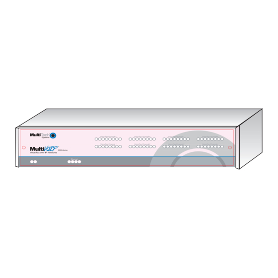
MultiVOIP Quick Start Guide Introduction Welcome to Multi-Tech's new standalone Voice/IP Gateways, which allow analog voice and fax communication over an IP network. The MultiVOIP model number MVP800 has eight voice/fax channels. Multi-Tech’s new voice/fax over IP gateway technology allows voice and fax communication to ride, with no additional expense, over your existing IP network, which has traditionally been data-only. -
Page 5: Installing Your Multivoip
Adobe Acrobat Reader loaded on your system. The MultiVOIP User Guide is also available on Multi- Tech’s Web site at http://www.multitech.com. From the Multi-Tech homepage, click Support | Manuals | MultiVOIP and choose the appropriate User Guide to download the .pdf file. -
Page 6: Configure Your Client Multivoips
MultiVOIP Quick Start Guide configures the unit and builds the Phone Directory Database that will reside in the Host unit. Configure your Client MultiVOIPs The next step is to configure the MultiVOIPs designated as “Client” units. The Client units can be another MVP800 or MVP400 unit or a MultiVOIP 200 Series. -
Page 7: Unpacking Your Multivoip
If the battery fails, the board must be sent back to Multi-Tech Sytems for battery replacement. The E&M, FXS, and Ethernet ports are not designed to be connected to a Public Telecommunication Network. -
Page 8: Cabling Your Multivoip
MultiVOIP Quick Start Guide Cabling Your MultiVOIP Cabling your MultiVOIP involves connecting the host MultiVOIP to your LAN and telephone equipment. If you are connecting any Voice/Fax Channel to an E&M trunk other than type 2, perform the E&M Jumper Block Positioning procedure, which immediately follows the Cabling Procedure, before performing the Cabling Procedure. - Page 9 3. Connect a network cable to the ETHERNET 10BASET connector on the back of the MultiVOIP. Connect the other end of the cable to your network. 4. If you are connecting a station device such as an analog telephone, a fax machine, or a Key Telephone System (KTS) to your MultiVOIP, connect one end of an RJ11 phone cord to the Voice/Fax Channel 1 FXS connector on the back of the MultiVOIP and the other end to the station...
-
Page 10: E&M Jumper Block Positioning Procedure
MultiVOIP Quick Start Guide E&M Jumper Block Positioning Procedure A jumper block exists for each voice/fax channel. The jumper block is to the right of each set of channel jacks. The jumper block contains 8-pairs of pins. The jumper plug fits over three pairs of pins on the jumper block. - Page 11 Phillips quarter-turn screws and replace the four Phillips screws on the back and the four Phillips screws on the bottom. 8. If you are using a Magix 400 E&M Tie Card, connect the ground pin to the chassis ground screw as shown. 9.
-
Page 12: Configuring Your Host Multivoip
2. Insert the MultiVOIP 800 System CD into your CD-ROM drive. The CD should start automatically. It may take 10 to 20 seconds for the Multi-Tech CD installation window to display. Q.931 Signaling, Ch2 [902] Q.931 Signaling, Ch4 [906]... - Page 13 If the Multi-Tech Installation CD window does not display automatically, click My Computer, then right click the CD ROM drive icon, click Open, and then click the Autorun icon. 3. When the Multi-Tech Installation CD dialog box displays, click the Install Software icon.
- Page 14 MultiVOIP Quick Start Guide Click Next to continue. 5. Follow the on-screen instructions to install your MultiVOIP software. You may choose the Destination Location of your MultiVOIP software or you can choose to select the default destination by clicking Next. If you click Browse, you can choose from several folders.
- Page 15 Click OK to continue. 7. The Setup Complete dialog displays. Click Finish to continue. 8. The following message displays: Click Yes to continue. 9. The IP Protocol Default Setup dialog box displays. The default Frame Type is TYPE_II. If this does not match your IP network, change the Frame Type by clicking the drop down box.
- Page 16 MultiVOIP Quick Start Guide 10. In the Ethernet group, enter the IP Address, Subnet Mask, and Gateway Address, unique to your IP LAN. The IP address is your unique LAN IP address, and the Gateway address is the IP address of the device connected to the Internet/Intranet.
- Page 17 Software Installation panel of the MultiVOIP. If you are connecting a station device such as an analog telephone, a fax machine, or a Key Telephone System (KTS) to the Voice/Fax connector on the back of the unit, FXS (Loop Start) will most likely be the correct Interface option most of the time .
- Page 18 MultiVOIP Quick Start Guide dialing a phone number. The default setting is 5. In the Inter Digit Time box, enter the maximum amount of time in milliseconds that the unit will wait before mapping the dialed digits to an entry in the Phone Directory Database. If too much time elapses between digits and the wrong numbers are mapped, you hear a rapid busy signal.
- Page 19 channel’s configuration to any other channel by clicking Copy. Everything on the Interface tab will be copied to the other channel. 13. Repeat the above steps to configure the interface type for each voice/fax channel. The Voice/Fax tab displays the parameters for the voice coder, faxing, and DTMF gain.
- Page 20 MultiVOIP Quick Start Guide Note: Only change the DTMF gain under the direction of Multi-Tech Technical Support. 16. The Fax group enables you to send and receive faxes on the selected voice/fax channel. You can select the maximum baud rate for faxes from the list in the Fax group.
- Page 21 19. The Call Authentication option enables password protection for outbound and inbound calls on the selected voice/fax channel. If you enable password protection on inbound or outbound calls, you need to also enter a password of up to 14 numeric characters in the Password box.
- Page 22 MultiVOIP Quick Start Guide following steps. The MultiVOIP configured as a “Host” will contain the host database. The host database has the phone numbers of all the MultiVOIP’s available for communication on an IP network. This database is downloaded to each Client MultiVOIP as it comes online.
- Page 23 25. The Description is optional, but can be useful in associating the channel to the extension. If you want, enter a description of your local phone number. This description identifies the phone number you entered in the previous step. 26. The Permit Hunting option lets the answering MultiVOIP roll over to its second channel if the first channel is busy.
- Page 24 MultiVOIP Quick Start Guide 28. Click OK and you are returned to the Phone Directory Database dialog box, which now includes phone number 101 with its IP address, channel number, and description. 29. Click Add and the Add/Edit Phone Entry dialog box displays again.
- Page 25 31. Enter a description for the remote MultiVOIP phone number for Channel 1 in the Description box. Note: If the remote MultiVOIP is located behind a proxy server that uses a dynamically assigned IP address, select Dynamic (disabling Static IP Address) and leave the IP Address box blank.
- Page 26 MultiVOIP Quick Start Guide Note: If only Channel 1 is active, you must enter two phone numbers. The first number is the local MultiVOIP phone number for Channel 1, and the second number is the remote MultiVOIP phone number for Channel 1. 34.
-
Page 27: Configuring Your Client Multivoips
38. Windows 3.1 users - you are returned to your Program Manager where the MultiVOIP Program Group and Program Item (Windows icons) have been created. Windows 95/98/NT/2000 users - you are returned to your desktop. Configuring Your Client MultiVOIPs The client MultiVOIPs can be another MVP800 or MVP400 unit or a MultiVOIP 200-series. - Page 28 MultiVOIP Quick Start Guide 1. Disconnect the pc from the command port of the Host MultiVOIP and connect it to the command port on the Client MultiVOIP. 2. Windows 3.1 users - from the Program Manager, double- click the MultiVOIP Configuration icon in the MultiVOIP Program Group.
- Page 29 4. In the Port Address group, enter the IP Address and IP Mask. In the Gateway Address group, enter the gateway IP address for the client unit. The IP address is your unique LAN IP address, and the Gateway address is the IP address of the device connected to the Internet/Intranet.
- Page 30 MultiVOIP Quick Start Guide If you are connecting a station device such as an analog telephone, a fax machine, or a Key Telephone System (KTS) to the Voice/Fax connector on the back of the unit, FXS (Loop Start) will likely be the correct Interface option most of the time.
- Page 31 in milliseconds that the unit will wait before mapping the dialed digits to an entry in the Phone Directory Database. If too much time elapses between digits and the wrong numbers are mapped, you hear a rapid busy signal. If this happens, hang up and dial again.
- Page 32 DTMF tone pair. Make your selections from the lists in the DTMF Gain group. In the Duration box, enter the DTMF tone duration in milliseconds. 100 is entered by default. Note: Only change the DTMF gain under the direction of Multi-Tech Technical Support.
- Page 33 10. The Fax group enables you to send and receive faxes on the selected voice/fax channel. You can select the maximum baud rate for faxes from the list in the Fax group. If you do not plan to send or receive faxes on a given voice/fax channel, you can disable faxes in the Fax group.
- Page 34 MultiVOIP Quick Start Guide 13. The Call Authentication option enables password protection for outbound and inbound calls on the selected voice/fax channel. If you enable password protection on inbound or outbound calls, you need to also enter a password of up to 14 numeric characters in the Password box.
- Page 35 16. Click OK after the download is complete. Click Start | Programs| MultiVOIP 800 v. 301E | MultiVOIP Configuration. At the main menu, click Phone Book to display the Phone Directory Database dialog box. In the Database Type group, click the Client option. The Host IP Address box becomes active.
- Page 36 MultiVOIP Quick Start Guide 18. Click OK and you are returned to the main menu. 19. Click Download Setup to write the new configuration to the client unit. The Save Setup dialog displays. 20. Select the Save Current Setup as User Default Configuration check box, then click OK.
-
Page 37: Deploying The Voip Network
Deploying the VOIP Network Deploying the VOIP network involves the VOIP Administrator developing the VOIP Dialing Directory and deploying the preconfigured client MultiVOIPs to their remote sites. The remote site administrators need only connect power to the preconfigured MultiVOIP, connect it to their Ethernet LAN and predefined telephone equipment, and then wait for the phone directory database to be downloaded. - Page 38 MultiVOIP Quick Start Guide Remote Site Administrator 3. Unpack your MultiVOIP. 4. Connect one end of the power supply to a live AC outlet and connect the other end to the Power connection on your MultiVOIP. Voice/Fax Channel Connections E&M FXO FXS E&M PSTN Figure 5.
- Page 39 on the back of the MultiVOIP and the other end to the trunk phone jack. Refer to the MultiVOIP User Guide for E&M pin assignments. 7. Repeat the above step to connect the remaining telephone equipment to each Voice/Fax Channel on your MultiVOIP. 8.
-
Page 40: Limited Warranty
MultiVOIP Quick Start Guide Limited Warranty Multi-Tech Systems, Inc. (“MTS”) warrants that its products will be free from defects in material or workmanship for a period of two years from the date of purchase, or if proof of purchase is not provided, two years from date of shipment. -
Page 41: Contacting Technical Support
Contacting Technical Support Country By E-mail France: support@multitech.fr India: support@multitechindia.com U.K.: support@multitech.co.uk U.S. & Canada: support@multitech.com Rest of World: support@multitech.com Internet: http://www.multitech.com/support Please have your product information available, including model and serial number. FCC Declaration NOTE: This equipment has been tested and found to comply with the limits for a Class A digital device, pursuant to Part 15 of the FCC Rules. - Page 42 MultiVOIP Quick Start Guide...
Need help?
Do you have a question about the MultiVOIP 800 MVP800 and is the answer not in the manual?
Questions and answers