Multitech MVP400 User Manual
Standalone voice/ip gateway
Hide thumbs
Also See for MVP400:
- Quick start manual (64 pages) ,
- User manual (99 pages) ,
- Install manual (2 pages)
Table of Contents
Advertisement
Quick Links
Advertisement
Table of Contents

Subscribe to Our Youtube Channel
Related Manuals for Multitech MVP400


Summary of Contents for Multitech MVP400
- Page 1 Standalone Voice/IP Gateway Models MVP400 and MVP 800 User Guide...
- Page 2 User Guide 88310600 Revision A MultiVOIP400 (Model MVP400) and MultiVOIP 800 (Model MVP 800) This publication may not be reproduced, in whole or in part, without prior expressed written permission from Multi- Tech Systems, Inc. All rights reserved. Copyright © 1999, by Multi-Tech Systems, Inc.
-
Page 3: Table Of Contents
Contents Chapter 1 - Introduction and Description Introduction ..............................6 Preview of this Guide ..........................6 MultiVOIP Application ..........................8 Front Panel Description ..........................11 Back Panel Description ..........................12 Power Connector ..........................12 Command Port Connector ......................... 12 10Base-T (Ethernet) Connector ......................12 VOICE/FAX CHANNEL _ ........................ - Page 4 Chapter 5 - Remote Configuration and Management Introduction .............................. 54 Remote Configuration ..........................54 Modem-Based ........................... 54 LAN-Based ............................56 Remote Management ..........................58 Telnet ..............................58 WEB Management ..........................60 Chapter 6 - Warranty, Service and Tech Support Introduction .............................. 62 Limited Warranty ............................
-
Page 5: Chapter 1 - Introduction And Description
Chapter 1 - Introduction and Description... -
Page 6: Introduction
Once configured, the MultiVOIP then allows voice and fax to travel down the same path as your traditional data communications. The MVP400 is designed with four voice/fax channels (which offer three voice/fax interfaces per channel), a 10M bps Ethernet LAN interface, and a command port for configuration. The MVP800 is designed with eight voice/fax channels, 10M bps Ethernet LAN interface, and command port. - Page 7 Chapter 1 - Introduction and Description Chapter 5 - Remote Configuration and Management Chapter 5 provides procedures for changing the configuration of a remote MultiVOIP. Remote configuration allows you to change the configuration of a unit by simply connecting two modems between the two MultiVOIPs and remotely controlling the unit.
-
Page 8: Multivoip Application
MultiVOIP User Guide MultiVOIP Application A typical Voice Over IP (VOIP) network is shown in Figure 1-2 with a headquarters site and three remote sites (Sales office, regional and marketing offices). This typical Voice Over IP network can be set up via the Internet or your Intranet. The headquarters site is set up with a 4-channel MultiVOIP (MVP 400) connected to the headquarters LAN and four voice/fax channels connected to the in- house telephone switch (PBX). - Page 9 Chapter 1 - Introduction and Description Phone Directory Data Base Number Description Channel IP Address Headquarters 201.23.122.118 Trunk Ext 4 Headquarters 201.23.122.118 Trunk Ext 5 Headquarters 201.23.122.118 Trunk Ext 6 Headquarters 201.23.122.118 Trunk Ext 7 Sales 205.24.123.119 KTS 201 Sales 205.24.123.119 PSTN 202 Regional...
- Page 10 MultiVOIP User Guide Using the same example as above, but calling the Regional office. A person at headquarters would pick up a telephone and dial say trunk extension 5. This connects channel 2 of the headquarters MultiVOIP. A second dial tone is heard, then you would dial say 301. The telephone connected to channel 1 of the Regional office MultiVOIP rings and your voice conservation takes place.
-
Page 11: Front Panel Description
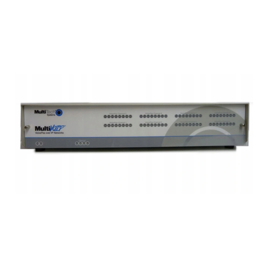
Chapter 1 - Introduction and Description Front Panel Description The front panel contains three groups of LEDs that provide the status of the Ethernet connection, Voice/Fax channels, and general status of the MultiVOIP. The front panel is shown in Figure 1-3, and a description of each LED follows. -
Page 12: Back Panel Description
MultiVOIP User Guide Back Panel Description The cable connections for the MultiVOIP are made at the back panel. Connectors include Power, Command Port (RS232), Ethernet (10BASE-T), Voice/Fax Channels (E&M, FXO and FXS). The cable connectors are shown in Figure 1-4 and defined in the following groups. Figure 1-4. -
Page 13: Specifications
Chapter 1 - Introduction and Description Specifications • One 1 Meg by 32 byte at 70 nanosecond SIMM is 4 Mb DRAM Caution: SIMM speed and size cannot be mixed • Two Meg of flash memory Ethernet Port • Single Ethernet Interface - 10Base-T (twisted pair) keyed RJ-45 connector. Command Port •... - Page 14 MultiVOIP User Guide...
-
Page 15: Chapter 2 - Installation
Chapter 2 - Installation... -
Page 16: Installing Your Multivoip
MultiVOIP User Guide Installing Your MultiVOIP The basic steps of installing your MultiVOIP network involve unpacking the units, connecting the cables, and configuring the units using the included management software (MultiVOIP Configuration). The recommended installation process includes three phases that, when completed, result in a fully functional Voice Over IP network. -
Page 17: Unpacking Your Multivoip
Chapter 2 - Installation Unpacking Your MultiVOIP Remove all items from the box. Figure 2-1. Unpacking Safety Warnings Caution Danger of explosion if battery is incorrectly replaced. A lithium battery on the voice/fax channel board provides backup power for the time keeping capability. -
Page 18: Phase 1: Cabling Procedure
MultiVOIP User Guide Phase 1: Cabling Procedure Phase 1 cabling involves connecting the master MultiVOIP to your LAN and telephone equipment. If you are connecting any Voice/Fax Channel to an E&M trunk other than type 2, perform the E&M Jumper Block Positioning procedure before connecting power to the unit. Connect one end of the power supply to a live AC outlet and connect the other end to the MultiVOIP as shown in Figure 2-2. -
Page 19: E&M Jumper Block Positioning Procedure
Chapter 2 - Installation E&M Jumper Block Positioning Procedure A jumper block exists for each voice/fax channel. The jumper block is to the right of each set of channel jacks. The jumper block contains 8-pairs of pins. The jumper plug fits over three pairs of pins on the jumper block. - Page 20 MultiVOIP User Guide...
-
Page 21: Chapter 3 - Software Loading And Configuration
Chapter 3 - Software Loading and Configuration... -
Page 22: Phase 1: Configuring Your Master Multivoip
MultiVOIP User Guide Phase 1: Configuring Your Master MultiVOIP The following software loading procedure does not provide every screen or option in the loading process. The assumption is that a technical person is doing the installation and that a thorough knowledge of Windows and the software loading process is understood. - Page 23 Chapter 3 - Software Loading and Configuration Follow the on-screen instructions to install your MultiVOIP software. You may choose the Destination Location of your MultiVOIP software or you can choose to select the default destination by clicking Next. If you click Browse, you can choose from several folders. It is recommended to choose the default destination.
- Page 24 MultiVOIP User Guide The Default Setup dialog box is displayed. Click YES to continue. The IP Protocol Default Setup dialog box is displayed. The default Frame Type is TYPE_II. If this does not match your IP network, change the Frame Type by clicking on the drop down box.
- Page 25 Chapter 3 - Software Loading and Configuration If your station device uses ground start, then chose FXS (Ground Start) option. Refer to the device’s user documentation. If you are using an extension from your PBX, then chose FXO option. Check with your in- house telephone personnel to verify connection type.
- Page 26 MultiVOIP User Guide If you selected the FXO interface and are using touchtone dialing, you can set up the DTMF gain (or output level in decibels - dB) for the higher and lower frequency groups of the DTMF tone pair. Make your selections in the drop-down lists in the DTMF Gain group. Note: Only change the DTMF gain under the direction of Multi-Tech Technical Support supervision.
- Page 27 Chapter 3 - Software Loading and Configuration The Phone Directory Database dialog box is displayed. You will build your personalized VOIP Phone Directory Database in the following steps. A MultiVOIP configured as a Master will contain the master data base. The master database ties the VOIP Phone Number to the IP address of the MultiVOIP and to the Voice/Fax Channel on the MultiVOIP.
- Page 28 MultiVOIP User Guide want to enter in the Ethernet Node ID field. Click OK and you are returned to the Phone Directory Database dialog box, which now includes phone number 101 with its IP address, channel number and description. Click Add (+) and the Add/Edit Phone Entry dialog box is displayed again. Enter the phone number for the remote MultiVOIP in the Station Information group Phone Number field.
- Page 29 Chapter 3 - Software Loading and Configuration Click OK and you are returned to the Phone Directory Database dialog box, which now includes the second number and related information in the Phone Number list. Note: If only Channel 1 is active, you must enter two phone numbers. The first number will be the local MultiVOIP phone number for Channel 1, and the second number will be the remote MultiVOIP phone number for Channel 1.
- Page 30 MultiVOIP User Guide Check to ensure that the BTG LED on the MultiVOIP is Off after the download is complete. This may take several minutes as the MultiVOIP reboots. Win3.1 users - you are returned to your Program Manager where the MultiVOIP Program Group and Program Item (Windows icons) have been created.
-
Page 31: Phase 2: Configure Your Slave Multivoips
Chapter 3 - Software Loading and Configuration Phase 2: Configure Your Slave MultiVOIPs The slave MultiVOIPs can be another MVP 400 or MVP 800 unit or a MultiVOIP-series. If your slave MultiVOIP is an MVP 400 or MVP 800, perform the following software loading procedure. - Page 32 MultiVOIP User Guide The IP Setup dialog box is displayed. The default Frame Type is TYPE_II. If this does not match your IP network, change the Frame Type by clicking on the drop down box. The Frame Type choices are TYPE_II and SNAP. In the Port Address group, enter the IP Address and IP Mask.
- Page 33 Chapter 3 - Software Loading and Configuration If you are using an extension from your PBX, then chose FXO option. Check with your in- house telephone personnel to verify connection type. If you chose an FXO interface, then the Dialing Options Regeneration group is enabled. Check with your local in-house telephone personnel to verify whether your local PBX dial signaling is Pulse or tone (DTMF).
- Page 34 MultiVOIP User Guide To change the voice coder, first select the channel by clicking the Select Channel down arrow and highlighting the channel number, then click the Voice Coder down arrow and highlight your new voice coder entry. If you changed the voice coder, ensure that the same voice coder is used on the voice/fax channel you are calling;...
- Page 35 Chapter 3 - Software Loading and Configuration To change the Tone Pairs on the Regional tab, click the Country/Region down arrow and highlight your specific country or region. The Tone Pairs group parameters change per your choice. Click OK and you are returned to the main menu.
- Page 36 MultiVOIP User Guide Select (check) Save Current Setup as the User Default Configuration, then click OK. The Writing Setup dialog box is displayed as the setup configuration is written to the MultVOIP. After the setup is written to the MultiVOIP, the unit reboots. Check that the BTG LED on the MultiVOIP is Off after the download is complete.
-
Page 37: Phase 3: Deploy The Voip Network
Chapter 3 - Software Loading and Configuration Phase 3: Deploy the VOIP Network Phase 3 involves the VOIP Administrator developing the VOIP Dialing Directory and deploying the preconfigured slave MultiVOIPs to their remote sites. The remote site administrators need only connect power to the preconfigured MultiVOIP, connect it to their Ethernet LAN and predefined telephone equipment, and then wait for the phone directory database to be down loaded. - Page 38 MultiVOIP User Guide If you are connecting the station side of a telephone switch (PBX) to your MultiVOIP, connect one end of an RJ11 phone cord to the Voice/Fax Channel 1 FXO connector on the back of the MultiVOIP and the other end to the phone jack. If you are connecting an E&M trunk from a telephone switch to your MultiVOIP, connect one end of an RJ45 phone cord to the Voice/Fax Channel 1 E&M connector on the back of the MultiVOIP and the other end to the trunk.
-
Page 39: Chapter 4 - Multivoip Software
Chapter 4 - MultiVOIP Software... -
Page 40: Introduction
MultiVOIP User Guide Introduction This chapter describes the MultiVOIP software with the intent to show you how to make changes to the configuration of your MultiVOIP. The major configuration parameters were established during the loading of the software (Chapter 3), and the MultiVOIP software and configuration utilities allow you to make changes to that initial configuration. -
Page 41: Multivoip Configuration
Chapter 4 - MultiVOIP Software MultiVOIP Configuration The MultiVOIP Setup menu consists of 10 buttons in which you can point and click, an Events window in the middle of the menu, and a status bar at the bottom of the menu. The 10 buttons allow you to display and change the voice channels and IP protocol parameters, display and manage the Phone Book listing, define the output of the MultiVOIP, view statistics and call progress, and change features such as SNMP Agent, Telnet Server, WEB Server, and assign a MultiVOIP password. -
Page 42: Changing Channel Parameters
MultiVOIP User Guide Changing Channel Parameters The channel parameters include the interface type and its options, voice and fax settings, and voice communications for the region of the world that the MultiVOIP resides in. The Channel Setup dialog box is accessed from the Main MultiVOIP menu. The Channel Setup dialog boxes contain three tabs that partition the channels into three categories, i.e., interface, voice/fax, and regional. -
Page 43: Voice/Fax
Chapter 4 - MultiVOIP Software are unsure of the correct selection, contact the personnel in charge of your PBX or your local telephone company to determine whether pulse or DTMF should be used. E&M Interface The E&M Interface is used to connect PBX E&M trunks. You will need to select between Dial Tone or Wink signaling and also between 2-wire and 4-wire mode. -
Page 44: Regional
-4 dB and -7 dB, respectively. DTMF Gain should not be changed except under supervision of MultiTech’s Technical Support. Billing Options can be used to track the cost of Inbound and/or Outbound calls on any of the three interfaces (FXO, FXS, or E&M). -
Page 45: Changing The Phone Directory Database
Chapter 4 - MultiVOIP Software Changing the Phone Directory Database The Phone Directory Database dialog box displays all the phone numbers in your MultiVOIP network. The database displays the phone numbers in numerical order with the IP Address, Channel assignment, and Description. Access this database by clicking the Phone Book button on the Main MultiVOIP menu. - Page 46 MultiVOIP User Guide connection and the Proxy Server is using dynamic addressing (i.e., the ISP is assigning the Proxy Server IP address), then this slave MultiVOIP will be defined as using Dynamic addressing and the IP Address field in the Identified By group will grey out (be inactive). If a Proxy Server with a static IP address is in front of the slave MultiVOIP, then the Identified By IP Address field must contain the address of the Proxy Server.
-
Page 47: Changing Ip Parameters
Chapter 4 - MultiVOIP Software Changing IP Parameters The IP Setup dialog box establishes the IP addressing for the local Ethernet LAN, defines the Internet gateway address, and if a proxy server is used to connect a LAN to the Internet, global-to-local IP address translation is required. - Page 48 MultiVOIP User Guide MultiVOIP located behind a Proxy Server at the static IP address. This static IP address will be used in the Phone Directory Database when assigning directory numbers to this MultiVOIP. The Global IP Address field must contain the static IP address of the WAN port of the Proxy Server. The Local IP Address field must contain the local IP address of the MultiVOIP.
-
Page 49: Viewing Statistics
Chapter 4 - MultiVOIP Software Viewing Statistics The Statistics dialog box enables you to view statistics for major events of the MultiVOIP operation. This dialog box is accessed by clicking on the Statistics button on the Main MultiVOIP menu. Statistics can be a helpful troubleshooting tool. For example, viewing the Voice Channel statistics you can see the attempted and completed calls, call duration, average call length, bytes/packets send and received, etc. -
Page 50: Snmp Statistics
MultiVOIP User Guide For the most part these statistics are informational, and their use as a troubleshooting tool will be contingent on the applications running in the upper layers. For example, if you were having problems connecting to the MultiVOIP’s web server, you would look under the TCP section to see if any connections are being established. -
Page 51: Others Setup
Chapter 4 - MultiVOIP Software Others Setup Clicking the Others button on the main menu displays the Others Setup dialog box. This dialog box lets you to enable SNMP Agent (the default is disabled) and set up all the necessary parameters; enable or disable various remote configuration methods such as TFTP (Trivial File Transfer Protocol) Server, Web Server, Dumb Terminal, and Telnet Server;... -
Page 52: Viewing Call Progress
MultiVOIP User Guide Viewing Call Progress The Call Progress dialog box displays the status of a call in progress. This dialog box is accessed from the MultiVOIP Setup menu by clicking on the Call Progress button. The ratio of Packets Lost versus Packets Received provides a general indication of the integrity of the Internet connection. -
Page 53: Chapter 5 - Remote Configuration And Management
Chapter 5 - Remote Configuration and Management... -
Page 54: Introduction
MultiVOIP User Guide Introduction This chapter provides procedures for viewing or changing the configuration of a remote unit. Two methods are provided to access a remote unit; the first method is modem based and the second method is using IP. Within the IP method, three applications can be used: 1) LAN-Based using TFTP (Trivial lFile Transfer Protocol), 2)Telnet as a client application, or 3) a standard web browser on the Internet. - Page 55 Chapter 5 - Remote Configuration and Management Verify that the Communication Type is set for COM Port and the Select Port field is set for the COM port of your local PC. In the Dial String field, enter the AT command for dialing (ATDT) plus the phone number of the remote MultiVOIP.
-
Page 56: Lan-Based
MultiVOIP User Guide LAN-Based The LAN-based remote configuration requires a Windows Sockets compliant TCP/IP stack. TCP/IP protocol software must be installed and functional before the configuration program can be used. You must assign an Internet (IP) address for the PC and for each node that will be managed by the configuration program. - Page 57 Chapter 5 - Remote Configuration and Management and field within a dialog box. After you have changed the configuration of the remote MultiVOIP, click Download Setup to update the configuration. The remote MultiVOIP will be brought down, the new configuration written to the unit, and the unit will reboot.
-
Page 58: Remote Management
MultiVOIP User Guide Remote Management This section describes typical client applications that can be used to configure the MultiVOIP remotely. It is important to note that although any subsequent changes to configuration can be made using these applications, the initial setup and configuration of the MultiVOIP must be done on the local PC, using the MultiVOIP software provided with your unit. - Page 59 Chapter 5 - Remote Configuration and Management MultiVOIP Telnet Server Menu The MultiVOIP Telnet Server menu provides three basic options: Voice over IP Configuration, Phone Directory Database, and Phone Directory Configuration. A further option enables you to close the Telnet session. Voice over IP Configuration Selecting Option 1 displays the main menu, which allows further configuration options.
-
Page 60: Web Management
MultiVOIP User Guide WEB Management The MultiVOIP can be accessed, via a standard Web browser, from anywhere on the connected Internet. In order to provide this support, the WEB Server option has to be enabled from the Others button in the main menu which displays the Applications Setup dialog box (see Chapter 4 - MultiVOIP Software). -
Page 61: Chapter 6 - Warranty, Service And Tech Support
Chapter 6 - Warranty, Service and Tech Support... -
Page 62: Introduction
Defective products must be returned by Customer to MTS’s factory transportation prepaid. MTS WILL NOT BE LIABLE FOR CONSEQUENTIAL DAMAGES AND UNDER NO CIRCUMSTANCES WILL ITS LIABILITY EXCEED THE PURCHASE PRICE FOR DEFECTIVE PRODUCTS. On-line Warranty Registration To register your MultiVOIP on-line, click on the following link: http://www.multitech.com/register... -
Page 63: Tech Support
Use the space below to note the MultiVOIP status: ________________________________________________________________________________________________________ ________________________________________________________________________________________________________ ________________________________________________________________________________________________________ ________________________________________________________________________________________________________ ______________________________________________________________________________________________________________ ______________________________________________________________________________________________________ ______________________________________________________________________________________________________________ ______________________________________________________________________________________________________ Contacting Tech Support via E-mail If you prefer to receive service on-line, via the internet, you can contact Tech Support via e-mail at the following address: http://www.multitech.com/_forms/email_tech_support.htm... -
Page 64: Service
MultiVOIP User Guide Service If your tech support specialist decides that service is required, your MultiVOIP may be sent (freight prepaid) to our factory. Return shipping charges will be paid by Multi-Tech Systems. Include the following with your MultiVOIP: • a description of the problem. -
Page 65: About The Internet
To exit the BBS, type G and press ENTER. About the Internet Multi-Tech is a commercial user on the Internet, and we retrieve messages from our customers on a periodic basis. Multi-Tech’s presence includes a Web site at: http://www.multitech.com and an ftp site at: ftp://ftp.multitech.com... - Page 66 MultiVOIP User Guide...
-
Page 67: Appendixes
Appendixes... -
Page 68: Appendix A - Tcp/Ip (Transmission Control Protocol/Internet Protocol) Description
First, choose a domain name for your company. A domain name is the unique Internet name, usually the name of your business, that identifies your company. For example, Multi-Tech’s domain name is multitech.com ( .com indicates this is a commercial organization; .edu denotes educational organizations, .gov denotes government organizations). Next, determine how many IP addresses you’ll need. - Page 69 Appendix A - TCP/IP Description response, are better suited to the datagram service of UDP because there is no time lost to virtual circuit establishment and termination. UDP’s primary function is to add a port number to the IP address to provide a socket for the application. The Application Layer protocols are examples of common TCP/IP applications and utilities, which include: •...
- Page 70 You first choose a domain name for your company. A domain name is the unique Internet name, usually the name of your business, that identifies your company. For example, Multi-Tech’s domain name is multitech.com (where .com indicates this is a commercial organization; .edu denotes educational organizations, .gov denotes government organizations). Next, you determine how many IP addresses you’ll need.
-
Page 71: Appendix B - Cabling Diagrams
Appendix B - Cabling Diagrams Appendix B - Cabling Diagrams Command Port Cable 21 20 LAN Cable Circuit Signal Name TD+ Data Transmit Positive TD- Data Transmit Negative RD+ Data Receive Positive RD- Data Receive Negative Voice/Fax Channel Connectors Pin Connections E&M Description Description... -
Page 72: Appendix C - Regulatory Information
MultiVOIP 200 User Guide Appendix C - Regulatory Information Class A Statement FCC Part 15 NOTE: This equipment has been tested and found to comply with the limits for a Class A digital device, pursuant to Part 15 of the FCC Rules. These limits are designed to provide reasonable protection against harmful interference when the equipment is operated in a commercial environment. -
Page 73: Canadian Limitations Notice
7. No repairs are to be made by you. Repairs are to be made only by Multi-Tech Systems or its licensees. Unauthorized repairs void registration and warranty. 8. Manufacturer: Multi-Tech Systems, Inc. Trade name: MultiVOIP Model Numbers: MVP400, MVP800 FCC Registration Number: AU7USA-26050-DV-N REN: 0.2A Modular Jack (USOC): RJ-11C or RJ-11W Service Center in U.S.A.:... -
Page 74: Emc, Safety And Terminal Directive Compliance
MultiVOIP 200 User Guide appropriate electric inspection authority, or electrician, as appropriate. EMC, Safety and Terminal Directive Compliance The CE mark is affixed to this product to confirm compliance with the following European Community Directives: Council Directive 89/336/EEC of 3 May 1989 on the approximation of the laws of Member States relating to electromagnetic compatibility. -
Page 75: Glossary
Glossary... - Page 76 MultiVOIP User Guide Access: The T1 line element made up of two pairs of wire that the telephone company brings to the customer premises. The Access portion ends with a connection at the local telco (LEC or RBOC). Accunet Spectrum of Digital Services (ASDS): The AT&T 56K bps leased (private) line service. Similar to services of MCI and Sprint. ASDS is available in nx56/64K bps, where n=1, 2, 4, 6, 8, 12.
- Page 77 Glossary Bell Operating Companies (BOC): The family of corporations created during the divestiture of AT&T. BOCs are independent companies which service a specific region of the US. Also called Regional Bell Operating Companies (RBOCs). Bell Pub 41450: The Bell publication defining requirements for data format conversion, line conditioning, and termination for direct DDS connection.
- Page 78 MultiVOIP User Guide Circuit switching: The temporary connection of two or more communications channels using a fixed, non-shareable path through the network. Users have full use of the circuit until the connection is terminated. Clear Channel: A transmission path where the full bandwidth is used (i.e., no bandwidth needed for signaling, carrier framing or control bits).
- Page 79 Glossary Digital Loopback: A technique used for testing the circuitry of a communications device. Can be initiated locally, or remotely (via a telecommunications device). The tested device decodes and encodes a received test message, then echoes the message back. The results are compared with the original message to determine if corruption occurred en route.
- Page 80 MultiVOIP User Guide Extended Super Frame (ESF): One of two popular formats for framing bits on a T1 line. ESF framing has a 24-frame super-frame, where robbed bit signaling is inserted in the LSB (bit 8 of the DS-0 byte) of frames 6, 12, 18 and 24. ESF has more T1 error measurement capabili- ties than D4 framing.
- Page 81 Glossary Handshaking: A process that two modems go through at the time of call setup to establish synchronization over the data communications link. It is a synchronization and negotiation process accomplished by the exchange of predefined, mutually recognized control codes. High-level Data Link Control (HDLC): An ISO standard, bit-oriented data communications protocol that provides nearly error-free data transfers.
- Page 82 MultiVOIP User Guide Line Coding: The representation of 1s and 0s on a T1 line. The two methods of line coding commonly used, B8ZS and AMI, differ in the restrictions placed on user data. T1 line coding ensures that sufficient timing information is sent with the digital signal to ensure recovery of all the bits at the far end.
- Page 83 Glossary NAK (Negative Acknowledgment): Communications code used to indicate that a message was not properly received, or that a terminal does not wish to transmit. Contrast with ACK. Network: A group of computers connected by cables or other means and using software that enables them to share equipment, such as printers and disk drives to exchange information.
- Page 84 MultiVOIP User Guide Primitive: An abstract representation of interaction across the access points indicating that information is being passed between the service user and the service provider. The OSI Reference Model defines four types of primitives: Request, Indication, Response and Confirm. Private Branch Exchange (PBX): A telephone exchange located on the customer's premises.
- Page 85 Glossary RS232-C: An EIA standard for a serial interface between computers and peripheral devices (modem, mouse, etc.). It uses a 25-pin DB-25, or a 9-pin DB-9 connector. The RS-232 standard defines the purposes, electrical characteristics and timing of the signals for each of the 25 lines.
- Page 86 MultiVOIP User Guide T1: A digital transmission link capable of 1.544M bps. T1 uses two pairs of normal UTP, and can handle 24 voice conversations, each digitized at 64K bps. T1 is a standard for digital transmission in the U.S., Canada, Japan and Hong Kong. T1 is the access method for high- speed services such as ATM, frame relay, and SMDS.
- Page 87 Glossary V.25bis: An ITU-T standard for synchronous communications between a mainframe or host and a modem using HDLC or other character- oriented protocol. V.54: The ITU-T standard for local and remote loopback tests in modems, DCEs and DTEs. The four basic tests are: •...
-
Page 88: Index
MultiVOIP User Guide Limited Warranty ........... 64 Index On-line Warranty Registration ....... 64 Archie ..............71 Ping ............... 71 POP ............... 71 Back Panel ............12 Power Connector ............12 Proxy Server Configuration ......41, 62 ProxyServer Software ........... 40 Collision ..............
Need help?
Do you have a question about the MVP400 and is the answer not in the manual?
Questions and answers