Table of Contents
Advertisement
Simply Engineered Better
October, 2003
P.O. Box 4183
Winston-Salem, North Carolina 27115-4183
Moyer Diebel, U.S.
336/661-1992
Fax: 336/661-1979
Technical Manual
Pass-Through
Glasswasher
Machine Serial No.
P/N
Manual
2674 N. Service Road
Jordan Station, Ontario, Canada L0R 1S0
Model
SW400M5
SW600M5
0507496
REV. F
Moyer Diebel, Ltd.
905/562-4195
Fax: 905/562-4618
Advertisement
Table of Contents

Related Manuals for Moyer Diebel SW-400


Summary of Contents for Moyer Diebel SW-400
- Page 1 Simply Engineered Better October, 2003 P.O. Box 4183 Winston-Salem, North Carolina 27115-4183 Moyer Diebel, U.S. 336/661-1992 Fax: 336/661-1979 Technical Manual Pass-Through Glasswasher Model SW400M5 SW600M5 Machine Serial No. 0507496 Manual 2674 N. Service Road Jordan Station, Ontario, Canada L0R 1S0 Moyer Diebel, Ltd.
- Page 2 Complete the information below so it will be available for quick reference. Model Number __________________________ Voltage and Phase ______________________________________________________________ Moyer Diebel Parts Distributor _______________________________ (if applicable) _____________________________________________________________________________ Moyer Diebel Service Agency ________________________________ _____________________________________________________________________________ Moyer Diebel Service: Moyer Diebel Limited Phone: 1-905-562-4195 1-800-263-5798 Fax: 1-905-562-4618...
-
Page 3: Revision History
Revision History Revision Revised Serial Number Date Pages Effectivity 02/18/91 5181 10/12/94 6106 05/10/95 6216 06/07/95 — 6226 02/02/97 6679 02/28/00 06/18/00 G2182 06/18/01 10/13/03 Comments Issued manual and service parts list, Revision A Tank switch shuts down machine, revised the schematic Changed to new style chemical injection board, revised the schematic... - Page 4 THIS PAGE INTENTIONALLY LEFT BLANK...
-
Page 5: Table Of Contents
WARRANTY ... INTRODUCTION... INSTALLATION... Unpacking ... Measurements ... Utility Locations ... Electrical Connections... Plumbing Connections... Water Connections... Drain Connections ... OPERATION... General ... To Fill The Wash Tank ... Operating Instructions ... Approximate Chemical Settings... 10 Plumbing Diagram... 12 MAINTENANCE... 13 Daily Cleaning Instructions ... -
Page 6: Limited Warranty
WARRANTY Champion Industries/Moyer Diebel Limited, P.O. Box 4183, Winston-Salem, North Carolina 27115, and P. O. Box 301, 2674 North Service Road, Jordan Station, Ontario, Canada L0R 1S0 warrants machines, and parts, as set out below. Warranty of Machines: Champion Industries/Moyer Diebel Limited warrants all new machines of its manufacture bearing the name “Champion”... -
Page 7: Introduction
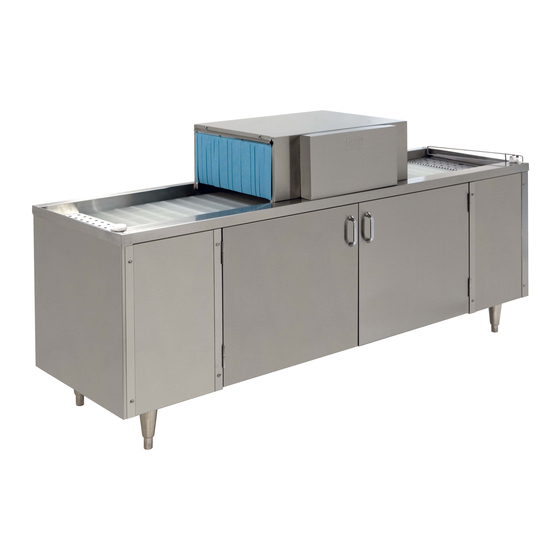
INTRODUCTION Welcome to Moyer Diebel... and thank you for allowing us to take care of your glass washing needs. This manual covers the Models SW400M5 and SW600M5 glasswashers. Your machine was completely assembled, inspected, and thoroughly tested at our factory before it was shipped to your installation site. -
Page 8: Installation
INSTALLATION INSTALLATION Unpacking Remove all packing from inside and on top of the machine. Remove all packing from glass operated switch and left and right pick-up plates. Check that the left and right hand pick-up plates are positioned properly. Check the position of the splash curtains. Check that the conveyor is aligned with the drive sprockets and the lift bracket on the right hand side is firmly engaged over track adjusters. -
Page 9: Measurements
INSTALLATION (Cont’d) Measurements Uncrated SW-400 Height 38-1/2" (978) 38-1/2" (978) Width 48" (1219) 72" (1182) Depth 22" (559) 22" (559) Ship Wt. 225lb/102kg 285lb/129kg *adjustable foot height 1-3/4" (45) max. height 40-3/4" (1035) Figure 2 — Machine Measurements Utility Locations... -
Page 10: Electrical Connections
INSTALLATION INSTALLATION (Cont’d) Electrical Connections The Glass Washer has a six foot power cord with a “U” ground tandem plug for connection to a power receptacle. Provide a nonlocking 250 volt, 15 ampere, 2 pole, 3 wire grounding receptacle within four feet of the base of the Glass Washer(CSA TYPE 6-15R). -
Page 11: Operation
NOTE: Many of the chemicals used in glass and dishwashers are harmful to the skin and eyes in their concentrated form. Use extreme caution when handling containers to prevent accidental exposure. -
Page 12: Approximate Chemical Settings
OPERATION OPERATION (Cont’d) APPROXIMATE CHEMICAL SETTINGS General Approximate chemical settings can be obtained by counting the revolutions of the injector rotors. For detergent, one revolution per second equals approximately 0.35% concentration. NOTE: Detergent pump only operates when hot water tank is filling. For sanitizer, one revolution in 5 seconds equals approximately 12.5 ppm Iodine or 50 ppm chlorine. - Page 13 OPERATION (Cont’d) To Adjust Rinse Agent Injector: When a new rinse agent container is installed, push the prime button in and hold until the rinse injector feed tube is full. Start the washer. Take a sample from the final rinse spray tubes. To increase the volume of rinse agent, turn the adjustment screw clockwise.
-
Page 14: Plumbing Diagram
OPERATION OPERATION (Cont’d) Figure 4 — Plumbing Diagram... -
Page 15: Maintenance
MAINTENANCE CLEANING Daily Cleaning Instructions Clear the conveyor of glassware and turn glasswasher off by flipping the toggle switch located on the wash tank to the “off” position. Remove load and unload end pick-up plates and splash curtains. Wash them with hot soapy water, rinse thoroughly, then dry. -
Page 16: Troubleshooting
TROUBLESHOOTING TROUBLESHOOTING CONDITION Conveyor does not turn Excessive overspray from hood section Lack of pressure at wash spray tubes Lack of pressure in rinse spray tubes Water continues to flow to detergent tank or spray tubes with machine off CAUSE SOLUTION No power...Check fuse panel Turn power switch on... - Page 17 CONDITION CAUSE Water temperature low Thermostat setting low...Adjust thermostat in detergent tank Thermostat defective...Replace Defective float switch ...Replace Heater burnt out ...Check and replace Incoming water temp. low ...Hot water supply min. 145°F/66°C Water on floor around Pump seal leaking ...Replace machine Rinse drain in wash area plugged ...Clear obstruction, clean machine Wash return screen in detergent...Clean...
- Page 18 THIS PAGE INTENTIONALLY LEFT BLANK...
-
Page 19: Replacement Parts
REPLACEMENT PARTS REPLACEMENT PARTS... - Page 20 REPLACEMENT PARTS Figure 5 — Main Frame Assembly...
-
Page 21: Figure 5 - Main Frame Assembly
MAIN FRAME ASSEMBLY Fig. 5 Part Item No. 0707561 Frame Assembly, SW600... 0707673 Frame Assembly, SW400... 0501873 Grey Cast Foot ... 0703003 Hinge Rail, Right Side ... 0501412 Screw, 10-32 x 3/8"... 0703002 Hinge Rail, Left Side ... 0308100 Front Side Panel, SW600 only... 0501921 Door Handle ... - Page 22 REPLACEMENT PARTS Figure 6 — Spray Assembly...
-
Page 23: Figure 6 - Spray Assembly
Fig. 6 Part Item No. 0501746 Manifold Cap ... 0501753 O-Ring... 0301790 Manifold, Triple ... 0501745 O-Ring... 0503589 O-Ring... 0501716 Manifold Retaining Nut ... 0307502 Manifold Plug... 0301795 Manifold, Double ... 0303009 Retaining Rod, Triple... 0303010 Retaining Rod, Double ... 0501718 Spray Tube, Rinse (14 Holes) ... - Page 24 REPLACEMENT PARTS Figure 7 — Main Tank Assembly (R-L Shown)
-
Page 25: Figure 7 - Main Tank Assembly
Fig. 7 Part Item No. 0707562 Main Tank, SW600 ... 0707497 Main Tank, SW400 ... 0707498 Main Tank Standpipe ... 0303221 Pick Up Plate, Load End... 0307500 Wash Return Pan ... 0303224 Pick Up Plate, Slotted, Unload End... 0707485 Shut-off Rod... 0501736 Bushing, Shut-off Rod ... - Page 26 REPLACEMENT PARTS Figure 8 — Lift Bracket and Drive Assembly 20 21...
-
Page 27: Figure 8 - Lift Bracket And Drive Assembly
LIFT BRACKET AND DRIVE ASSEMBLY Fig. 8 Part Item No. 0501345 Drive Motor, 230 Volt c/w Fan ... 0501355 Motor Fan, 2-5/8" Dia... 0501456 Bolt, 1/4-20 x 1/2" ... 0702979 Motor Mount Assembly ... 0501408 Screw, 8-32 x 1/4"... 0501793 Sprocket, 16 Tooth c/w Set Screw ... - Page 28 REPLACEMENT PARTS Figure 9 — Hood Assembly...
-
Page 29: Figure 9 - Hood Assembly
Fig. 9 Part Item No. 0703244 Hood, with vacuum breaker at rear... 0708681 Hood, with vacuum breaker at front ... 0501497 Lock Washer, #8... 0501408 Screw, 8-32 x 1/4"... 0302997 Curtain Bracket, Outer ... 0501743 Curtain... 0302998 Curtain Bracket, Inner... 0501538 Nut, 8-32 ... - Page 30 REPLACEMENT PARTS 17 18 12 13 Figure 10 — Control Box...
-
Page 31: Figure 10 - Control Box
Fig. 10 Part Item No. 0707403 Control Box (prior to S/N 6226)... 0709049 Control Box (starting @ S/N 6226) ... 0307405 Injector Motor Plate ... 0501519 Tie, Nylon 4 in ... 0502666 Hose (1/8" I.D. x 1/4" O.D.) ... 0706635 45CC Element Tube ... - Page 32 REPLACEMENT PARTS Figure 11 — Control Box Cover/Chemical Injector Board...
-
Page 33: Figure 11 - Control Box Cover/Chemical Injector Board
CONTROL BOX COVER/CHEMICAL INJECTOR BOARD Fig. 11 Part Item No. 0508433 Circuit Board (starting @ S/N 6216) ... 106695 Screw, 6-32 x 1/2”... 0508710 Spacer, 5/16 lg... 0309037 Support Bracket (starting @ S/N 6216)... 0503637 Fuse, 2.5 Amp ... 0508920 Transformer (starting @ S/N 6216) ... - Page 34 REPLACEMENT PARTS Figure 12 — Detergent Tank...
-
Page 35: Figure 12 - Detergent Tank
Fig. 12 Part Item No. 0707415 Detergent Tank (up to S/N 6226)... 0709054 Detergent Tank (starting @ S/N 6226) ... 0307296 Detergent Tank Cover Lid... 0307378 Detergent Tank Rear Cover... 0707375 Detergent Tank Screen Assembly ... 0507471 Label, Clean Screens Daily... 0700948 Standpipe Assembly... - Page 36 REPLACEMENT PARTS COLD WATER VALVE TO VACUUM BREAKER TO DETERGENT TANK 16 17 Figure 13 — Inlet Plumbing HOT WATER VALVE...
-
Page 37: Figure 13 - Inlet Plumbing
Fig. 13 Part Item No. 0502783 230V 60HZ Solenoid Valve ... 0503802 3/8" MPT Tee ... 0503801 3/8" Fem x 1/2" Fem Adapter... 0507324 3/8" Check Valve... 0502768 Mixing Valve ... 0502653 3/8" x 1/2" 90° Hose Barb ... 0503679 7/16"... - Page 38 REPLACEMENT PARTS Figure 14 — Sanitizer Plumbing...
-
Page 39: Figure 14 - Sanitizer Plumbing
Fig. 14 Part Item No. 0503668 Thermometer ... 0502583 3/8" FPT Cross Connector ... 0502653 3/8" MPT x 1/2" 90° Hose Barb ... 0502645 1/8" Hose Barb ... 0502666 1/8" Hose... 0502665 1/2" I.D. Braided Hose... 0503679 7/16" Gear Clamp ... 0503669 Injector Barb Fitting... - Page 40 REPLACEMENT PARTS Figure 15 — Vacuum Breaker Plumbing...
-
Page 41: Figure 15 - Vacuum Breaker Plumbing
VACUUM BREAKER PLUMBING Fig. 15 Part Item No. 0502665 1/2" x 3/4" Inner Braided Tubing ... 0503679 7/16" Gear Clamp ... 0502651 1/2" MPT x 1/2” Hose Barb... 0502751 1/2" Vacuum Breaker (prior to S/N G2182) ... 0508366 Vac Breaker Kit (prior to S/N G2182)... 0502650 1/2"... - Page 42 REPLACEMENT PARTS Figure 16 — Wash Pump Assembly...
-
Page 43: Figure 16 - Wash Pump Assembly
WASH PUMP ASSEMBLY Fig. 16 Part Item No. 0507313 Wash Pump Complete ... 0307410 Wash Pump Base... 0501419 1/4-20 x 1/2" Bolt ... 0507320 1" I.D. X 1-1/4" O.D. PVC Hose... 0502563 1" Gear Clamp... 0502668 1" I.D. Braided Hose... 0501792 Pump Hose Connector ... - Page 44 REPLACEMENT PARTS Figure 17 — Cleaning Accessories...
-
Page 45: Figure 17 - Cleaning Accessories
CLEANING ACCESSORIES Fig. 17 Part Item No. 0703390 Tube Scraper ... 0501714 Tube Brush ... 0501633 Jet Reamer c/w Drill ... OPTIONAL ACCESSORIES (not shown) Fig. 16 Part Item No. – 0706204 Drain Tray and Waste Collector – 0707258 Quick Disconnect Package (Including Casters) –... -
Page 46: Electrical Schematics
ELECTRICAL SCHEMATICS DIAGRAM IS FOR L-R OPERATION. FOR R-L OPERATION USE N.O. TERMINAL. WATER LEVEL CAM SWITCH FLOAT OPERATED SW M5 GLASS SHUTOFF ARM SWITCH BLACK 2.5A FUSE INJECTOR CONTROL BOARD FLUSH TANK FILL TOGGLE SWITCH AUTO HEATER THERMOSTAT 208/230V 12.8A 60HZ SINGLE PHASE Figure 19 –... -
Page 47: Figure 20 - Electrical Diagram (S/N 6106 Through 6215)
GLASS SHUTOFF ARM SWITCH DIAGRAM IS FOR L-R OPERATION. FOR R-L OPERATION USE N.O. TERMINAL. FLUSH TANK FILL TOGGLE SWITCH AUTO FLUSH TANK FILL TOGGLE SWITCH AUTO WATER LEVEL CAM SWITCH FLOAT OPERATED SW M5 208/230V 12.8A 60HZ SINGLE PHASE Figure 20 –...
Need help?
Do you have a question about the SW-400 and is the answer not in the manual?
Questions and answers