Table of Contents
Advertisement
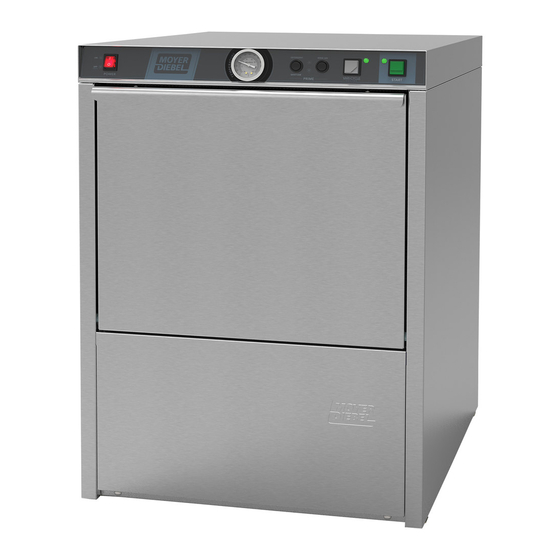
Installation/Operation Manual
201HT
201LT
3765 Champion Blvd.,
Winston-Salem, NC 27105
(336) 661-1556 Fax: (336) 661-1660
Toll-free: (800) 858-4477
with Service Replacement Parts
2674 N. Service Road, Jordan Station
Ontario, Canada L0R 1S0
(905) 562-4195 Fax: (905) 562-4618
Toll-free: (800) 263-5798
Undercounter Dishwashers
201HT
High Temperature Wash
Refresh with built-in booster
and Pumped Final Rinse
201LT
Low Temperature Chemical
Sanitization Wash Refresh
with Pumped Final Rinse
Issue Date: 7.17.15
Manual P/N
115743 rev. _
For machines beginning with S/N W150350341 and above
M4 Series
Printed in the USA
Advertisement
Chapters
Table of Contents


Need help?
Do you have a question about the 201HT M4 Series and is the answer not in the manual?
Questions and answers