Table of Contents
Advertisement
by
Installation/Operation Manual with Service Replacement Parts
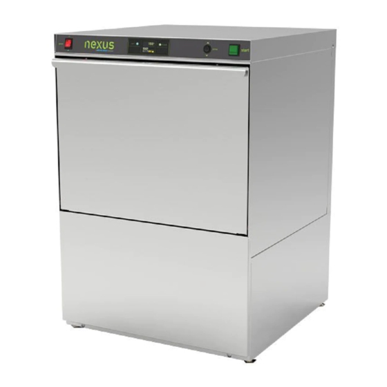
Model N900
2674 N. Service Road, Jordan Station
Ontario, Canada L0R 1S0
(905) 562-4195 Fax: (905) 562-4618
Toll-free: 1( 800) 263-5798
Undercounter Dishwashers
N900
High Temperature Wash and
Drain with built-in booster
and Pumped Final Rinse
Issue Date: 7.26.19
Manual P/N
0514004 Rev. -
For machines beginning with S/N W190688229 and above
Printed in the USA
Advertisement
Chapters
Table of Contents

Related Manuals for Moyer Diebel nexus N900


Summary of Contents for Moyer Diebel nexus N900
- Page 1 Installation/Operation Manual with Service Replacement Parts Undercounter Dishwashers N900 High Temperature Wash and Drain with built-in booster and Pumped Final Rinse Model N900 Issue Date: 7.26.19 Manual P/N 0514004 Rev. - For machines beginning with S/N W190688229 and above 2674 N. Service Road, Jordan Station Printed in the USA Ontario, Canada L0R 1S0 (905) 562-4195 Fax: (905) 562-4618...
- Page 2 National Service Department In Canada: In the USA: Toll-free: (800) 263-5798 Toll-free: (800) 858-4477 Tel: (905) 562-4195 Tel: (336) 661-1556 Fax: (905) 562-4618 Fax: (336) 661-1660 email: service@moyerdiebellimited.com email: service@moyerdiebel.com. ATTENTION The model no., serial no., voltage, Hz and phase are needed to identify your machine and to answer questions.
- Page 3 PRODUCT REGISTRATION ONLINE Connect to the internet and enter the URL below to register your machine. IN CANADA: https://www.moyerdiebel.com/warranty-registration...
- Page 4 PRODUCT REGISTRATION BY FAX COMPLETE THIS FORM AND FAX TO: 1 (800) 204-0109 in Canada PRODUCT REGISTRATION CARD Model Serial # Date of Installation: Company Name: Address: (Street) State Zip or Telephone #: ( or Province Postal Code Contact: Installation Company: Address: Telephone #: Contact:...
-
Page 5: Revision History
Revision History Revision History Specifications are subject to change based on continual product improvement. Revision Revised Serial Number Revision Date Pages Effectivity Description 7.26.19 W190688299 Released first edition... - Page 6 Machines found to have issues related to installation procedures, or DISCLAIMER OF WARRANTIES AND LIMITATIONS OF LIABILITY. MOYER DIEBEL’S delays of any kind, will not be covered by Moyer Diebel and the sole WARRANTY IS ONLY TO THE EXTENT REFLECTED ABOVE. MOYER DIEBEL responsibility of the equipment purchaser.
-
Page 7: Table Of Contents
Table of Contents Table of Contents Revision History ........................i Limited Warranty .........................ii ....................Installation Installation Codes ....................1 Receiving ......................1 Placement ......................1 Water Connection ....................2 Drain Connection ....................3 Electrical Connection ..................6 Booster Fill Procedure ..................10 Machine Start-up ..................... - Page 8 Blank Page This Page Intentionally Left Blank...
-
Page 9: Installation
Installation INSTALLATION CODES The installation of the dishwasher must comply with all local electrical, plumbing, health and safety codes or in the absence of local codes, installed in accordance with the applicable requirements in the National Electrical Code, NFPA 70, Canadian Electrical Code (CEC), Part 1, CSA C22.1;... -
Page 10: Water Connection
Installation WATER CONNECTION NOTE: The installation of the dishwasher must be performed by a qualified service personnel familiar with food service equipment. Problems due to improper installation are not covered by the Limited Warranty. The installation of the dishwasher must comply with all local electrical, plumbing, health and safety codes or in the absence of local codes, installed in accordance with the applicable requirements in the National Electrical Code, NFPA 70, Canadian Electrical Code (CEC), Part 1, CSA C22.1;... -
Page 11: Drain Connection
Installation DRAIN CONNECTION ! VERY IMPORTANT ! The dishwasher will not drain correctly if it is connected to a disposer. THE DRAIN HOSE IS LOOPED AND CLAMPED AND MUST NOT BE CHANGED. ALTERING THE DRAIN HOSE ROUTING MAY RESULT IN THE MACHINE’S INABILITY TO DRAIN OR MAY CAUSE THE MACHINE TO SIPHON THE WATER OUT OF... - Page 12 Installation DRAIN CONNECTION (continued) ! ATTENTION ! Failure to follow the drain connection instructions may void the warranty. Machine is equipped with a 6ft. [2m] 5/8" I.D. drain hose. The maximum drain height connection must not exceed 3ft. [1m] and must be vented to prevent wash tank siphoning. Drain hose is located at the rear of the machine and is secured by two clamps to maintain the anti-siphoning loop in the drain hose.
- Page 13 Installation Building Drain Connection Install the drain hose to an 1-1/2" or larger "WYE" fitting. Building drain system must be properly vented. Connection to a "TEE" fitting will prevent the dishwasher from draining completely Drain Hose 3/4" NPT Hose Barb Fitting Drain Adapter...
-
Page 14: Electrical Connection
Installation ELECTRICAL CONNECTION Connect Power to the Main Terminal Block NOTE: The installation of the dishwasher must comply with all local electrical, plumbing, health and safety codes or in the absence of local codes, installed in accordance with the applicable requirements in the National Electrical Code, NFPA 70, Canadian Electrical Code (CEC), Part 1, CSA C22.1;... - Page 15 Installation ELECTRICAL CONNECTION Connect Power to the Main Terminal Block WARNING: Electrocution may occur when working on energized circuits. Disconnect power at main breaker or service disconnect switch; lock out and tag to indicate work is being performed on the circuit. ! VERY IMPORTANT ! Provide a 3 feet/1 meter service loop in the power supply cable to service the machine.
- Page 16 Installation ELECTRICAL CONNECTION Connect Power to the Main Terminal Block Remove the lower front dishwasher panel (Fig. 5). Lower Front Dishwasher Panel Fig. 5 Remove the retaining fastener (A) from the main terminal block (Fig. 6) Fig. 6 Main Terminal Block Cover (continued on next page)
- Page 17 Installation ELECTRICAL CONNECTION Connect Power to the Main Terminal Block Refer to Fig. 7 below: Provide a 3 foot/1 meter service loop in the machine power supply cable. Route the power cable from machine rear to terminal block making sure the cable does not touch the booster tank.
-
Page 18: Booster Fill Procedure
Installation BOOSTER FILL PROCEDURE Fig.8 Follow the instructions to fill the booster tank prior to washing dishes. DO NOT TURN THE DISHWASHER POWER SWITCH ON Turn the main water supply to the machine ON. Turn the main breaker or disconnect power switch ON. Press and hold the dishwasher green start switch for three seconds to activate the fill solenoid. -
Page 19: Machine Start-Up
Installation MACHINE START-UP Chemical Dispensing Pumps ! VERY IMPORTANT ! ALWAYS USE A COMMERCIAL GRADE NON-CHLORINATED DETERGENT. PLACE THE CHEMICAL CONTAINERS AS CLOSE TO THE MACHINE AS POSSIBLE. DO NOT ELEVATE THE CONTAINERS ABOVE THE FINISHED FLOOR ! VERY IMPORTANT ! Contact a chemical supplier for detergent and rinse-aid chemicals. -
Page 20: Detergent And Rinse-Aid Injection Points
Installation Detergent and Rinse-aid Pump Injection Points ! VERY IMPORTANT ! ALWAYS USE A COMMERCIAL GRADE NON-CHLORINATED DETERGENT. PLACE THE CHEMICAL CONTAINERS AS CLOSE TO THE MACHINE AS POSSIBLE. DO NOT ELEVATE THE CONTAINERS ABOVE THE FINISHED FLOOR Injection Point Locations 1. - Page 21 Installation Priming the Chemical Dispensing Pumps ! VERY IMPORTANT ! The chemical dispensing pumps must be primed before operating the dishwasher and whenever the container is changed. PRIME Nexus Control Panel Fig.10 The chemical dispensing pump supply lines must be primed before the will pump properly.
-
Page 22: Operation
Operation NORMAL WASH MODE Control Panel In Cycle Wait Prime ON/OFF- DRAIN Start LED Light LED Light Push Button POWER SWITCH Push Button Close the door dishwasher front door. Push the Power Switch UP to turn on power. The power switch will illuminate and the machine will fill with water. Wait until the wash temperature indicates a minimum of 150°F/66°C. -
Page 23: Loading Dish Racks
Operation LOADING DISH RACKS ! VERY IMPORTANT ! DO NOT OVERLOAD THE DISH RACK. LOAD ONE DISH RACK INTO THE MACHINE AT A TIME. Prescrap and rinse the wares before loading to remove large food particles. Load soiled wares into the dish rack. Place plates and glasses in a peg rack. Place cups and bowls in an optional flat bottom rack. - Page 24 Operation Loading Dish Racks Load pots and pans in an peg rack or optional flat-bottom rack. Load utensils in a single layer in a peg rack or an optional flat-bottom rack. Load cups and bowls in a peg rack or an optional flat-bottom rack. NEVER stack dish racks.
-
Page 25: Operational Display
Operation OPERATIONAL DISPLAY The screen displays the operational status of the machine throughout the cycle. • Start-up Sequence 1. When power switch is turned ON, system information screen will show briefly. 2. This shows firmware version, parameter settings, and cycle counts. 1. -
Page 26: Sump Fill Level
Operation SUMP FILL LEVEL 1. After filling sequence is complete, water level should be 1/4” to 3/8” below level of sump flange. Operational Display (continued) WASH CYCLE WASH 1. The status indicator shows cycle progress. 2. In-cycle light is illuminated. DRAIN 1. -
Page 27: Rinse Sentry
Operation RINSE SENTRY AUTOCLEAN DRAIN 1. When machine is turned off, the AutoClean screen with the status indicator is shown. 2. This takes approximately 2-1/2 minutes. 3. When complete, open door to allow machine interior to air dry. -
Page 28: Cleaning
Cleaning Cleaning the Wash Tank ! VERY IMPORTANT ! DRAIN AND CLEAN THE DISHWASHER EVERY 2 HOURS OF CONTINUOUS OPERATION, AFTER EACH MEAL PERIOD AND AT THE END OF THE DAY. Remove the upper and lower spray arms and flush clean with water. Remove the scrap screen making sure food soils do not fall into tank. -
Page 29: Cleaning The Wash Arms
Cleaning Cleaning the wash arms: Unscrew the retaining screw from the upper and lower interchangeable spray arms. Flush the spray arms clean in a sink. Be sure to flush the wash arm bearings. USE GROVES TO LOSEN HUB FOR CLEANING. USE PAPER CLIP TO CLEAN NOZZLES... -
Page 30: Cleaning Scrap Screen And Sump Strainer
Cleaning Scrap Cleaning the Scrap Screen and Sump Strainer Lift the scrap screen straight up and out of the machine to prevent food particles from falling into the tank sump. Flush the scrap screen in a remote sink making sure to back-flush both side of the screen. Wipe the tank sump of water and debris. -
Page 31: Deliming
Deliming DELIMING WARNING: Death or serious injury may result when deliming solution is mixed with sodium hypochlorite (chlorine bleach) sanitizing agent. Mixing may cause hazardous gases to form. Deliming solution and other acids must never be mixed with chlorine, iodine, bromine, or fluorine. Deliming solutions can cause severe irritation and possible chemical burns. -
Page 32: Maintenance
Maintenance MAINTENANCE SCHEDULES Daily Maintenance Check all of the wash arm and rinse arm spray jets and clean as necessary. Check scrap screen, and sump strainer and clean as necessary. Make sure the water supply is on and the drain is not clogged. Check the temperature display and ensure it is operating. - Page 33 Blank This Page Intentionally Left Blank...
-
Page 34: Diagnostic Features
Diagnostics DIAGNOSTIC FEATURES To access diagnostic features: 1. Turn power switch to “OFF”. 2. Push start button 3 times. 3. Machine will now step through and operate the components as shown below. (continued on next page) - Page 35 Diagnostics...
-
Page 36: Sensor Fault
Diagnostics Diagnostic Features (continued) SENSOR FAULT 1. Sensor Fault Icon indicates machine requires servicing (wash, rinse, or booster sensor). 2. Machine will still operate at reduced capacity. 3. Caution Icon will continue to show during cycles. PARAMETER SETTINGS CAUTION: Parameter changes must be made by qualified personnel only. - Page 37 Diagnostics Parameter Settings (continued) To Change parameters: 1. Push and hold the “MENU” button. 2. DET setting screen will appear first. 3. Push menu button to scroll through until desired parameter is reached. 4. Push “CHANGE” button until desired setting is reached. 5.
- Page 38 Blank Page This Page Intentionally Left Blank...
-
Page 39: Service Parts
Service Replacement Parts Service Replacement Parts Illustrations Page Terminal Block ..........................32 Booster ............................34 Chemical Pumps .........................36 Control Panel ..........................38 Nozzles ............................40 Wash Arms ..........................42 Panels and Door .........................44 Rear Plumbing ..........................46 Sump ............................48 Dish Racks ..........................50... -
Page 40: Terminal Block
Terminal Block... - Page 41 Terminal Block Item Part Description Qty. 0313396 COVER, BOX WIRING 0501411 SCREW, 10-32 X 1/4", TRUSS HD. C120444 CONTACTOR, 3-POLE 220VAC COIL 0509527 BLOCK, TERMINAL, 4-POLE 103310 LUG, GROUND 0313395 BOX, WIRING 107964 BUSHING, STRAIN RELIEF, SMALL 0503592 LABEL, GROUND...
-
Page 42: Booster
Booster... - Page 43 Booster Item Part Description Qty. 0513988 HEATER, 5KW /220V 0513310 THERMISTOR, PROBE ASSY. 0512928 GASKET 0713850 BOOSTER, WELDED ASSY. 0512985 CLAMP, SS GEAR-MIN. 1/2" 0508817 PLUG 1/8 HEX COUNTERSUNK SS 0512185 BOLT, HEX FLANGE, 1/4-20 X 3/8" SST 108954 NUT, GRIP 6-32 W/NYLON INSERT SST 110562 THERMOSTAT, HIGH LIMIT 240°F 107417...
-
Page 44: Chemical Pumps
Chemical Pumps... - Page 45 Chemical Pumps Item Part Description Qty. 0505483 LABEL, RINSE-AID HOSE 0503695 LABEL, DETERGENT HOSE 0306363 TUBE, 3/8" ID X 12" LG. STIFFENER 0501869 STRAINER 0512985 CLAMP, SS GEAR-MIN. 1/2" 0512475-1 HOSE 4MM ID 6MM OD PVC 107417 HOSE, RUBBER 1/2" ID X .84" OD 0513986 RINSE AID PUMP 100007...
-
Page 46: Control Panel
Control Panel... - Page 47 Control Panel Item Part Description Qty. 0512221 SWITCH, ROCKER DPST 250V NEON 0513958 LABEL, FACIA NEXUS 0512320 GASKET, STEAM 0512357 STANDOFF, LED DISPLAY BOARD 0512978 SCREW 6-18 X 1/4 PAN HEAD PHILLIPS SS 0313957 PANEL, FACIA NEXUS, HT 0503580 NUT, 10-32 0501563 SCREW, #8 X 3/8"...
-
Page 48: Nozzles
Nozzles The number of dots on the nozzles correspond to the port in which it is assembled. The ports are keyed for the matching nozzle. Do not force a nozzle into the incorrect port. 1 DOT 2 DOTS 4 DOTS 5 DOTS 3 DOTS... - Page 49 Nozzles Item Part Description Qty. 0513992 NOZZLE 1, WASH ARM 0513993 NOZZLE 2, WASH ARM 0513990 WASH ARM 0513994 NOZZLE 3, WASH ARM 0513997 WASHER, BEARING WASH ARM 0513995 NOZZLE 4, WASH ARM 0513996 NOZZLE 5, WASH ARM 0514000 O-RING, NOZZLE WASH ARM 0513991 ENDCAP, WASH ARM 0513998...
-
Page 50: Wash Arms
Wash Arms... - Page 51 Wash Arms Item Part Description Qty. 0502571 CLAMP, HOSE GEAR HOSE 1-1/2” SST 107967 NUT, HEX SST 1/4-20 NYLON INSERT 0513968 HUB, UPPER WASH ARM 0501481 WASHER, NYLTITE 100736 BOLT 1/4-20 X 3/4" HEX HEAD 0512133 O-RING, 2-1/8" OD X 1-3/4" ID X 3/16" 0713971 ASSEMBLY, WASH ARM 0512120...
-
Page 52: Panels And Door
Panels and Door... - Page 53 Panels and Door Item Part Description Qty. 100007 SCREW, TRUSS SLOT SST 10-32 X 3/8" 0313955 PANEL, REAR 0713944 WELDMENT, BASE 0503718 FOOT, ADJUSTING 0514473 NUT 1/4-20 WH SERRATED SS 100779 SCREW, 1/4-20 X 5/8" TRUSS SS PHIL 0313956 PANEL, FRONT 0513647 CLIP CORD 5/8"...
-
Page 54: Rear Plumbing
Rear Plumbing... - Page 55 Rear Plumbing Item Part Description Qty. 0312145-2 BRACKET, DRAIN PUMP 0512185 BOLT, HEX FLANGE 1/4-20 X 3/8" SST 0514040 PUMP, DRAIN 0502571 CLAMP, HOSE GEAR 100003 NUT, PLAIN 1/4-20 SST 0513984 HOSE, PUMP DRAIN 107967 NUT, 1/4-20 W/NYLON INSERT SST 102383 WASHER 17/64 X 1/2 X 0.32 14S 107417...
-
Page 56: Sump
Sump... - Page 57 Sump Item Part Description Qty. 0513964 SCRAP SCREEN 0513981 PUMP SUCTION RING 0513962 GASKET, UPPER SUMP 0513970 HEATER, WASH TANK 0513961 SUMP BOWL 201029-1 LOCKNUT 1/2" NPT NP 0501836 O-RING 0512299 ADAPTOR, THERMISTOR 0513310 THERMISTOR, 10 KΩ, 2 WIRE ASSY 102383 WASHER 17/64"...
-
Page 58: Dish Racks
Dish Racks... - Page 59 Dish Racks Item Part Description Qty. 101273 OPTI0NAL DISH RACK, FLAT-BOTTOM 101285 DISH RACK, PEG...
-
Page 60: Electrical Schematic
Electrical Schematic SINGLE PHASE 4 AMP FUSE... -
Page 61: Timing Chart
Timing Charts... - Page 62 Blank Page This Page Intentionally Left Blank...
Need help?
Do you have a question about the nexus N900 and is the answer not in the manual?
Questions and answers
Dishwater is set to 165 degre F. Water temperature never reach more than 108 degre.
The Moyer Diebel N900 dishwasher may not be reaching the set temperature of 165°F due to the following possible causes:
1. Incoming hot water supply issue: The hot water must be at least 140°F at the machine and have a pressure between 25–95 psi. If the supply is below this temperature or pressure, the dishwasher may not reach the required rinse temperature.
2. Rinse Sentry mode delay: If the final rinse temperature does not reach 180–195°F, the Rinse Sentry mode will extend the cycle time. However, if the booster heater cannot reach the proper temperature within 5 minutes, the machine exits Rinse Sentry mode and completes the cycle without reaching the desired temperature.
3. Booster heater malfunction: If the booster heater is not functioning properly, it may not be able to raise the water temperature to the required level.
4. Scale buildup: Mineral deposits from hard water can reduce heating efficiency, preventing the machine from reaching the target temperature.
5. Improper deliming: If the dishwasher is not properly delimed, scale may inhibit proper heating.
These factors can prevent the dishwasher from reaching the set temperature of 165°F.
This answer is automatically generated
How to adjust detergent and rinse
To adjust detergent and rinse settings on the Moyer Diebel Nexus N900:
1. Use a Commercial Non-Chlorinated Detergent – Ensure you are using the correct detergent.
2. Place Chemical Containers Properly – Position them as close to the machine as possible and do not elevate them above the floor.
3. Locate Injection Points – Detergent and rinse-aid enter the wash tank through a fitting at the right-rear corner of the machine.
4. Prime Chemical Dispensing Pumps:
- Ensure containers are full and pick-up tubes are correctly placed.
- Turn on the dishwasher power switch to fill the machine with water.
- Open the dishwasher door.
- Push and hold the prime button in the detergent position until the pump is primed.
For precise adjustments, refer to the adjustment screw labeled in the manual.
This answer is automatically generated
How much detergent and rinse aid are used during operation of N900 per cycle?