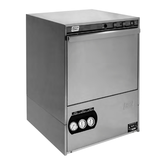
Moyer Diebel 351HT Installation & Operation Manual
Undercounter high temperature dishwasher
Hide thumbs
Also See for 351HT:
Table of Contents
Advertisement
Installation/Operation Manual with Service Replacement Parts
3765 Champion Blvd.
Winston-Salem, NC 27105
336/661-1992 Fax: 336/661-1660
Toll-free: 800/ 858-4477
351HT
2674 N. Service Road, Jordan Station
Ontario, Canada L0R 1S0
905/562-4195 Fax: 905/562-4618
Toll-free: 800/ 263-5798
Undercounter
High Temperature
Dishwasher
Models:
351HT
Issue Date: 6.9.11
Manual P/N
0512864 rev. D
For machines beginning with S/N W090217876 and above
Machine Serial No.
Printed in the USA
Advertisement
Chapters
Table of Contents

Related Manuals for Moyer Diebel 351HT


Summary of Contents for Moyer Diebel 351HT
- Page 1 Installation/Operation Manual with Service Replacement Parts Undercounter High Temperature Dishwasher Models: 351HT 351HT Machine Serial No. Issue Date: 6.9.11 Manual P/N 0512864 rev. D For machines beginning with S/N W090217876 and above 3765 Champion Blvd. 2674 N. Service Road, Jordan Station...
- Page 2 The USGBC and the CaGBC Member Logos are trademarks owned by the U.S. Green Building Council and The Canadian Green Building Council, respectively, and are used by permission. The logos signify only that Moyer Diebel is a USGBC member and a CaGBC member; USGBC and CaGBC do not review, certify nor endorse the products or services offered by its members.
- Page 3 REGISTER YOUR PRODUCT ONLINE Make sure you are connected to the internet then click or enter the address below. In the U.S.A http://www.moyerdiebel.com/register In Canada http://www.championindustries.com/canada/register...
-
Page 4: Product Registration
PRODUCT REGISTRATION BY FAX COMPLETE THIS FORM AND FAX TO: (336) 661-1660 in the USA (905) 562-4618 in Canada PRODUCT REGISTRATION CARD Model Serial # Date of Installation: Company Name: Address: (Street) Province Postal Code Telephone #: ( Contact: Installation Company: Address: Telephone #: Contact:... -
Page 5: Revision History
Revision History Revision History A revision might be a part number change, a new instruction, or other information that was not available at print time. We reserve the right to make changes to these instructions without notice and without incurring any liability by making the changes. Equipment owners may request a revised manual, at no charge, by calling 1 (800) 858-4477 in the USA or by calling 1 (800) 263-5798 in Canada. -
Page 6: Limited Warranty
If a defect in workmanship or material is found to exist within the warranty period, Moyer Diebel, at its election, will either repair or replace the defective machine or accept return of the machine for full credit; provided;... -
Page 7: Table Of Contents
Table of Contents Table of Contents Model 351 Undercounter Dishwasher Revision History ......................i Limited Warranty ......................ii Model Descriptions ......................iv ....................Installation Receiving ..............1 Electrical Connections ..........2 Water Connections .............4 Drain Connections ............5 ..................Initial Start-up Booster Fill Switch ............6 Assembly ............8 Chemical Dispensing Pumps ........9 Priming ......10... -
Page 8: Model Descriptions
Model Description Model Description 351HT High temperature hot water sanitizing dishwasher with built-in 40°F/22°C rise booster heater. 208-240VAC/60/1 Optional Equipment (consult factory) 70°F/39°C rise built-in booster heater 1-RDT Dish table 17" stand 17" Storage cabinet 6" legs (set of 4) -
Page 9: Installation
Installation Receiving NOTE: The installation of your dishwasher must be performed by qualified service personnel. Problems due to improper installation are not covered by the Warranty. Inspect the outside of the dishwasher carton for signs of damage. Remove the carton and inspect the dishwasher for damage. Check for any accessories that may have shipped with your dishwasher. -
Page 10: Electrical Connections
Installation Electrical Connections WARNING: Electrocution or serious injury may result when working on an energized circuit. Disconnect power at the main breaker or service disconnect switch before working on the circuit. Lock-out and tag the breaker to indicate that work is being performed on the circuit. - Page 11 Installation Electrical Connections 1. Refer to the connection diagram on the preceding page and the photo below: 2. Machines require a 3-wire plus ground supply which includes a current carrying neutral. 3. Power connections are made at the Main Terminal Block (MTB). 4.
-
Page 12: Water Connections
Installation Water Connections Note Plumbing connections must comply with national, local plumbing and sanitary codes. IMPORTANT Make sure the flexible water supply and drain hoses are not kinked. All models have a 6 ft. flexible hot water fill hose with a 3/4" NPS connector. A 1/2"... -
Page 13: Drain Connections
Installation Drain Connections ATTENTION Do not connect the drain hose to a disposer. The dishwasher will not drain correctly. The dishwasher has a 6ft. 3/4" I.D. drain hose. The maximum drain height connection must not exceed 3 ft.[0.9 m]. The drain hose is secured to the rear of the machine by a clamp to maintain a goose-neck bend in the drain hose. -
Page 14: Initial Start-Up
Initial Start-Up Filling the Booster ATTENTION VERIFY THE CORRECT VOLTAGE IS SUPPLIED TO THE MACHINE THE CORRECT SUPPLY VOLTAGE IS 115/208-240VAC/60/1. (Refer to the diagram on page 3.) Note: The dishwasher contains a built-in booster heater that was drained prior to shipment and must be filled with water before operating the dishwasher. - Page 15 Initial Start-Up Filling the Booster (continued) B) Press and hold the Booster Fill Switch down to the BOOSTER FILL position until you hear the water spraying inside the dishwasher wash tank, then release the switch. C) Push the switch up to the ON position and release. The booster tank is filled.
-
Page 16: Assembly
Initial Start-up Check List Remove any protective film from dishwasher. Check the interior for foreign material. Make sure the dishwasher is permanently located. Make sure all utility connections are complete. Make sure the flexible drain hose and the hot water fill hose are not kinked. Make sure the chemical supply containers are full and the chemical pick-up tubes are installed in the proper containers. -
Page 17: Chemical Dispensing Pumps
Initial Start-up Chemical Dispensing Pumps ATTENTION Contact a local chemical supplier for detergent and rinse-aid chemicals. The detergent should be a non-chlorinated liquid detergent. The chemical dispensing pumps are adjusted by the chemical supplier. The dishwasher is equipped with a built-in detergent dispensing pump and rinse-aid dispensing pump. - Page 18 Initial Start-up Chemical Dispensing Pumps (continued) Chemical Injection Points The illustrations below show the location of the detergent and the rinse-aid injection points. Detergent Injection Point Rinse-aid Injection Point Detergent enters the wash tank compartment through a fitting on the rear wall of the wash tank compartment. The rinse-aid enters the final rinse piping at the top-rear of the dishwasher near the vacuum breaker.
-
Page 19: Priming
Initial Start-up Chemical Dispensing Pumps Priming the Chemical Dispensing Pumps The chemical dispensing pumps must be primed before the dishwasher is operated. A 2-position PRIME switch is located on the front control panel to do this. The Detergent dispensing pump is primed when the Prime switch is pushed UP to the DET position. -
Page 20: Chemical Dispensing Pumps
Initial Start-up Chemical Dispensing Pumps Adjusting the Chemical Dispenser Pumps The amount of detergent and rinse-aid dispensed during the dishwasher cycle is controlled by adjustable cams on the timer assembly. Variables such as the type of chemicals used and the hardness of the water supply often require that the timer cam settings must be changed. -
Page 21: Operation
Operation Normal Wash Mode Follow the instructions below to operate the dishwasher in a Normal Wash Mode. A Rinse Sentry feature holds the dishwasher in a wash mode if the booster heater temperature is below 180ºF/82ºC. Turn the main power on at the main circuit breaker. Install the sump filter, overflow tube and spray arms. -
Page 22: Rinse Sentry Mode
Operation Normal Wash Mode (continued) 11. Opening the door when the dishwasher is in-cycle will stop the dishwasher. The cycle will resume automatically when the dishwasher door is closed fully. 12. The final rinse cycle begins at the end of the wash cycle and runs for approximately 15 seconds Check the RINSE temperature gauge during the final rinse and make sure it indicates a minimum of 180ºF/82ºC. -
Page 23: Cleaning And Maintenance
Cleaning and Maintenance Cleaning After Each Meal Period or every 8 Hours of Operation. Press the lighted power switch to the OFF position. The power switch light will go out. Open the door and remove the overflow tube from the wash tank sump. Inspect and clean the overflow tube rubber seal Close the door. - Page 24 Cleaning and Maintenance Cleaning At the End of the Day Perform Steps 1-9 on the previous page. Remove the upper and lower rinse and wash spray arms. The spray arms are interchangeable. Unscrew the rinse arm pin (A). Remove the rinse arm assemblies Clean the final rinse arm nozzles using a small paper clip (B).
-
Page 25: De-Liming
Cleaning and Maintenance De-liming Minerals accumulate on the interior surfaces of the dishwasher. The deposits have a white haze and, in cases of heavy accumulation, may appear as a granular solid. The generic name for mineral deposits is lime. The removal of lime deposits is called de-liming. Your dishwasher should be de- limed regularly;... -
Page 26: Maintenance
Cleaning and Maintenance Maintenance Follow the maintenance schedules below to keep the dishwasher operating most efficiently. Daily Maintenance Check all of the wash arm and rinse arm spray jets and clean as necessary. Make sure the water supply is on and the drain is not clogged. Check the temperature gauges and/or displays to ensure they are operating. -
Page 27: Troubleshooting
Troubleshooting Troubleshooting Condition Cause Solution Dishwasher will not run. Door not closed. Close door completely. Main power OFF. Check breaker on panel. Dishwasher OFF. Turn dishwasher ON. Low or no water. Main water supply off. Open supply valve. PRV setting incorrect Adjust the PRV setting Solenoid strainer clogged. - Page 28 Blank Page This Page Intentionally Left Blank...
-
Page 29: Service Replacement Parts
Service Replacement Parts Service Replacement Parts Illustrations Page Wash Pump/Motor Assembly ..........................Booster Assembly ..............................Electrical Panel and Timer Assembly ........................Control Panel Assembly ............................Upper Final Rinse Piping Assembly ........................Wash and Rinse Spray Arm Assemblies ........................ Drain Pump and Lower Hose Assemblies ......................Wash Tank Heater and Drain Assemblies ...................... -
Page 30: Wash Pump/Motor Assembly
Wash Pump/Motor Assembly... - Page 31 Wash Pump/Motor Assembly Item Part Description Qty. 0512340 SCREW, M4, PHIL, PAN HD. 0512341 IMPELLER HOUSING COVER 114144 NUT, M6 (left-hand thread) 0501501 WASHER, LOCK, 1/4" 0501478 WASHER, PLAIN, 17/64" 0512345 IMPELLER 114139 SEAL, PUMP 110285 GASKET, PUMP 114137 PLATE, PUMP BACKING 107337 NUT, M4 0512101-1...
-
Page 32: Booster Assembly
Booster Assembly... - Page 33 Booster Assembly Item Part Description Qty. 0512847 HEATER, BOOSTER 4kW, 208V, 40°F RISE (Does not include gasket) 0512848 HEATER, BOOSTER 6kW, 220V, 70°F RISE (Does not include gasket) 0512928 GASKET, BOOSTER HEATER 0512108 THERMOSTAT, CONTROL 195°F 0512185 BOLT, HEX FLANGE, 1/4-20 X 3/8" SST 0502572 CLAMP, GEAR-TYPE 5/16"...
-
Page 34: Electrical Panel And Timer Assembly
Electrical Panel and Timer Assembly Item 8, Timer Assembly includes: Items 9 and 10... - Page 35 Electrical Panel and Timer Assembly Item Part Description Qty. 0507323 THERMOSTAT, WASH TANK 0512108 THERMOSTAT, BOOSTER 195°F 0501373 SWITCH, 3-POSITION, TOGGLE 0512935 LABEL, ON/OFF/BOOSTER FILL 0512934 LABEL, WASH-RINSE TEMPERATURE 0501450 SCREW, NIBS RH 6-32 X 3/16" PHIL. SST 0512875 BUSHING, 1" ID 0512862 ASSEMBLY, TIMER (Includes Items 9, 10) 0512916...
-
Page 36: Control Panel Assembly
Control Panel Assembly... - Page 37 Control Panel Assembly Item Part Description Qty. 0312902 PANEL, FACIA, 351 0512859 LABEL, FACIA, 351 0512922 SWITCH, ON-OFF 0512216 CONTACT, MOMENTARY, N.O. 0512217 HOUSING, SWITCH 0512218 BUTTON, SWITCH (GREEN) 0512219 BUTTON, SWITCH (GREY) 0512921 LIGHT, INDICATOR LED, 125VAC (GREEN) 0512226 SWITCH, MOMENTARY (PRIME) 0512320 GASKET, STEAM...
-
Page 38: Upper Final Rinse Piping Assembly
Upper Final Rinse Piping Assembly... - Page 39 Upper Final Rinse Piping Assembly Item Part Description Qty. 107417 HOSE, RUBBER 1/2ID X .84OD 0503679 CLAMP, SS GEAR-MIN. 5/16-MAX.7/8 112728 FITT COMP 1/4OD X 1/8MPT ELL J 0508817 PLUG, 1/8 HEX COUNTERSUNK 0513110 MANIFOLD, RINSE 112763 INJECTOR FITTING 112883-1 TUBING, 1/8OD X 1/16 ID 100003 NUT, HEX SS 1/4-20...
-
Page 40: Wash And Rinse Spray Arm Assemblies
Wash and Rinse Spray Arm Assemblies... - Page 41 Wash and Rinse Spray Arm Assemblies Item Part Description Qty. 0501478 WASHER, 17/64 id X 9/16" OD SST 107967 NUT, HEX 1/40-20 NYLON INSERT SST H35509 HUB, UPPER WASH ARM 107873 WASHER, PACKING 110215 SCREW, RETAINING 0502571 CLAMP, HOSE GEAR 1-1/2" SST 0512120 HOSE, UPPER WASH ARM 0712749...
-
Page 42: Drain Pump And Lower Hose Assemblies
Drain Pump and Lower Hose Assembly From Final Rinse Manifold To upper washarm hub... - Page 43 Drain Pump and Lower Hose Assembly Item Part Description Qty. 0512925 HOSE, FILL 1/2" X 7' C/W 3/4" FNPS 0512185 BOLT, HEX FLANGE, 1/4-20 X 3/8" SST 0512926 HOSE, BOOSTER FILL, 1/2" X 1' 0502572 CLAMP, HOSE GEAR-TYPE 5/16" 0502563 CLAMP, HOSE GEAR-TYPE, 1", SST 0502668 HOSE, DRAIN PUMP SUCTION...
-
Page 44: Wash Tank Heater And Drain Assemblies
Wash Tank Heater and Drain Assembly... - Page 45 Wash Tank Heater and Drain Assembly Item Part Description Qty. 0512930 GASKET, DOOR 0512846 HEATER, WASH TANK, 2KW, 240VAC 100003 WASHER, SPLIT LOCK 1/4" SST 0501539 NUT, HEX 1/4-20 SST 0501836 O-RING 0508873 ADAPTER, THERMOSTAT 0512920 BUSHING, THERMOSTAT (Use with Item 8) 0507323 THERMOSTAT, WASH TANK 0508872...
-
Page 46: Fill Solenoid Valve Assembly
Fill Solenoid Valve Assembly... - Page 47 Fill Solenoid Valve Assembly Item Part Description Qty. 0512853 VALVE, WATER INLET 115VAC/60/1 (Includes Items 2 and 3) 0512861 COIL, 115VAC/60/1 7W 0512860 KIT, REPAIR SOLENOID VALVE 0512185 BOLT, HEX FLANGE 1/4-20 X 3/8" SST 0312893 BRACKET, VALVE...
-
Page 48: Detergent Pump Assembly
Detergent Pump Assembly Yellow Rollers Check the squeeze tube every 6 months for wear. To Injection Point... - Page 49 Detergent Pump Assembly Item Part Description Qty. 0501869 STRAINER 0306363 TUBE,1/2IDX11-7/8LG. STIFFENER 0503695 LABEL, DETERGENT 0502667 HOSE, 1/4ID X 3/8OD PVC 0501519 TIE, NYLON 4" 0502644 ELBOW, 1/4 HOSE BARB 0512369 CLAMP, SNAP HOSE 114202 TUBE ASY,SANTOPRENE, 3/16 X 3/8 X 8.5 LG 114203 PUMP HD KIT, PERISTALIC (Yellow Rollers)
-
Page 50: Rinse-Aid Pump Assembly
RInse-Aid Pump Assembly Pink Rollers Check the squeeze tube every 6 months for wear. To Injection Point... - Page 51 Rinse-Aid Pump Assembly Item Part Description Qty. 0510872-1 GEARMOTOR, RINSE-AID 115/60/1 0512325 PUMP HEAD, PERISTALTIC (PINK ROLLERS) 112759 TUBE, PUMP 1/8" id X 9" LG. 0512369 CLAMP, HOSE 0501519 TIE, CABLE 4" 112883 TUBING, 1/8" OD X 1/16" ID 0505483 LABEL, RINSE AID 0306363 TUBE, 1/2"...
-
Page 52: Panel Assembly
Panel Assembly... - Page 53 HOLDER, GUAGE 109812 GAUGE, PRESSURE 0-60PSI 0512107 THERMOMETER, 2" DIAL, 7' CAPILLARY 100779 SCREW, 1/4-20 X 5/8" TRUSS HD. PHIL. SST 0312899 PANEL, FRONT 351HT 0503580 NUT, KEPS, 10-32 SST 0503718 FOOT, ADJUSTING 0512761 CLAMP, DOUBLE CONDUIT 0312905 WRAP, OUTER PANEL...
-
Page 54: Door Assembly
Door Assembly... - Page 55 Door Assembly Item Part Description Qty. 0713141 DOOR WELDED ASSY 0312892 ARM, DOOR SPRING 0512854 SPRING, DOOR 0312908 ACTUATOR, DOOR SWITCH 0503745 SCREW, 8-32 X 3/16" PHIL. SST...
- Page 56 Dish Racks, Line Strainer, PRV...
- Page 57 Dish Racks, Line Strainer, PRV Item Part Description Qty. 101273 DISH RACK, FLAT-BOTTOM 101285 DISH RACK, PEG 104421 STRAINER, LINE 1/2" BRONZE (OPTIONAL) 108265 VALVE, PRESSURE REGULATING, 1/2"...
-
Page 58: Dish Racks, Line Strainer And Pressure Regulating Vavle (Prv)
Electrical Schematic,Timer Chart, Fill/Drain Timer Electrical Schematic,Timer Chart Illustrations Page Model 351HT Electrical Schematic ......................Timer Chart ............................. Fill/Drain Timer Illustrations Page Theory of Operation.......................... -
Page 59: Electrical Schematic
Model 351HT - Electrical Schematic TO CUSTOMERS DISCONNECT SWITCH PER LOCAL ELECTRICAL CODE 115-208/230V/1PH 60HZ WHTR DRAIN SWITCH DOOR SWITCH START SWITCH 1HTR BOOSTER HEAT 208/230 VAC 4 kW SR1-2 DIAGRAM STATE RINSE HOMING END OF CYCLE SENTRY POWER-OFF DOOR-OPENED... -
Page 60: Timer Chart
Timer Chart - Model 351HT... -
Page 61: Fill/Drain Timer -Theory Of Operation
Theory of Operation - Fill/Drain Timer Fill/Drain Timer - Theory of Operation The Fill/Frain Timer provides both automatic fill and semi-automatic drain functions for the dishwasher. It is located on the back of the electrical component panel and it operates as follows: Fill 1. - Page 62 Blank Page This Page Intentionally left Blank...
Need help?
Do you have a question about the 351HT and is the answer not in the manual?
Questions and answers