
Subscribe to Our Youtube Channel
Related Manuals for OutBack Power FXR International Series


Summary of Contents for OutBack Power FXR International Series
- Page 1 FXR International Series Inverter/Charger FXR2012E FXR2024E FXR2348E VFXR2612E VFXR3024E VFXR3048E Operator’s Manual...
- Page 2 About OutBack Power OutBack Power™ is a leader in advanced energy storage and conversion technology. OutBack Power products include true sine wave inverter/chargers, batteries, maximum power point tracking charge controllers, and system communication components, as well as circuit breakers, accessories, and assembled systems.
-
Page 3: Table Of Contents
Introduction ..................7 Audience ........................... 7 Symbols Used ........................... 7 General Safety .......................... 7 Welcome to OutBack Power ..................... 8 Inverter Functions ........................9 Product Compatibility ......................... 10 Inverter Controls ........................10 MATE3-Class System Display and Controller ..................11 ... - Page 4 Table of Contents Troubleshooting ................. 49 Basic Troubleshooting ......................49 Error Messages ........................54 Warning Messages ......................... 55 Temperature Events ........................... 56 GT Warnings ............................56 Disconnect Messages ......................57 Sell Status ..........................58 Specifications ..................59 ...
- Page 5 Table of Contents List of Tables Table 1 FXR/HUB Compatibility with Other OutBack Products ..........10 Table 2 System Display Compatibility .................. 11 Table 3 Battery Indicator Values ..................13 Table 4 Summary of Input Modes ..................24 Table 5 Charge Currents for FXR Models ................
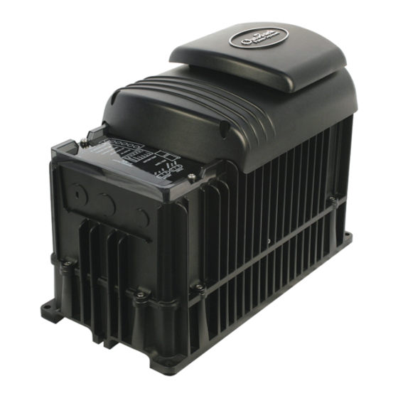
- Page 6 Table of Contents List of Figures Figure 1 FXR Series Inverter/Charger with Turbo Fan ............8 Figure 2 LED Indicators ......................13 Figure 3 Inverter Status LED Indicators ................14 Figure 4 Charging Stages Over Time ..................34 Figure 5 Charging Stages Over Time (24/7) .................
-
Page 7: Introduction
AC and DC voltage up to 600 volts. This product is only serviceable by qualified personnel. Do not use this product without reading the FXR International Series Inverter/Charger Installation Manual. -
Page 8: Welcome To Outback Power
Thank you for purchasing the FXR Series Inverter/Charger. It is designed to offer a complete power conversion system between batteries and AC power. As part of an OutBack Power Grid/Hybrid™ system, it can provide off-grid power, grid backup power, or grid-interactive service which sells excess renewable energy back to the utility. -
Page 9: Inverter Functions
This product has a settable AC output range. In this book, many references to the output refer to the entire range. However, some references are made to 20 Vac or 60 Hz output. These are intended as examples only. Outback Power Technologies Intuitive Control System for Renewable Energy 900-0169-01-00 Rev C... -
Page 10: Product Compatibility
Introduction Product Compatibility The OutBack Power networking products (such as the HUB 10.3) can work with the Radian inverter and other OutBack Power products. This applicability is not universal. Table 1 describes which products can be networked. Table 1 FXR/HUB Compatibility with Other OutBack Products... -
Page 11: Mate3-Class System Display And Controller
Introduction MATE3-Class System Display and Controller IMPORTANT: Some functions are not based in the inverter, but are part of the system display’s firmware. They will not function if the system display is removed. The MATE3 class of system display products (sold separately) includes the MATE3, the MATE3 , and the MATE3 . - Page 12 Introduction THIS PAGE INTENTIONALLY LEFT BLANK. 900-0169-01-00 Rev C ©2015 EnerSys. All Rights Reserved.
-
Page 13: Operation
If they have any loads, a charging source, or are at another temperature, their voltage may not reflect their true state. The OutBack FLEXnet DC is an OutBack Power battery monitor that can be added to the system to provide accurate measurements. -
Page 14: Status Indicators
Operation Status Indicators (Green): TATUS NVERTER Solid: The FXR inverter is on and providing power. If accompanied by a solid yellow AC I indicator (2), the inverter is also connected to the utility grid with an AC input mode that uses both inverter power and grid power (Support, Grid Tied, or GridZero). -
Page 15: Inverter Functionality
Operation Inverter Functionality The FXR inverter can be used for many applications. Some of the inverter’s operations occur automatically. Others are conditional or must be enabled manually before they will operate. Most of the inverter’s individual operations and functions can be programmed using the system display. -
Page 16: Description Of Ac Input Modes
Operation Description of AC Input Modes These modes control aspects of how the inverter interacts with AC input sources. Each mode is intended to optimize the inverter for a particular application. The names of the modes are Generator, Support, Grid Tied, UPS, Backup, Mini Grid, and GridZero. The modes are summarized and compared in Table 4. -
Page 17: Support
Operation Support The Support mode is intended for systems that use the utility grid or a generator. In some cases the amount of current available from the source is limited due to size, wiring, or other reasons. If large loads need to be run, the FXR inverter augments (supports) the AC source. The inverter uses battery power and additional sources to ensure that the loads receive the power they demand. -
Page 18: Grid Tied
Operation Grid Tied IMPORTANT: Selling power to the utility company requires the authorization of the local electric jurisdiction. How the utility company accommodates this will depend on their policies on the issue. Some may pay for power sold; others may issue credit. Some policies may prohibit the use of this mode altogether. -
Page 19: Grid Interface Protection Menu
Operation Grid Interface Protection Menu Grid-interactive requirements vary in different locations around the world. The grid-interactive settings are adjustable in the Grid Interface Protection menu. This is only available with installer-level access. These settings are generally controlled by the local authorities or interconnection agreement and should not be altered by the end user. -
Page 20: Ups
Operation If selected to Yes, the AC source is required to deliver appropriate input to all inverters in a stacked system. If the master or subphase master inverters do not sense an acceptable AC source, the entire system disconnects from the source. None of the inverters will reconnect until the source is acceptable for the duration of the appropriate timer. -
Page 21: Mini Grid
Operation Mini Grid In Mini Grid mode, the FXR inverter automatically rejects an AC source and runs solely from battery (and renewable) energy. The inverter only connects to the AC source (usually the utility grid) when the batteries run too low. The FXR inverter runs on battery-supplied power for as long as the batteries can be sustained. - Page 22 Operation When deciding whether to use Mini Grid or HBX, the user should consider the aspects of each. • Mini Grid logic is based in the FXR inverter. After programming, it can function in the absence of the system display. HBX logic is based in the system display. It cannot function unless the system display is installed and operating.
-
Page 23: Gridzero
Operation GridZero In GridZero mode, the inverter remains grid-connected, but prioritizes the use of battery or renewable sources to run loads. It uses only renewable energy to recharge the batteries. The inverter tries to “zero” the grid use, drawing on AC power only when needed to supplement stored DC sources. -
Page 24: Table 4 Summary Of Input Modes
Operation Table 4 Summary of Input Modes Mode Summary Benefits Cautions Intended Charger Generator Accepts power Can use AC that may be Will pass irregular or Source: Performs three- from an unusable in other modes low-quality power to the Generator stage charge and irregular or... - Page 25 Operation NOTES: 900-0169-01-00 Rev C...
-
Page 26: Description Of Inverter Operations
Operation Description of Inverter Operations The items in this section are operations common to all FXR inverters. These are used in most or all of the input modes described in the preceding section. Some of the items in this section are functions which can be manually selected, enabled, or customized. -
Page 27: Ac Frequency
Operation Low Battery Cut-In: The recovery point from Low Battery Cut-Out. When the DC voltage rises above this point for 1 minute, the error will clear and the inverter will resume functioning. Connecting an AC source for the inverter to charge the batteries will also clear a low battery error. Output Voltage: The AC output voltage can be adjusted. -
Page 28: Search
Operation Search An automated search circuit is available to minimize the power draw when no loads are present. When enabled, the inverter does not always deliver full output. The output is reduced to brief pulses with a delay between them. These pulses are sent down the output lines to see if a resistance is present. -
Page 29: Input
Operation Input When the input terminals are connected to a stable AC source, the inverter will synchronize itself with that source and use it as the primary source of AC power. Its transfer relay will engage, linking the AC source directly with the inverter’s output. It can also use the source to charge batteries. -
Page 30: Ac Source Acceptance
Operation AC Source Acceptance The input source must meet the following specifications to be accepted. This is true in all modes except Grid Tied: Voltage (both input selections): 208 to 252 Vac Frequency (both input selections): If the output frequency is set to 50 Hz (default), the input acceptance range is 45 to 55 Hz. - Page 31 Operation Multiple Inverters In a stacked system, whenever the master inverter senses acceptable input, it orders all other inverters to transfer to the AC source. The other inverters do not use their own input readings to transfer. It is expected that the AC source delivers input (in the appropriate phase) to all inverters.
-
Page 32: Generator Input
Operation Generator Input A generator should be sized to provide enough power for all inverters, both for loads and for battery charging. The generator’s voltage and frequency must match the FXR inverter’s acceptance settings. Some generators may not be able to maintain AC voltage or frequency for long periods of time if they are loaded more than 80% of rated capacity. -
Page 33: Battery Charging
75 Adc. (75 ÷ 2.5 = 15 Aac) Bank consists of 12 × OutBack Power EnergyCell 200RE VRLA batteries in series/parallel for a 24-volt system. Recommended maximum charge current is 90 Adc. (90 ÷ 10 = 9 Aac) The maximum DC charge rate for FXR models is specified in Table 15 on page 59. -
Page 34: Charge Cycle
Operation Limiting Charge Current (Multiple Inverters) It is not advisable to set Charger AC Limit less than 6 Aac in a stacked system. The Power Save function requires the master to activates the slave chargers in sequence only when the charge current exceeds 5 Aac. -
Page 35: Advanced Battery Technologies
Operation Advanced Battery Technologies Advanced battery technologies such as lithium-ion and sodium-sulfur may require very different settings from the inverter’s defaults or the three-stage cycle in general. The Charging Steps section describes the individual selections and behavior. All charger settings are adjustable for different priorities. - Page 36 Operation Time limit: Absorb Time setting. The charger does not necessarily run through its full duration if it retained time from a previous charge cycle. The timer counts down from the inception of Absorption stage until it reaches zero. The time remaining can be viewed in the system display. The Absorption timer does not reset to its maximum amount, or to zero, when AC power is disconnected or reconnected.
-
Page 37: New Charging Cycle
Operation Time limit: Float Time setting. The charger will go Silent once the timer has expired (if another stage is not still in progress.) The Float timer is reset to its maximum amount whenever the batteries decrease to the Re-Float Voltage setting. NOTE : The Float timer begins running any time the battery voltage exceeds the Float Voltage set point. -
Page 38: Figure 6 Repeated Charging (1 St And 2 Nd Cycles)
Operation Voltage Cycle 1 Cycle 2 AC Loss Refloat Absorption Silent Refloat Float Float Silent Absorption Set Point Float Set Point Re-Float Set Point Absorption Float timer Float timer runs Float timer runs timer runs resets Time (part) Inverter now charging to a new set Inverter completed charging;... -
Page 39: Figure 7 Repeated Charging (3 Rd , 4 Th , And 5 Th Cycles)
Operation Cycle 3 Cycle 4 Cycle 5 AC Loss AC Loss AC Loss Absorption Silent Bulk Absorption Silent Bulk Bulk Absorption Set Point Float Set Point Re-Bulk Set Point Absorption Absorption Absorption Absorption Absorption timer resets timer runs timer runs timer timer runs (complete) (part) -
Page 40: Equalization
Operation Equalization Equalization is a controlled overcharge that is part of regular battery maintenance. Equalization brings the batteries to a much higher voltage than usual and maintains this high voltage for a period of time. This has the result of removing inert lead sulfate compounds from the battery plates. - Page 41 The communications manager and system display must still be present to share the values. IMPORTANT: If the RTS is connected to an OutBack Power device other than those listed above, the compensation values will not be shared. If a system display is not connected, the compensation values will not be shared.
-
Page 42: Offset
Operation Offset Offset is an automatic operation which occurs in certain conditions. It is not a programmable inverter function. This operation uses excess battery energy to power the loads when an AC source is present. The system can take advantage of renewable energy sources, “offsetting” dependence on the AC source. -
Page 43: Auxiliary Terminals
Operation Auxiliary Terminals The FXR inverter has an auxiliary (“A “) output that responds to different criteria to control certain operations. These terminals provide a 12 Vdc output that can deliver up to 0.7 Adc. The A output has three states: continuous Off, continuous On, and Auto, which allows that output to be activated using the automatic auxiliary functions. - Page 44 Operation Settable Gen Alert parameters include: Low and high DC voltage On and off delay Gen Alert control logic is located in the inverter. It has the advantage of functioning when the system display is removed. However, it may not completely charge the batteries and does not have all the advantages of the Advanced Generator Start (AGS) function that is found in the system display.
-
Page 45: Table 7 Aux Mode Functions
Operation When battery voltage rises above a settable high voltage level, the A is activated after a settable delay. The output controls a larger relay, which allows current to flow from the batteries to a dedicated AC load when energized. Diversion is usually used to regulate battery charging. The AC device is usually wired to the output or load panel and must be left on. - Page 46 Operation NOTES: 900-0169-01-00 Rev C ©2015 EnerSys. All Rights Reserved.
-
Page 47: Metering
Metering MATE3 System Display Screens The MATE3 system display can monitor the inverter and other networked devices. From the Home screen, the < Inverter > “soft” key accesses the inverter monitoring screens. Inverter Soft Key Figure 8 Home Screen Inverter Screen The <... -
Page 48: Battery Screen
Metering Charge displays the kilowatts and AC amperage consumed for the inverter to charge the battery bank. This line also shows the present charging stage. Load displays kilowatts and AC amperage consumed by devices on the inverter’s output. It can be the same as Invert. -
Page 49: Troubleshooting
Troubleshooting Basic Troubleshooting Table 8 is organized in order of common symptoms, with a series of possible causes. Each also shows possible troubleshooting steps, including system display checks where appropriate. In troubleshooting, AC voltages can be measured at the attachment screw for each AC conductor. - Page 50 Troubleshooting Table 8 Troubleshooting Symptom Possible Cause Possible Remedy One or more units Check Power Save Levels in the Inverter Stacking menu have no output but Unit is slave and is in Silent and test with loads. Determine if the inverter comes on at the others do (in multi- mode.
- Page 51 Troubleshooting Table 8 Troubleshooting Symptom Possible Cause Possible Remedy Charge complete or nearly Check the DC voltage and charging stage using the system complete. display, if present. Confirm with DC voltmeter. Check the DC voltage on the inverter’s DC terminals. If System display DC meter different from the system display reading, the inverter could reads significantly higher than...
- Page 52 Troubleshooting Table 8 Troubleshooting Symptom Possible Cause Possible Remedy Test the AC H and AC N terminals with AC EUTRAL voltmeter. (See page 49.) These measurements should give Unusual voltage on full voltage. Test neutral and ground connections. This System neutral and ground hot or neutral measurement should read zero volts.
- Page 53 Troubleshooting Table 8 Troubleshooting Symptom Possible Cause Possible Remedy Inverter’s output has been Disconnect the wires from the inverter’s AC input or AC connected to its input. output terminals, or both. If the problem immediately Voltage shifts are the result of disappears, it is an external wiring issue.
-
Page 54: Error Messages
Troubleshooting Error Messages An error is caused by a critical fault. In most cases when this occurs, the E indicator will RROR illuminate and the inverter will shut down. (See page 13 for the FXR inverter’s LED indicators.) A MATE3 system display will show an event and a specific error message. -
Page 55: Warning Messages
Troubleshooting Warning Messages A warning message is caused by a non-critical fault. When this occurs, the E indicator will RROR flash, although the inverter will not shut down. (See page 13 for the inverter’s LED indicators.) The MATE3 system display will show an event and a specific warning message. This is viewed using the Home screen’s soft keys. -
Page 56: Temperature Events
Troubleshooting Table 10 Warning Troubleshooting Message Definition Possible Remedy Turn the battery disconnect off, and then on, to determine if the fan self-tests. If it does not, the The inverter’s internal cooling fan is not unit may be damaged and requires repair. Fan Failure operating properly. -
Page 57: Disconnect Messages
Troubleshooting Disconnect Messages Disconnect messages explain why the inverter has disconnected from an AC source after previously being connected. The unit returns to inverting mode if turned on. The Last AC Disconnect screen is viewed using the AC INPUT hot key on the MATE3 system display. -
Page 58: Sell Status
Troubleshooting Sell Status Sell Status messages describe conditions relating to the inverter’s grid-interactive mode. This is viewed using the Home screen’s soft keys on the MATE3 system display. (See system display literature for more instructions.) One or more messages will display Y (yes). If a message says N (no), it is not the cause of the disconnection. -
Page 59: Specifications
Specifications Electrical Specifications NOTE : Items qualified with “default” can be manually changed using the system display. Table 15 Electrical Specifications for 12-Volt FXR Models Specification FXR2012E VFXR2612E Continuous Output Power at 25°C 2000 VA 2800 VA Continuous AC Output Current at 25°C Up to 8.7 Aac Up to 11.3 Aac AC Output Voltage (default) -
Page 60: Table 16 Electrical Specifications For 24-Volt Fxr Models
Specifications Table 16 Electrical Specifications for 24-Volt FXR Models Specification FXR2024E VFXR3024E Continuous Output Power at 25°C 2000 VA 3000 VA Continuous AC Output Current at 25°C 8.7 Aac 13 Aac AC Output Voltage (default) 230 Vac 230 Vac AC Output Frequency (default) 50 Hz 50 Hz AC Output Type... -
Page 61: Table 17 Electrical Specifications For 48-Volt Fxr Models
Specifications Table 17 Electrical Specifications for 48-Volt FXR Models Specification FXR2348E VFXR3048E Continuous Output Power at 25°C 2300 VA 3600 VA Continuous AC Output Current at 25°C 10 Aac 13 Aac AC Output Voltage (default) 230 Vac 230 Vac AC Output Frequency (default) 50 Hz 50 Hz AC Output Type... -
Page 62: Mechanical Specifications
Specifications Mechanical Specifications Table 18 Mechanical Specifications for FXR Models FXR2012E, FXR2024E, and VFXR2612E, VFXR3024E, Specification FXR2348E and VFXR3048E × × × × Inverter Dimensions 8.25 16.25" 8.25 16.25" × × × × × × 41 cm) 41 cm) × ×... -
Page 63: Temperature Derating
Specifications Temperature Derating All FXR inverters can deliver their full rated wattage at temperatures up to 25°C (77°F). The FXR maximum wattage is rated less in higher temperatures. Above 25°C, each inverter model is derated by a factor of 1% of that model’s rated wattage for every increase of 1°C. This derating applies to all power conversion functions (inverting, charging, selling, offsetting, etc.) Figure 12 is a graph of wattage over temperature, showing the decrease in rated wattage with increased temperature. -
Page 64: Certifications
Specifications Certifications This product has been certified by ETL to meet the following standards: IEC 62109-1:2010 and IEC 62109-2:2011 — Safety of Power Converters for use in Photovoltaic Systems Models FXR2024E, VFXR3024E, FXR2348E, and VFXR3048E are certified to the following: AS4777.2:2015 —... -
Page 65: Summary Of Operating Limits
Specifications Summary of Operating Limits Severe conditions cause the inverter to limit its output or shut down for protection. The most common conditions are high voltage, low voltage, and temperature. The limits for these conditions are summarized in Table 20. See pages 54 and 56 for more information on these conditions and the warning or error messages which accompany them. -
Page 66: Table 21 Chargers On And Current Settings
Specifications To determine the chargers and settings using Table 21: Obtain the battery bank’s maximum charge current (in Adc) from the battery manufacturer. Locate the closest number to this amount (rounded down) on Table 21. Read across to the entry for the appropriate inverter model. Adjust the master inverter’s Charger AC Limit setting to the designated amount (in Aac). -
Page 67: Firmware Revision
Specifications To calculate the chargers and settings: 1. Look up the values for A, B, and C. A = the battery bank’s maximum charge current (in Adc) from the battery manufacturer. B = the maximum DC output of the appropriate inverter model. This is taken from Table 22. C = the maximum AC input of the appropriate inverter model. -
Page 68: Default Settings And Ranges
Specifications Default Settings and Ranges NOTES : Certain items are retained at the present setting even when the inverter is reset to factory defaults. These items are noted with the letter “X” in the Item column. Certain items, particularly those in the Auxiliary menus, share common set points. If one of these items is changed in a mode menu, all menus with this set point will show the same change. - Page 69 Specifications Table 23 FXR Settings for 12-Volt Models Field Item Default Minimum Maximum Absorb Voltage 14.4 Vdc 11.0 Vdc 16.0 Vdc (Absorb) Time 1.0 hours 0.0 hours 24.0 hours Float Voltage 13.6 Vdc 11.0 Vdc 16.0 Vdc Battery Charger (Float) Time 1.0 hours 0.0 hours 24/7...
-
Page 70: Table 24 Fxr Settings For 24-Volt Models
Specifications Table 23 FXR Settings for 12-Volt Models Field Item Default Minimum Maximum Over Frequency Clearance Time 0.16 seconds 0.12 seconds 5.0 seconds 60-Hz system 60.5 Hz 60.1 Hz 65.0 Hz Over Frequency Trip 50-Hz system 50.5 Hz 50.1 Hz 55.0 Hz Frequency Trip Under Frequency Clearance Time... - Page 71 Specifications Table 24 FXR Settings for 24-Volt Models Field Item Default Minimum Maximum Cut-Out Voltage 21.0 Vdc 18.0 Vdc 27.0 Vdc Low Battery Cut-In Voltage 25.0 Vdc 20.0 Vdc 28.0 Vdc Absorb Voltage 28.8 Vdc 22.0 Vdc 32.0 Vdc (Absorb) Time 1.0 hours 0.0 hours 24.0 hours...
-
Page 72: Table 25 Fxr Settings For 48-Volt Models
Specifications Table 24 FXR Settings for 24-Volt Models Field Item Default Minimum Maximum Over Voltage Clearance Time 0.2 seconds 0.12 seconds 4.0 seconds Stage 2 Voltage Over Voltage Trip 264 vac 240 Vac 300 Vac Trip Under Voltage Clearance Time 0.2 seconds 0.12 seconds 4.0 seconds... - Page 73 Specifications Table 25 FXR Settings for 48-Volt Models Field Item Default Minimum Maximum Connect Delay 0.5 minutes 0.2 minutes 25.0 minutes Connect to Grid 48.0 Vdc 44.0 Vdc 64.0 Vdc If Mini Grid Gen AC Input mode is selected: (Connect) Delay 10 minutes 2 minutes 200 minutes...
- Page 74 Specifications Table 25 FXR Settings for 48-Volt Models Field Item Default Minimum Maximum Grid Interface Protection Menu Operating Operating Frequency 50 Hz 50 Hz, 60 Hz Frequency Over Voltage Clearance Time 1.5 seconds 0.12 seconds 4.0 seconds Stage 1 Over Voltage Trip 252 Vac 240 Vac 300 Vac...
-
Page 75: Definitions
Definition Auxiliary connection that supplies 12 Vdc to control external devices Advanced Generator Start Communications Multi-port device such as the HUB10.3, used for connecting multiple OutBack Power manager devices on a single remote display; essential for stacking inverters Digital Voltmeter Ground;... - Page 76 Specifications NOTES: 900-0169-01-00 Rev C ©2015 EnerSys. All Rights Reserved.
-
Page 77: Index
Index None ............35 Re-Bulk ..........37, 39 Re-Float ..........36, 38 Absorption Stage ..........35 Silent ............36 AC Input ..........9, 15, 29 Steps............35, 37 AC Source Acceptance ........30 Charging Current ........34, 65 AC Test Points ..........49 Communications Manager ....... - Page 78 Index Generator Mode ..........16 Output Grid Acceptance ..........30 Frequency ..........19, 27 Grid Interface Protection ... 19, 30, 64, 70, 72, 74 Voltage ............27 Grid Tie Warning ..........56 Grid Tied Mode ....... 18, 30, 56, 58, 64 ...
- Page 79 Index Troubleshooting ..........49 Disconnect Messages ........57 Error Messages..........54 Vent Fan Control ..........44 Sell Status Messages ........58 Warning Messages ........55 Warning Symbol ..........7 Warnings ............55 Updating Firmware ........... 67 Warnings (Grid Tie).......... 56 UPS Mode ............
- Page 80 World Headquarters EnerSys EMEA EnerSys Asia 2366 Bernville Road EH Europe GmbH 152 Beach Road Reading, PA 19605 USA Baarerstrasse 18 Gateway East Building #11-08 +1 610-208-1991 / +1 800-538-3627 6300 Zug Switzerland Singapore 189721 / +65 6508-1780 For more information visit www.enersys.com © 2021 EnerSys. All Rights Reserved. Trademarks and logos are the property of EnerSys and its affiliates unless otherwise noted.
Need help?
Do you have a question about the FXR International Series and is the answer not in the manual?
Questions and answers