Table of Contents
Advertisement
Quick Links
ГК Атлант Инжиниринг – официальный представитель в РФ и СНГ
+7(495)109-02-08 sales@bbrc.ru www.bbrc.ru
PIO-D64/PIO-D64U
Warranty
All products manufactured by ICP DAS are warranted
against defective materials for a period of one year from the
date of delivery to the original purchaser.
Warning
ICP DAS assume no liability for damages consequent to
the use of this product. ICP DAS reserves the right to
change this manual at any time without notice. The
information furnished by ICP DAS is believed to be accurate
and reliable. However, no responsibility is assumed by ICP
DAS for its use, nor for any infringements of patents or other
rights of third parties resulting from its use.
Copyright
Copyright 2004 by ICP DAS. All rights are reserved.
Trademark
The names used for identification only may be
registered trademarks of their respective companies.
PIO-D64/PIO-D64U User's Manual ( Ver.1.6, Mar. 2015, PMH-007-16 ) ----- 1
User's Manual
Advertisement
Table of Contents

Related Manuals for ICP DAS USA PIO-D64


Summary of Contents for ICP DAS USA PIO-D64
- Page 1 Copyright Copyright 2004 by ICP DAS. All rights are reserved. Trademark The names used for identification only may be registered trademarks of their respective companies. PIO-D64/PIO-D64U User’s Manual ( Ver.1.6, Mar. 2015, PMH-007-16 ) ----- 1...
-
Page 2: Table Of Contents
3.3.1 RESET\ ControlRegister............31 3.3.2 AUX Control Register............31 3.3.3 AUX data Register..............31 3.3.4 INT Mask Control Register............ 32 3.3.5 Aux Status Register.............. 33 3.3.6 Interrupt Polarity Control Register......... 33 PIO-D64/PIO-D64U User’s Manual ( Ver.1.6, Mar. 2015, PMH-007-16 ) ----- 2... - Page 3 5.6.5 Architecture of Interrupt mode..........47 COUNTER FUNCTION..............48 5.7.1 PIOD64_SetCounter............. 48 5.7.2 PIOD64_ReadCounter............48 5.7.3 PIOD64_SetCounterA............49 5.7.4 PIOD64_ReadCounterA............49 5.7.5 Program Architecture............50 Demo Programs for Windows ..........51 PIO-D64/PIO-D64U User’s Manual ( Ver.1.6, Mar. 2015, PMH-007-16 ) ----- 3...
- Page 4 Interrupt of EXTIRQ ................. 52 Counter Function of counter0 ............53 Appendix ..................54 Appendix A. Related DOS Software ............54 A-1 Where is the related software........... 54 A-2 DOS LIB Function..............55 PIO-D64/PIO-D64U User’s Manual ( Ver.1.6, Mar. 2015, PMH-007-16 ) ----- 4...
-
Page 5: Introduction
The PIO-D64U card is the new generation product that ICP DAS provides to meet RoHS compliance requirement. The new PIO-D64U card is designed as a drop-in replacement for the PIO-D64, and users can replace the PIO-D64 by the PIO-D64U directly without software/driver modification. -
Page 6: Features
Interrupt source: 3 channels; Breadboard area for add-on circuit; Five 20-pin flat cable connectors; Connect directly to DB-24PR, 24POR, DB-24C, DB-16P, DB-16R; SMD, short card, power saving; PIO-D64/PIO-D64U User’s Manual ( Ver.1.6, Mar. 2015, PMH-007-16 ) ----- 6... -
Page 7: Specifications
156 mm x 110 mm x 22 mm Power Consumption 580 mA @ +5 V Operating Temperature 0 ~ 60 °C Storage Temperature -20 ~ 70 °C Humidity 5 ~ 85% RH, non-condensing PIO-D64/PIO-D64U User’s Manual ( Ver.1.6, Mar. 2015, PMH-007-16 ) ----- 7... -
Page 8: Product Check List
DB-24PR, DB-24PRD: 24 channels power relay board; DB-24POR: 24 channels PhotoMos output board; DB-24C: 24 channels open-collector output board; DB-16P: 16 channels isolated D/I board; DB-16R: 16 channels relay board. PIO-D64/PIO-D64U User’s Manual ( Ver.1.6, Mar. 2015, PMH-007-16 ) ----- 8... -
Page 9: Hardware Configuration
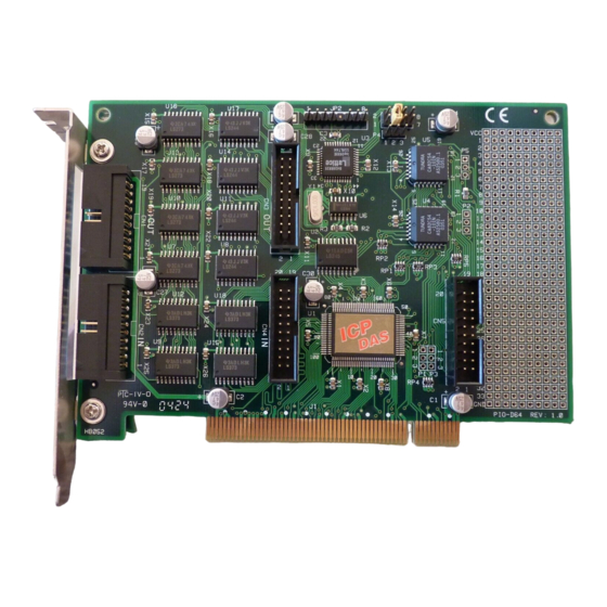
ГК Атлант Инжиниринг – официальный представитель в РФ и СНГ +7(495)109-02-08 sales@bbrc.ru www.bbrc.ru 2. Hardware configuration Board Layout Figure 2.1 PIO-D64/PIO-D64U User’s Manual ( Ver.1.6, Mar. 2015, PMH-007-16 ) ----- 9... -
Page 10: I/O Port Location
ГК Атлант Инжиниринг – официальный представитель в РФ и СНГ +7(495)109-02-08 sales@bbrc.ru www.bbrc.ru I/O Port Location There are two 16-bit digital input ports and two 16-bit digital output ports on the PIO-D64/PIO-D64U.These I/O port locations are given as below and illustrated in Figure 2.1. Connector of Description... - Page 11 ГК Атлант Инжиниринг – официальный представитель в РФ и СНГ +7(495)109-02-08 sales@bbrc.ru www.bbrc.ru All signals are TTL compatible. PIO-D64/PIO-D64U User’s Manual ( Ver.1.6, Mar. 2015, PMH-007-16 ) ----- 11...
-
Page 12: I/O Operation
3.1.1. Note that the RESET\ is in Low-state in order to clear all DO states to low level signal. The detail block diagram of DO function is represented as Figure 2.2. Figure 2.2: Block diagram of DO function PIO-D64/PIO-D64U User’s Manual ( Ver.1.6, Mar. 2015, PMH-007-16 ) ----- 12... -
Page 13: Di Port Architecture (Cn2 & Cn4)
Figure 2.3, to allow user to apply the STROBE pin to latch D/I input signal. If no signal is connected to strobe pin, the input data is transparent. Figure 2.3 PIO-D64/PIO-D64U User’s Manual ( Ver.1.6, Mar. 2015, PMH-007-16 ) ----- 13... -
Page 14: Timer/ Counter Architecture
ГК Атлант Инжиниринг – официальный представитель в РФ и СНГ +7(495)109-02-08 sales@bbrc.ru www.bbrc.ru Timer/ Counter Architecture PIO-D64/PIO-D64U has two timer/counter chips, 8254. The first 8254 chip is used as general purpose timer/counter, as shown in Figure 2.4. The pin assignment is presented in Sec.2.3. - Page 15 ГК Атлант Инжиниринг – официальный представитель в РФ и СНГ +7(495)109-02-08 sales@bbrc.ru www.bbrc.ru Figure 2.5 Note: Refer to Sec.2.3 for more information about pin assignment. Refer to Sec.2.7 for more information about operation of interrupt. PIO-D64/PIO-D64U User’s Manual ( Ver.1.6, Mar. 2015, PMH-007-16 ) ----- 15...
-
Page 16: Clock Source
ГК Атлант Инжиниринг – официальный представитель в РФ и СНГ +7(495)109-02-08 sales@bbrc.ru www.bbrc.ru Clock source The PIO-D64 / PIO-D64U provides wide range clock source as below table. By jumper setting of JP1, user can select suitable clock output from the corresponding P4 soldering pad. -
Page 17: Interrupt Operation
This hold_time is different for different operating system. The hold_time can be as short as micro-second or as long as second. In general, 20 ms is enough for all operating system. PIO-D64/PIO-D64U User’s Manual ( Ver.1.6, Mar. 2015, PMH-007-16 ) ----- 17... -
Page 18: Interrupt Block Diagram Of Pio-D64/Pio-D64U
The interrupt output signal of PIO-D64/PIO-D64U, INT\, is level-trigger & Active_Low. If the INT\ generates a low-pulse, the PIO-D64/PIO-D64U will interrupt the PC once a time. If the INT\ is fixed in low level, the PIO-D64/PIO- D64U will interrupt the PC continuously. Therefore, for the normal application, the INT_CHAN_0/1/2 must be controlled in a pulse_type signals. -
Page 19: Int_Chan_0
Figure 2.7 and Sec. 3.1.6) INV0=0 INT_CHAN_0=inverted state of EXTIRQ INV0=1 INT_CHAN_0=non-inverted state of EXTIRQ NOTE: Refer to DEMO3.C in DOS operating system for more information. PIO-D64/PIO-D64U User’s Manual ( Ver.1.6, Mar. 2015, PMH-007-16 ) ----- 19... -
Page 20: Int_Chan_1
Figure 2.8 and Sec. 3.1.6) INV1=0 INT_CHAN_1=inverted state of EVTIRQ INV1=1 INT_CHAN_1=non-inverted state of EVTIRQ NOTE: Refer to DEMO4.C in DOS operating system for more information. PIO-D64/PIO-D64U User’s Manual ( Ver.1.6, Mar. 2015, PMH-007-16 ) ----- 20... -
Page 21: Int_Chan_2
Figure 2.9 and Sec. 3.1.6) INV2=0 INT_CHAN_2=inverted state of TMRIRQ INV2=1 INT_CHAN_2=non-inverted state of TMRIRQ NOTE: Refer to DEMO5.C in DOS operating system for more information. PIO-D64/PIO-D64U User’s Manual ( Ver.1.6, Mar. 2015, PMH-007-16 ) ----- 21... -
Page 22: Daughter Boards
The detail function block diagram is shown as Figure 2.10. AC or DC Signal 0 V to 24 V Figure 2.10 PIO-D64/PIO-D64U User’s Manual ( Ver.1.6, Mar. 2015, PMH-007-16 ) ----- 22... -
Page 23: Db-16R Relay Board
The detail function block diagram is shown as Figure 2.11. Note: Channel: 16 From C Relay Relay: Switching up to 0.5 A at 110 V or 1 A at 24 V Figure 2.11 PIO-D64/PIO-D64U User’s Manual ( Ver.1.6, Mar. 2015, PMH-007-16 ) ----- 23... -
Page 24: Db-24Prd, Db-24Por, Db-24C
PIO-D144, PIO-D96, PIO-D56, PIO-D48, PIO-D24, PIO-D168(A) Channel: 16 Form A Relays, 8 Form C Relay Relay: switching up to 5 A at 110 V / 5 A at 30 V PIO-D64/PIO-D64U User’s Manual ( Ver.1.6, Mar. 2015, PMH-007-16 ) ----- 24... -
Page 25: Daughter Board Comparison Table
50-pin flat- DB-37 header cable header header DB-37 DN-37 ADP-37/PCI ADP-50/PCI DB-24P DB-24PD DB-16P8R DB-24R DB-24RD DB-24C DB-24PR Db-24PRD DB-24POR DB-24SSR NOTE: The PIO-D64/PIO-D64U only has 20-pin flat-cable header. PIO-D64/PIO-D64U User’s Manual ( Ver.1.6, Mar. 2015, PMH-007-16 ) ----- 25... -
Page 26: I/O Control Register
How to Find the I/O Address The plug & play BIOS will assign a proper I/O address to every PIO/PISO series card in the power-up stage. The IDs of PIO-D64 card are given as follows: < REV 1.0 > : <... - Page 27 Note: If the board has different version, it may has different Sub IDs. But no matter which version of the board you select, we offer the same function calls. PIO-D64/PIO-D64U User’s Manual ( Ver.1.6, Mar. 2015, PMH-007-16 ) ----- 27...
-
Page 28: The Assignment Of I/O Address
The records may be as follows: Table 3-2 PC’s PCI slot WslotBus WslotDevice Slot_1 0x07 Slot_2 0x08 Slot_3 0x09 Slot_4 0x0A PCI-BRIDGE Slot_5 0x0A Slot_6 0x08 Slot_7 0x09 Slot_8 0x07 PIO-D64/PIO-D64U User’s Manual ( Ver.1.6, Mar. 2015, PMH-007-16 ) ----- 28... - Page 29 & wSlotDevice in step1 and step2. Note that normally the card installed in slot 0 is the card0 and card installed in slot1 is the card1 for PIO/PISO series cards. PIO-D64/PIO-D64U User’s Manual ( Ver.1.6, Mar. 2015, PMH-007-16 ) ----- 29...
-
Page 30: The I/O Address Map
I/O address by user. The Plug & Play BIOS will assign proper I/O address to each PIO/PISO series card very well. The I/O addresses of PIO-D64/PIO-D64U are given as follows, which are based on the base address of each card. -
Page 31: Reset\ Controlregister
Note. Refer to Sec. 3.1 for more information about wBase. When the Aux? is used as D/O, the output state is controlled by this register. This register is designed for feature extension, so don’t control this register now. PIO-D64/PIO-D64U User’s Manual ( Ver.1.6, Mar. 2015, PMH-007-16 ) ----- 31... -
Page 32: Int Mask Control Register
for INT_CHAN_0 only DEMO3.C of DOS for INT_CHAN_1 only DEMO4.C of DOS for INT_CHAN_2 only DEMO5.C of DOS for INT_CHAN_1 and INT_CHAN_2 DEMO6.C of DOS PIO-D64/PIO-D64U User’s Manual ( Ver.1.6, Mar. 2015, PMH-007-16 ) ----- 32... -
Page 33: Aux Status Register
/* select the non-inverted input from the others outportb(wBase+0x2a,0x0c); /* select the inverted input of INT_CHAN_0 & INT_CHAN_1 /* select the non-inverted input from the others Refer to DEMO6.C of DOS for more information. PIO-D64/PIO-D64U User’s Manual ( Ver.1.6, Mar. 2015, PMH-007-16 ) ----- 33... -
Page 34: Read/Write 8254
Bit 4 Bit 3 Bit 2 Bit 1 Bit 0 wCardID = inportb(wBase+0xF4); /* read Card ID Note: The Card ID function supports the model: PIO-D64U (Ver1.0 or above) PIO-D64/PIO-D64U User’s Manual ( Ver.1.6, Mar. 2015, PMH-007-16 ) ----- 34... -
Page 35: Software Installation
ГК Атлант Инжиниринг – официальный представитель в РФ и СНГ +7(495)109-02-08 sales@bbrc.ru www.bbrc.ru 4. Software Installation The PIO-D64 / PIO-D64U can be used in DOS and Windows 98/Me/NT/2K and 32-bit Windows XP/2003/Vista/7. For Windows operating system, the recommended installation steps are given in Sec 4.1 ~ 4.2 4.1 Software Installing Procedure... -
Page 36: Pnp Driver Installation
PIODIO.inf to install hardware driver on the computer. If user has trouble in the process, please refer to PnPinstall.pdf for more information. PIO-D64/PIO-D64U User’s Manual ( Ver.1.6, Mar. 2015, PMH-007-16 ) ----- 36... -
Page 37: Dll Function Description
PIO.sys to access the hardware system. User's Application Function Call into DLLs Development DLLs Toolkit Services Call into Kernel-Mode .VXDs, .SYSs (Device Driver) Device Control Hardware Devices Figure 5.1 PIO-D64/PIO-D64U User’s Manual ( Ver.1.6, Mar. 2015, PMH-007-16 ) ----- 37... -
Page 38: Table Of Errorcode And Errorstring
The flag queue is empty PIODIO_ActiveFlagEndOfQueue Function Descriptions All of the functions provided for PIO-D64/PIO-D64U are listed as below and the detail information for every function will be presented in the following section. However, in order to make the description simplify and clearly, the attribute of the input and output parameter of the function are indicated as [input] and [output] respectively, as shown in following table. -
Page 39: Functions Of Test
PIODIO_FloatSub(float fA, float fB) Parameter: : [Input] 4 bytes floating point value : [Input] 4 bytes floating point value The value of fA - fB Return: PIO-D64/PIO-D64U User’s Manual ( Ver.1.6, Mar. 2015, PMH-007-16 ) ----- 39... -
Page 40: Digital I/O Functions
[Input] I/O port addresses, please refer to function PIODIO_GetConfigAddressSpace(). Only the low WORD is valid. Return: 16 bits data with the leading 8 bits are all 0. (Only the low BYTE is valid.) PIO-D64/PIO-D64U User’s Manual ( Ver.1.6, Mar. 2015, PMH-007-16 ) ----- 40... -
Page 41: Piodio_Outputword
Parameter : wPortAddr : [Input] I/O port addresses, please refer to function PIODIO_GetConfigAddressSpace(). Only the low WORD is valid. Return: 16-bit data. Only the low WORD is valid. PIO-D64/PIO-D64U User’s Manual ( Ver.1.6, Mar. 2015, PMH-007-16 ) ----- 41... -
Page 42: Driver Relative Functions
This function must be called once before applying other PIODIO functions. Syntax : WORD PIODIO_DriverInit(); Parameter : None Return: Please refer to "Section 5.1 Error Code". PIO-D64/PIO-D64U User’s Manual ( Ver.1.6, Mar. 2015, PMH-007-16 ) ----- 42... -
Page 43: Piodio_Searchcard
This subroutine closes the PIODIO Driver and releases the resource from computer device resource. This function must be called once before exiting the user's application. Syntax : void PIODIO_DriverClose(); Parameter : None Return: None PIO-D64/PIO-D64U User’s Manual ( Ver.1.6, Mar. 2015, PMH-007-16 ) ----- 43... -
Page 44: Piodio_Getconfigaddressspace
: [Output] Sub Device ID. wSubAux : [Output] Sub Aux ID. wSlotBus : [Output] Slot Bus number. wSlotDevice : [Output] Slot Device ID. Return: Please refer to "Section 5.1 Error Code". PIO-D64/PIO-D64U User’s Manual ( Ver.1.6, Mar. 2015, PMH-007-16 ) ----- 44... -
Page 45: Interrupt Function
Syntax : WORD PIODIO_IntGetCount(DWORD *dwIntCount); Parameter: dwIntCount : [Output] Address of dwIntCount, which will stores the counter value of interrupt. Return: Please refer to "Section 5.1 Error Code". PIO-D64/PIO-D64U User’s Manual ( Ver.1.6, Mar. 2015, PMH-007-16 ) ----- 45... -
Page 46: Piodio_Intinstall
5.6.4 PIODIO_IntRemove Description: This subroutine removes the IRQ service routine. Syntax: WORD PIODIO_IntRemove( void ); Parameter: None Return: Please refer to "Section 5.1 Error Code". PIO-D64/PIO-D64U User’s Manual ( Ver.1.6, Mar. 2015, PMH-007-16 ) ----- 46... -
Page 47: Architecture Of Interrupt Mode
ГК Атлант Инжиниринг – официальный представитель в РФ и СНГ +7(495)109-02-08 sales@bbrc.ru www.bbrc.ru 5.6.5 Architecture of Interrupt mode Figure 5.2 PIO-D64/PIO-D64U User’s Manual ( Ver.1.6, Mar. 2015, PMH-007-16 ) ----- 47... -
Page 48: Counter Function
: [Input] The 8254 Counter-Number: 0 to 5. (0 to 2: Chip-0, 3 to 5: Chip-1) wCounterMode: [Input]The 8254 Counter-Mode: 0 to 5. Return: 16 bits counter's value. (Only the lower WORD is valid.) PIO-D64/PIO-D64U User’s Manual ( Ver.1.6, Mar. 2015, PMH-007-16 ) ----- 48... -
Page 49: Piod64_Setcountera
(0 to 2: Chip-0, 3 to 5: Chip-1) wCounterMode : [Input] The 8254 Counter-Mode: 0 to 5. Return: Returns the 16 bits counter's value. (Only the lower WORD is valid.) PIO-D64/PIO-D64U User’s Manual ( Ver.1.6, Mar. 2015, PMH-007-16 ) ----- 49... -
Page 50: Program Architecture
5.7.5 Program Architecture Initialize the Device-Driver PIODIO_DriverInit() Enable All DI/DO …. Access/Control the Device PIODIO_InputByte( … ) …….. Access/Control the Device …….. PIODIO_OutputByte(…) ….. Close the Device-Driver Figure 5.3 PIO-D64/PIO-D64U User’s Manual ( Ver.1.6, Mar. 2015, PMH-007-16 ) ----- 50... -
Page 51: Demo Programs For Windows
Header file |--\PIODIO.H Linkage library for VC \ PIODIO.LIB The list of demo programs : : Digital Input / Output. : Interrupt of EXTIRQ. Counter : Counter0. PIO-D64/PIO-D64U User’s Manual ( Ver.1.6, Mar. 2015, PMH-007-16 ) ----- 51... -
Page 52: Digital Input/Output
CN2/CN4 and CN1/CN3. Figure 6.1 6.2 Interrupt of EXTIRQ This demo program uses EXTIRQ as interrupt source. Then DO0 output a high and low signal repeatedly to trigger the interrupt source. PIO-D64/PIO-D64U User’s Manual ( Ver.1.6, Mar. 2015, PMH-007-16 ) ----- 52... -
Page 53: Counter Function Of Counter0
6.3 Counter Function of counter0 This demo program uses internal clock to test counter0 function. User can select clock suitable clock output from the corresponding P4 soldering pad. Figure 6.3 PIO-D64/PIO-D64U User’s Manual ( Ver.1.6, Mar. 2015, PMH-007-16 ) ----- 53... -
Page 54: Appendix
DEMO3.C : Use external int. to measure pulse width(high level) DEMO4.C : Use EVTIRQ to count event DEMO5.C : Use TMRIRQ to generate 0.5 Hz squa. DEMO6.C : Use TMRIRQ to generate 0.5 Hz squa. EVTIRQ to count PIO-D64/PIO-D64U User’s Manual ( Ver.1.6, Mar. 2015, PMH-007-16 ) ----- 54... -
Page 55: Dos Lib Function
: [Input] SubVendor ID of the board wSubDevice : [Input] SubDevice ID of the board wSubAux : [Input] SubAux ID of the board Return: Please refer to " Table A.1". PIO-D64/PIO-D64U User’s Manual ( Ver.1.6, Mar. 2015, PMH-007-16 ) ----- 55... - Page 56 : [Output] Sub Device ID. wSubAux : [Output] Sub Aux ID. wSlotBus : [Output] Slot Bus number. wSlotDevice : [Output] Slot Device ID. Return: Please refer to " Table A.1". PIO-D64/PIO-D64U User’s Manual ( Ver.1.6, Mar. 2015, PMH-007-16 ) ----- 56...
- Page 57 : [Input] SubVendor ID of the board wSubDevice : [Input] SubDevice ID of the board wSubAux : [Input] SubAux ID of the board. Return: Please refer to " Table A.1". PIO-D64/PIO-D64U User’s Manual ( Ver.1.6, Mar. 2015, PMH-007-16 ) ----- 57...
Need help?
Do you have a question about the PIO-D64 and is the answer not in the manual?
Questions and answers