Table of Contents
Advertisement
Quick Links
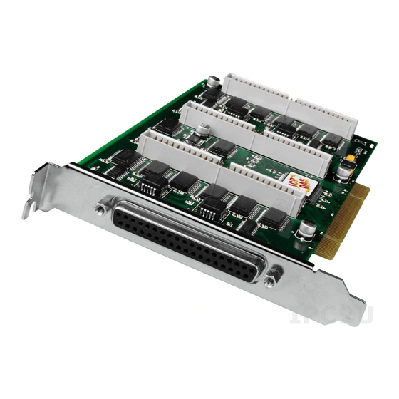
PIO-D96 Series Card
User Manual
96-channel DIO board
S
UPPORTS
Board includes PIO-D96, PIO-D96U, PIO-D96SU and PEX-D96S.
W
ARRANTY
All products manufactured by ICP DAS are warranted against defective materials
for a period of one year from the date of delivery to the original purchaser.
W
ARNING
ICP DAS assumes no liability for damages consequent to the use of this product.
ICP DAS reserves the right to change this manual at any time without notice. The
information furnished by ICP DAS is believed to be accurate and reliable. However,
no responsibility is assumed by ICP DAS for its use, nor for any infringements of
patents or other rights of third parties resulting from its use.
C
OPYRIGHT
Copyright © 2018 by ICP DAS. All rights are reserved.
T
RADEMARK
Names are used for identification only and may be registered trademarks of their
respective companies.
C
US
ONTACT
If you have any question, please feel to contact us. We will give you quick
response within 2 workdays.
Email: service@icpdas.com, service.icpdas@gmail.com
Version 2.3, Jun. 2018
Advertisement
Table of Contents

Subscribe to Our Youtube Channel
Related Manuals for ICP DAS USA PIO-D96


Summary of Contents for ICP DAS USA PIO-D96
- Page 1 96-channel DIO board Version 2.3, Jun. 2018 UPPORTS Board includes PIO-D96, PIO-D96U, PIO-D96SU and PEX-D96S. ARRANTY All products manufactured by ICP DAS are warranted against defective materials for a period of one year from the date of delivery to the original purchaser.
-
Page 2: Table Of Contents
AYOUT I/O P ..............................7 OCATION ID S ............................. 9 WITCH ..............................10 SSIGNMENTS .............................. 11 2.4.1 PIO-D96 and PIO-D96U ..........................11 I/O O 2.4.2 PIO-D96SU and PEX-D96S ......................... 12 NABLE PERATION DI/DO A ............................. 13 RCHITECTURE ............................14 NTERRUPT PERATION ............................ - Page 3 PIO-D96 Series Card 96-channel DIO Board 6.3.2 AUX Control Register ........................... 41 6.3.3 AUX Data Register ............................42 6.3.4 INT Mask Control Register ........................... 42 6.3.5 Aux Status Register ............................. 43 6.3.6 Interrupt Polarity Register ........................... 43 6.3.7 I/O Selection Control Register ........................44 6.3.8...
-
Page 4: Packing List
PIO-D96 Series Card 96-channel DIO Board Packing List The shipping package includes the following items: One PIO-D96 Series card as follows: PIO-D96SU PIO-D96/D96U PEX-D96S One printed Quick Start Guide One Software Utility CD Note: If any of these items is missing or damaged, contact the dealer from whom you purchased the product. Save the shipping materials and carton in case you need to ship or store the product in the future. -
Page 5: Introduction
1. Introduction The PEX-D96S and PIO-D96U/D96SU cards are the new generation product that ICP DAS provides to meet RoHS compliance requirement, and is designed as an easy replacement for the PIO-D96, without requiring any modification to the software or the driver. -
Page 6: Features
Card ID function for PIO-D96U/D96SU and PEX-D96S Pull-high/low jumpers for DI channels for PIO-D96U/D96SU and PEX-D96S PIO-D96/D96U: one DB37 connector and three 50-pin box headers PIO-D96SU/PEX-D96S: one SCSI II 100-pin connector Buffer output for higher driving capability ... -
Page 7: Specifications
PIO-D96 Series Card 96-channel DIO Board 1.2 Specifications Model Name PEX-D96S PIO-D96SU PIO-D96U PIO-D96 (Phased-out) Programmable Digital I/O Channels Digital Input Compatibility 5 V/COMS 5 V/TTL Logic 0: 0.8 V max. Input Voltage Logic 1: 2.0 V min. Response Speed... -
Page 8: Hardware Configuration
PIO-D96 Series Card 96-channel DIO Board 2. Hardware Configuration 2.1 Board Layout PIO-D96/PIO-D96U: Note: The JPx default settings: JP2/3/4/5/6/7/9/10/11/12/13 = 1-2 short = Pull-Low refer to Section 2.2 “I/O Port Location” for more detailed about DI pull-high/low information. User Manual, Ver. 2.3, Jun. 2018, PMH-008-23 Page: 7... - Page 9 PIO-D96 Series Card 96-channel DIO Board PIO-D96SU/PEX-D96S: Note: The JPx default settings: JP2/3/4/5/6/7/9/10/11/12/13 = 1-2 short = Pull-Low refer to Section 2.2 “I/O Port Location” for more detailed about DI pull-high/low information. User Manual, Ver. 2.3, Jun. 2018, PMH-008-23 Page: 8...
-
Page 10: I/O Port Location
2.2 I/O Port Location There are twelve 8-bit I/O ports in the PIO-D96 series card. Each I/O port can be programmed as a DI or DO port. When the PC is first powered-on or reset all the ports are configured as DI ports. -
Page 11: Card Id Switch
PIO-D96 Series Card 96-channel DIO Board 2.3 Card ID Switch The PIO-D96U/D96SU and PEX-D96S has a Card ID switch (SW1) with which users can recognize the board by the ID via software when using two or more PIO-D96U/D96SU and PEX-D96S cards in one computer. -
Page 12: Pin Assignments
PIO-D96 Series Card 96-channel DIO Board 2.4 Pin Assignments 2.4.1 PIO-D96 and PIO-D96U CON1: 37-pin D-type female connector (for Port0, Port1, Port2). CN1/CN2/CN3: 50-pin flat-cable connector (for Port3 to Port11). Figure 2-1 User Manual, Ver. 2.3, Jun. 2018, PMH-008-23 Page: 11... -
Page 13: Pio-D96Su And Pex-D96S
PIO-D96 Series Card 96-channel DIO Board 2.4.2 PIO-D96SU and PEX-D96S CON1: 100-pin SCSI II connector (for Port0 to Port11). Figure 2-2 User Manual, Ver. 2.3, Jun. 2018, PMH-008-23 Page: 12... - Page 14 PIO-D96 Series Card 96-channel DIO Board 2.5 Enable I/O Operation When the PC is first turned on, all operations involved with Digital I/O channels are disabled. Note that the Digital I/O channel of each port is enabled or disabled by the RESET\ signal, refer to Section 6.3.1 “REST\ Control Register”...
-
Page 15: Di/Do Architecture
96-channel DIO Board 2.6 DI/DO Architecture The Digital I/O control architecture for the PIO-D96 series card is demonstrated in the figure below. The operation method used for the control signal is presented below. RESET\ is in the Low-state all DI/DO operation is disabled ... -
Page 16: Interrupt Operation
Section 2.4 “Pin Assignments” for P2C0/P5C0/P8C0/P11C0 location. The interrupt of PIO-D96 series card is level-trigger and Active_High. The interrupt signal can be programmable as inverted or non-inverted. The procedures for how to configure the interrupt signal source are given as follows: 1. -
Page 17: Hardware Installation
Windows 2000 or Windows XP, etc. Installing the driver first helps reduce the time required for installation and restarting the computer. To install your PIO-D96 series card, follow the procedure described below: Step 1: Install the driver for your board on Host computer. - Page 18 PIO-D96 Series Card 96-channel DIO Board Step 3: Shut down and switch off the power to the computer, and then disconnect the power supply. Step 4: Remove the cover from the computer. Step 5: Select a vacant PCI/PCI Express slot.
- Page 19 PIO-D96 Series Card 96-channel DIO Board Step 6: Unscrew and remove the PCI slot cover from the computer case. Step 7: Remove the connector cover from your board. Step 8: Carefully insert your board into the PCI/PCI Express slot by gently pushing down on both sides of the board until it slides into the PCI connector.
- Page 20 PIO-D96 Series Card 96-channel DIO Board Step 9: Confirm that the board is correctly inserted in the motherboard, and then secure your board in place using the retaining screw that was removed in Step 6. Step 10: Replace the covers on the computer.
-
Page 21: Software Installation
This chapter provides a detailed description of the process for installing the PIO-D96 series driver and how to verify whether the PIO-D96 was properly installed. PIO-D96 series card can be used on DOS, Linux and 32/64-bit XP/2003/2008/7/8/10 based systems, and the drivers are fully Plug and Play (PnP) compliant for easy installation. - Page 22 PIO-D96 Series Card 96-channel DIO Board Step 2: When the “Welcome to the ICP DAS UniDAQ Driver Setup Wizard” screen is displayed, click the “Next>” button to start the installation. Step 3: On the “Information” screen, verify that the DAQ board is included in the list of supported devices, then click the “Next>”...
- Page 23 PIO-D96 Series Card 96-channel DIO Board PIO-DIO Series Classic Driver (Recommended to install this driver for have been used PIO-DIO series boards of regular user) Windows 95/98/ME, Windows NT, Windows 2000, 32-bit Windows XP, 32-bit Windows 2003, 32-bit Windows Vista, 32-bit Windows 7, 32-bit Windows 8, , 32-bit Windows 10 PIO-DIO Series Classic Driver(PIO_DIO_Win__vxxx.exe)
-
Page 24: Pnp Driver Installation
Correctly shut down and power off your computer and disconnect the power supply, and then install your board into the computer. For detailed information about the hardware installation of PIO-D96 series board, refer to Chapter 3 “Hardware Installation”. Step 2: Power on the computer and complete the Plug and Play installation. - Page 25 PIO-D96 Series Card 96-channel DIO Board Step 4: Click the “Finish” button. Step 5: Windows pops up “Found New Hardware” dialog box again. User Manual, Ver. 2.3, Jun. 2018, PMH-008-23 Page: 24...
-
Page 26: Verifying The Installation
PIO-D96 Series Card 96-channel DIO Board 4.3 Verifying the Installation To verify that the driver was correctly installed, use the Windows Device Manager to view and update the device drivers installed on the computer, and to ensure that the hardware is operating correctly. - Page 27 PIO-D96 Series Card 96-channel DIO Board Windows 2000/XP Step 1: Click the “Start” button and then point to “Settings” and click “Control Panel”. Double-click the “System” icon to open the “System Properties” dialog box. Step 2: Click the “Hardware” tab and then click the “Device Manager” button.
- Page 28 PIO-D96 Series Card 96-channel DIO Board Windows 7/10 Step 1: Click the “Start” button, and then click “Control Panel”. Step 2: Click “System and Maintenance”, and then click “Device Manager”. Alternatively, Step 1: Click the “Start” button. Step 2: In the Search field, type Device Manager and then press Enter.
-
Page 29: Check That The Installation
PIO-D96 Series Card 96-channel DIO Board 4.3.2 Check that the Installation Check that the PIO-D96 series board is correctly listed in the Device Manager window, as illustrated below. User Manual, Ver. 2.3, Jun. 2018, PMH-008-23 Page: 28... -
Page 30: Board Testing
This chapter provides detailed information about the “Self-Test” process, which is used to confirm that the PIO-D96 series board is operating correctly. Before beginning the “Self-Test” process, ensure that both the hardware and driver installation procedures are fully completed. For detailed information about the hardware and driver installation, refer to Chapter 3 “Hardware Installation”... -
Page 31: Pio-D96Su/Pex-D96S
PIO-D96 Series Card 96-channel DIO Board Step 2: Connect the Port0 (PA0 ~ PA7) with Port1 (PB0 ~ PB7). 20 21 22 23 24 25 26 27 28 29 30 31 32 33 34 35 36 37 9 10 11 13 14 15 16 17 18 19 5.1.2 PIO-D96SU/PEX-D96S... - Page 32 20 21 22 23 24 25 NG 5.2 Launch the Test Program The following example use UniDAQ driver to perform self-test. If you install the PIO-DIO series classic driver, refer to Quick Start Guide of the PIO-D96 series (http://ftp.icpdas.com/pub/cd/iocard/pci/napdos/pci/pio-dio/manual/quickstart/classic/) to execute the self-test.
- Page 33 Step 3: Click the “TEST” button to start the test. Note: The PEX-D96S, PIO-D96SU and PIO-D96U software is fully compatible with the PIO-D96 series software. Step 4: Check the results of the Digital Input and Digital Output functions test. 1. Click the “Digital Output” tab.
- Page 34 PIO-D96 Series Card 96-channel DIO Board 4. Click the “Digital Input” tab. 5. Select “Port 0” from the “Port Number” drop-down menu. 6. The DI indicators will turn red when the corresponding DO channels 0, 2, 4 and 6 are ON.
-
Page 35: I/O Control Register
During the power-on stage, the Plug and Play BIOS will assign an appropriate I/O address to each PIO-D96 series card installed in the system. Each board includes four fixed ID numbers that are used to identify the board, and are indicated below:... - Page 36 PIO-D96 Series Card 96-channel DIO Board We provide all necessary functions as follows: 1. PIO_DriverInit(&wBoard, wSubVendor, wSubDevice, wSubAux) 2. PIO_GetConfigAddressSpace(wBoardNo,*wBase,*wIrq, *wSubVendor,*wSubDevice, *wSubAux, *wSlotBus, *wSlotDevice) 3. Show_PIO_PISO(wSubVendor, wSubDevice, wSubAux) All functions are defined in PIODIO.H. Refer to Section 6.3 “The I/O Address Map”...
- Page 37 PIO-D96 Series Card 96-channel DIO Board PIO_PISO.EXE Utility The PIO_PISO.EXE utility is valid for all PIO/PISO cards. This program shows all PCI hardware ID regarding the PIO and PISO series DAQ cards. It is useful to test if the card Plug & Play successfully when the computer bootup.
- Page 38 PIO-D96 Series Card 96-channel DIO Board For DOS The PIO_PISO.EXE for DOS is contained in: CD:\NAPDOS\PCI\Utility\DOS\ http://ftp.icpdas.com/pub/cd/iocard/pci/napdos/pci/utility/dos/ The PIO_PISO program source is given as follows: /* -------------------------------------------------------------- */ /* Find all PIO_PISO series cards in this PC system */ /* step 1 : plug all PIO_PISO cards into PC /* step 2 : run PIO_PISO.EXE...
-
Page 39: The Assignment Of I/O Address
Then record the “wSlotBus1” and “wSlotDevice1” information. Step 3: Remove all PIO-D96 series boards from the PC. Step 4: Install one PIO-D96 series into the PC’s PCI_slot2 and run PIO_PISO.EXE. Then record the “wSlotBus2” and “wSlotDevice2” information. Step 5: Repeat Steps(3) and (4) for every PCI_slot and record all information from “wSlotBus”... - Page 40 PIO-D96 Series Card 96-channel DIO Board The above procedure will record all the “wSlotBus” and “wSlotBus” information on a PC. These values will be mapped to this PC’s physical slot and this mapping will not be changed for any PIO/PISO cards. Therefore, this information can be used to identify the specified PIO/PISO card by following steps: Step1: Using the “wSlotBus”...
-
Page 41: The I/O Address Map
The Plug and Play BIOS will assign an appropriate I/O address to each PIO/PISO series card. The I/O addresses of the PIO-D96 series card are as follows, and are based on the base address of each card. -
Page 42: Reset\ Control Register
PIO-D96 Series Card 96-channel DIO Board 6.3.1 RESET\ Control Register (Write): wBase+0 Bit 7 Bit 6 Bit 5 Bit 4 Bit 3 Bit 2 Bit 1 Bit 0 Reserved Reserved Reserved Reserved Reserved Reserved Reserved RESET\ When the PC’s power is first turned on, RESET\ signal is in a Low-state. This will disable all DI/O operations. -
Page 43: Aux Data Register
PIO-D96 Series Card 96-channel DIO Board 6.3.3 AUX Data Register (Read/Write): wBase+3 Bit 7 Bit 6 Bit 5 Bit 4 Bit 3 Bit 2 Bit 1 Bit 0 Aux7 Aux6 Aux5 Aux4 Aux3 Aux2 Aux1 Aux0 When the Aux is used for DO, the output state is controlled by this register. This register is designed for feature extension. -
Page 44: Aux Status Register
PIO-D96 Series Card 96-channel DIO Board 6.3.5 Aux Status Register (Read/Write): wBase+7 Bit 7 Bit 6 Bit 5 Bit 4 Bit 3 Bit 2 Bit 1 Bit 0 Aux7 Aux6 Aux5 Aux4 Aux3 Aux2 Aux1 Aux0 Aux0=P2C0, Aux1=P5C0, Aux2=P8C0, Aux3=P11C0, Aux7~4=Aux-ID. Refer to DEMO5.C for more information. -
Page 45: I/O Selection Control Register
Port11 Port10 Port9 These registers provide the function for configuration digital input/output port of the PIO-D96 Note that all ports are used series Card. Every I/O port can be programmed to be a DI or a DO port. as D/I ports when the PC is first turned on. -
Page 46: Card Id Register
Bit 1 Bit 0 There are 12 8-bit I/O ports in the PIO-D96 series card. Every I/O port can be configured as DI or DO Note that all port. User can send/receive digital data to/from this register for digital input or output. -
Page 47: Demo Programs
CSharp2005 for C#.NET2005 PIODIO.vb Visual Basic Source files PIODIO.cs Visual C# Source files For detailed information about the DLL function of the PIO-D96 series, refer to PIO-DIO DLL Software Manual (CD:\NAPDOS\PCI\PIO-DIO\Manual\) User Manual, Ver. 2.3, Jun. 2018, PMH-008-23 Page: 46... - Page 48 PIO-D96 Series Card 96-channel DIO Board Demo Program for UniDAQ SDK Driver The demo program is contained in: CD:\NAPDOS\PCI\UniDAQ\DLL\Demo\ http://ftp.icpdas.com/pub/cd/iocard/pci/napdos/pci/unidaq/dll/demo/ BCB6 for Borland C Builder 6 Delphi6 for Delphi 6 UniDAQ.H Header files UniDAQ.PAS Declaration files UniDAQ.LIB ...
-
Page 49: Demo Program For Dos
PIO-D96 Series Card 96-channel DIO Board 7.2 Demo Program for DOS The demo program is contained in: CD:\NAPDOS\PCI\PIO-DIO\DOS\d96\ http://ftp.icpdas.com/pub/cd/iocard/pci/napdos/pci/pio-dio/dos/d96/ \TC\*.* for Turbo C 2.xx or above \MSC\*.* for MSC 5.xx or above \BC\*.* for BC 3.xx or above \TC\LIB\*.*... -
Page 50: Appendix: Daughter Board
DN-50 Use a 37-pin cable (e.g. CA-3710, etc.) to connect to CON1 of the PIO-D96/D96U by DN-37, and then use a 50-pin cable (e.g. CA-5002, etc.) to connect to CN2/CN2/CN3 by DN-50. DN-37... -
Page 51: A2. Db-8125
The DB-8125 is a general purpose screw terminal board. It is designed for easy wire connection. The DB-8125 consists of one DB-37 and two 20-pin flat-cable headers. Use a 37-pin cable (e.g. CA-3710, etc.) to connect DB-8125 to CON1 of the PIO-D96(U). DB-8125 A3. ADP-37/PCI and ADP-50/PCI The ADP-37/PCI and ADP-50/PCI are extender for the 50-pin header. -
Page 52: A4. Db-24P And Db-24Rd Relay Board
PIO-D96 Series Card 96-channel DIO Board A4. DB-24P and DB-24PD Isolated Input Board The DB-24P is a 24-channel isolated digital input daughter board. The optically isolated inputs of the DB-24P consist of a bi-directional optocoupler with a resistor for current sensing. - Page 53 PIO-D96 Series Card 96-channel DIO Board A5. DB-24R and DB-24RD Relay Board The DB-24R, 24-channel relay output board, consists of 24 form-C relays for efficiently controlling the switch with the use of an appropriately loaded program. The relays are energized by applying a 12 V/24 V voltage...
-
Page 54: A6. Db-24Pr, Db-24Por And Db-24C
PIO-D96 Series Card 96-channel DIO Board A6. DB-24PR, DB-24POR and DB-24C DB-24PR, 24-channel power relay output board, consists of 8 Form-C and 16 form-A electromechanical DB-24C DB-24POR DB-24PR relays efficiently controlling the switch with the use of an appropriately loaded program. The contact of each relay... -
Page 55: A7. Daughter Boards Comparison Table
PIO-D96 Series Card 96-channel DIO Board A7. Daughter Boards Comparison Table Table A7-1 is the comparison table for the daughter application of PIO/PISO series cards. Table A7-1: PIO-D96 PIO-D96 PIO-D96SU I/O Card PIO-D96U PIO-D96U PEX-D96S Cable/ 20-Pin 50-Pin 37-Pin 100-Pin...
Need help?
Do you have a question about the PIO-D96 and is the answer not in the manual?
Questions and answers