Table of Contents
Advertisement
Quick Links
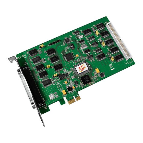
PIO-D48 Series Card
User Manual
48-channel OPTO-22 compatible DIO board
S
UPPORTS
Board includes PIO-D48, PIO-D48U, PIO-D48SU and PEX-D48.
W
ARRANTY
All products manufactured by ICP DAS are warranted against defective materials
for a period of one year from the date of delivery to the original purchaser.
W
ARNING
ICP DAS assumes no liability for damages consequent to the use of this product.
ICP DAS reserves the right to change this manual at any time without notice. The
information furnished by ICP DAS is believed to be accurate and reliable. However,
no responsibility is assumed by ICP DAS for its use, nor for any infringements of
patents or other rights of third parties resulting from its use.
C
OPYRIGHT
Copyright © 2013 by ICP DAS. All rights are reserved.
T
RADEMARK
Names are used for identification only and may be registered trademarks of their
respective companies.
C
US
ONTACT
If you have any question, please feel to contact us. We will give you quick
response within 2 workdays.
Email: service@icpdas.com, service.icpdas@gmail.com
Version 3.4, Aug. 2015
Advertisement
Table of Contents

Subscribe to Our Youtube Channel
Related Manuals for ICP DAS USA PIO-D48


Summary of Contents for ICP DAS USA PIO-D48
- Page 1 48-channel OPTO-22 compatible DIO board Version 3.4, Aug. 2015 UPPORTS Board includes PIO-D48, PIO-D48U, PIO-D48SU and PEX-D48. ARRANTY All products manufactured by ICP DAS are warranted against defective materials for a period of one year from the date of delivery to the original purchaser.
-
Page 2: Table Of Contents
NSTALLATION ..........................26 ERIFYING THE NSTALLATION 4.3.1 How do I get into Windows Device Manager? ....................26 4.3.2 Check that the Installation ..........................28 TESTING PIO-D48 SERIES CARD ......................... 29 .............................. 29 IRING ..........................31 XECUTE THE ROGRAM I/O CONTROL REGISTER ............................ 33 I/O A .......................... - Page 3 PIO-D48 Series Card 48-channel OPTO-22 Compatible DIO Board 6.3.1 RESET\ Control Register..........................38 6.3.2 INT Mask Control Register ..........................38 6.3.3 Aux Status Register ............................39 6.3.4 Interrupt Polarity Register ..........................40 6.3.5 Read/Write I/O Port ............................41 6.3.6 Read/Write 8254 .............................. 43 6.3.7 Read/Write Clock/Int Control Register ......................
-
Page 4: Introduction
1. Introduction The PIO-D48U/D48SU and PEX-D48 is the new generation product that ICP DAS provides to meet RoHS compliance requirement and is designed as completely compatible with the PIO-D48. Users can replace the PIO-D48 by the PIO-D48U/PIO-D48SU/PEX-D48 directly without software/driver modification. -
Page 5: Packing List
Six 8-bit bi-direction I/O ports Connects directly to DB-24PR, DB-24PD, DB-24RD, DB-24PRD, DB-16P8R, DB-24POR, DB-24SSR, DB-24C or any OPTO-22 Compatible daughter boards PIO-D48(U)/PEX-D48: One DB37 connector and one 50-pin box headers PIO-D48SU: One SCSI II 100-pin connector Interrupt source 4-channel ... -
Page 6: Specifications
PIO-D48 Series Card 48-channel OPTO-22 Compatible DIO Board 1.3 Specifications Model Name PIO-D48 PIO-D48U PIO-D48SU PEX-D48 Programmable Digital I/O Channels Digital Input Compatibility 5 V/TTL Logic 0: 0.8 V max. Input Voltage Logic 1: 2.0 V min. Response Speed 1 MHz... -
Page 7: Hardware Configuration
PIO-D48 Series Card 48-channel OPTO-22 Compatible DIO Board 2. Hardware Configuration 2.1 Board Layout The board layout of the PIO-D48/D48U cards are shown below: PIO-D48 PIO-D48U Only for PIO-D48U Pull-High Pull-High Pull-Low (Port3) (Port0) Pull-Low Pull-High Pull-High (Port2) (Port4) - Page 8 PIO-D48 Series Card 48-channel OPTO-22 Compatible DIO Board The board layout of the PIO-D48SU cards are shown below: (Port5) (Port4) (Port3) (Port2) (Port1) PIO-D48SU (Port0) Note: Default Setting: JP2/3/4/5/6/7=2-3 short = Pull-Low User Manual/Ver. 3.4/Aug. 2015/PMH-006-34/Page: 7...
-
Page 9: I/O Port Location
2.2 I/O Port Location There are six 8-bit I/O ports in the PIO-D48 series cards. Each I/O port can be programmed as a D/I or D/O port. When the PC is first powered-on or reset, all the ports are configured as D/I ports. -
Page 10: Card Id Switch
The PIO-D48U, PIO-D48SU and PEX-D48 has a Card ID switch (SW1) with which users can recognize the board by the ID via software when using two or more PIO-D48(S)U and PEX-D48 cards in one computer. The default Card ID is 0x0. For detail SW1 Card ID settings, please refer to Table 2.1. -
Page 11: Pin Assignments
48-channel OPTO-22 Compatible DIO Board 2.4 Pin Assignments The Pin assignments for all connectors on the PIO-D48/D48U/D48SU and PEX-D48 are represented in Figure 2-1 and Figure 2-2. All signal sources for each digital input or output pin (channel) is TTL compatible. - Page 12 PIO-D48 Series Card 48-channel OPTO-22 Compatible DIO Board Pin Assignments of the PIO-D48SU: CON1: 100-pin SCSI connector (for Port0~ Port5). Figure 2-2 User Manual/Ver. 3.4/Aug. 2015/PMH-006-34/Page: 11...
-
Page 13: Enable I/O Operation
PIO-D48 Series Card 48-channel OPTO-22 Compatible DIO Board 2.5 Enable I/O Operation When the PC is first turned on, all operations involved with digital I/O channels are disabled. Note that the digital I/O channel of each port is enabled or disabled by the RESET\ signal (Refer to Sec. -
Page 14: D/I/O Architecture
PIO-D48 Series Card 48-channel OPTO-22 Compatible DIO Board 2.6 D/I/O Architecture The digital I/O control architecture for the PIO-D48/D48U/D48SU and PEX-D48 are demonstrated in Figure 2.3. The operation method used for the control signal is presented below. RESET\ is in the Low-state all D/I/O operation is disabled ... -
Page 15: Interrupt Operation
PIO-D48 Series Card 48-channel OPTO-22 Compatible DIO Board 2.7 Interrupt Operation There are four interrupt sources in the PIO-D48/D48U/D48SU and PEX-D48. These four signals are named INT_CHAN_0, INT_CHAN_1, INT_CHAN_2 and INT_CHAN_3. Their signal sources are given as follows: INT_CHAN_0: PC3/PC7 from port-2 (Refer to Sec. -
Page 16: Interrupt Block Diagram
Active_Low. If the INT\ generates a low-pulse, the PIO-D48 series cards will interrupt the PC once per occasion. If the INT\ is fixed in low level, the PIO-D48 series cards will interrupt the PC continuously. So the INT_CHAN_0/1/2/3 must be controlled with pulse_type signals. -
Page 17: Int_Chan_0
PIO-D48 Series Card 48-channel OPTO-22 Compatible DIO Board 2.7.2 INT_CHAN_0 Figure 2-5 NT_CHAN_0 should normally be fixed in a low level state and generate a high_pulse to interrupt the PC. INT_CHAN_0 can be equal to PC3&!PC7 or be programmable as is shown below : (Refer to Sec. -
Page 18: Int_Chan_1
PIO-D48 Series Card 48-channel OPTO-22 Compatible DIO Board 2.7.3 INT_CHAN_1 Figure 2-6 INT_CHAN_1 should normally be fixed in low level state and generate a high_pulse to interrupt the PC. INT_CHAN_1 can be equal to PC3&!PC7 or be programmable as is shown below:(Refer to Sec. -
Page 19: Int_Chan_2
PIO-D48 Series Card 48-channel OPTO-22 Compatible DIO Board 2.7.4 INT_CHAN_2 Figure 2-7 INT_CHAN_2 should normally be fixed in a low-level state and generate a high_pulse to interrupt the PC. PC0 (Port-2) can be inverted/non-inverted programmable as is shown below: (Refer to Sec. -
Page 20: Int_Chan_3
PIO-D48 Series Card 48-channel OPTO-22 Compatible DIO Board 2.7.5 INT_CHAN_3 Figure 2-8 INT_CHAN_3 should normally be fixed in a low-level state and generate a high_pulse to interrupt the PC. Cin1 can be 2M/32768Hz programmable as is given below: (Refer to Sec. -
Page 21: Hardware Installation
To install your PIO-D48 series card, complete the following steps: Step 1: Installing PIO-D48 series card driver on your computer first. For detailed information about the driver installation, please... - Page 22 PIO-D48 Series Card 48-channel OPTO-22 Compatible DIO Board Step 3: Shut down and power off your computer. Step 4: Remove all covers from the computer. Step 5: Select an empty PCI/PCI Express slot. User Manual/Ver. 3.4/Aug. 2015/PMH-006-34/Page: 21...
- Page 23 48-channel OPTO-22 Compatible DIO Board Step 6: Remove the PCI/PCI Express slot cover form the PC. Step 7: Remove the connector cover form the PIO-D48 series card. Step 8: Carefully insert your PIO-D48 series card into the PCI/PCI Express slot. PEX-D48 PIO-D48 PIO-D48U PIO-D48SU...
- Page 24 PIO-D48 Series Card 48-channel OPTO-22 Compatible DIO Board Step 9: Tighten the captive Phillips screw. Confirm the PIO-D48 series card is mounted on the motherboard. Step 10: Replace the computer cover. Step 11: Power on the computer. Follow the prompt message to finish the Plug&Play steps,...
-
Page 25: Software Installation
This chapter provides a detailed description of the process for installing the PIO-D48 series driver and how to verify whether the PIO-D48 was properly installed. PIO-D48 series card can be used on DOS, Linux and Windows 98/ME/2000 and 32-/64-bit XP/2003/Vista/7/8 based systems, and the drivers are fully Plug &Play (PnP) compliant for easy installation. -
Page 26: Pnp Driver Installation
4.2 PnP Driver Installation Power off the computer and install the PIO-D48 series cards. Turn on the computer and Windows 95/98/ME/NT/2000 and 32-/64-bit Windows XP/2003/Vista/7/8 should automatically defect the new PCI device(s) and then ask for the location of the driver files for the hardware. If a problem is encountered during installation, refer to the PnPinstall.pdf file for more information. -
Page 27: Verifying The Installation
PIO-D48 Series Card 48-channel OPTO-22 Compatible DIO Board 4.3 Verifying the Installation To verify the installation, use the Windows Device Manager to view and update the device drivers installed on your computer, and check to ensure that hardware is operating correctly. The following is a description of how access the Device Manager in each of the major versions of Windows. -
Page 28: Microsoft Windows
PIO-D48 Series Card 48-channel OPTO-22 Compatible DIO Board Microsoft Windows Vista/7 Step 1: Click “Start” button, and then click “Control Panel”. Step 2: Click “System and Maintenance”, and then click “Device Manager”. Alternatively, Step 1: Click “Start” button. Step 2: In the... -
Page 29: Check That The Installation
PIO-D48 Series Card 48-channel OPTO-22 Compatible DIO Board 4.3.2 Check that the Installation Check the PIO-D48 series card which listed correctly or not, as illustrated below. Installation successful User Manual/Ver. 3.4/Aug. 2015/PMH-006-34/Page: 28... -
Page 30: Testing Pio-D48 Series Card
48-channel OPTO-22 Compatible DIO Board 5. Testing PIO-D48 Series Card This chapter can give you the detail steps about self-test. In this way, user can confirm that PIO-D48 series card well or not. Before the self-test, you must complete the hardware and driver installation. - Page 31 PIO-D48 Series Card 48-channel OPTO-22 Compatible DIO Board 2. Connect the Port0 (PA0 ~ PA7) with Port1 (PB0 ~ PB7). PIO-D48SU: 1. Use DN-100 wiring terminal board (optional) to connect the CON1 on the PIO-D48SU card. PIO-D48SU User Manual/Ver. 3.4/Aug. 2015/PMH-006-34/Page: 30...
-
Page 32: Execute The Test Program
2. Connect the Port0 (PA00 ~ PA07) with Port1 (PB00 ~ PB07). 5.2 Execute the Test Program The following example use UniDAQ driver to perform self-test. If you install the PIO-DIO series classic driver, please refer to Quick Start Guide of the PIO-D48 (http://ftp.icpdas.com/pub/cd/iocard/pci/napdos/pci/pio-dio/manual/quickstart/d48/pio-d48_quic kstart_eng.pdf) to execute the self-test. - Page 33 PIO-D48 Series Card 48-channel OPTO-22 Compatible DIO Board 4. Get DIO function test result. Click “Digital Output” item. Check channel 0, 2, 4, 6 Select the “Port 1” Click “Digital Input” item. The corresponding D/I becomes black for channel 0, 2, 4, 6 of D/O is ON.
-
Page 34: I/O Control Register
6.1 How to Find the I/O Address The plug&play BIOS will assign a proper I/O address to every PIO/PISO series card in the power-on stage. The fixed IDs for the PIO-D48 series cards are given as follows: Table 6-1: PIO-D48(U) (Rev 1.x) PIO-D48(U)/PEX-D48 (Rev 2.0 or above) - Page 35 The PIO_PISO.EXE utility program will detect and present all information for PIO/PISO cards installed in the PC, as shown in the following Figure6-1. Details of how to identify the PIO-D48 series cards of ICPDAS data acquisition boards based on the Sub-vendor,...
-
Page 36: The Assignment Of I/O Address
Step 3: Remove all PIO-D48 series boards from the PC. Step 4: Install one PIO-D48 series into the PC’s PCI_slot2 and run PIO_PISO.EXE. Then record the wSlotBus2 and wSlotDevice2 information. Step 5: Repeat Steps(3) and (4) for every PCI_slot and record all information from wSlotBus and wSlotDevice. - Page 37 PIO-D48 Series Card 48-channel OPTO-22 Compatible DIO Board The above procedure will record all the wSlotBus and wSlotDevice information on a PC. These values will be mapped to this PC’s physical slot and this mapping will not be changed for any PIO/PISO cards.
-
Page 38: The I/O Address Map
48-channel OPTO-22 Compatible DIO Board 6.3 The I/O Address Map The I/O address for PIO-D48 series cards are automatically assigned by the main board ROM BIOS. The I/O address may also be re-assigned by the user. It is strongly recommended that users do not change the I/O address. -
Page 39: Reset\ Control Register
PIO-D48 Series Card 48-channel OPTO-22 Compatible DIO Board 6.3.1 RESET\ Control Register (Read/Write): wBase+0 Bit 7 Bit 6 Bit 5 Bit 4 Bit 3 Bit 2 Bit 1 Bit 0 Reserved Reserved Reserved Reserved Reserved Reserved Reserved RESET\ When the PC’s power is first turned on, RESET\ signal is in a Low-state. This will disable all D/I/O operations. -
Page 40: Aux Status Register
PIO-D48 Series Card 48-channel OPTO-22 Compatible DIO Board For example: outportb(wBase+5,0); /*Disable all interrupt */ outportb(wBase+5,1); /* Enable interrupt of INT_CHAN_0 */ outportb(wBase+5,2); /* Enable interrupt of INT_CHAN_1 */ outportb(wBase+5,4); /* Enable interrupt of INT_CHAN_2 */ outportb(wBase+5,8); /* Enable interrupt of INT_CHAN_3 */ outportb(wBase+5,0x0f);... -
Page 41: Interrupt Polarity Register
PIO-D48 Series Card 48-channel OPTO-22 Compatible DIO Board 6.3.4 Interrupt Polarity Register (Read/Write): wBase+0x2A Bit 7 Bit 6 Bit 5 Bit 4 Bit 3 Bit 2 Bit 1 Bit 0 INV3 INV2 INV1 INV0 This register provides a function to control invert or non-invert for the interrupt signal source. A detailed application example is given below. -
Page 42: Read/Write I/O Port
PC-L These are six 8-bit I/O ports in the PIO-D48 series. Every I/O port can be programmed to be a D/I or a D/O port based on the control word settings. All six ports are configured as D/I ports when the power is first turned on. - Page 43 PIO-D48 Series Card 48-channel OPTO-22 Compatible DIO Board For example: outportb(wBase+0xcc,0x80); /* set output mode for the port-0/1/2 */ outportb(wBase+0xc0,V1); /* write to port_0 (PA) */ outportb(wBase+0xc4,V2); /* write to port_1 (PB) */ outportb(wBase+0xc8,V3); /* write to port_2 (PC) */ outportb(wBase+0xdc,0x9B);...
-
Page 44: Read/Write 8254
PIO-D48 Series Card 48-channel OPTO-22 Compatible DIO Board 6.3.6 Read/Write 8254 8254 Control Word (Read/Write): wBase+0xec Bit 7 Bit 6 Bit 5 Bit 4 Bit 3 Bit 2 Bit 1 Bit 0 Binary Count BCD Count M2 M1 M0... - Page 45 PIO-D48 Series Card 48-channel OPTO-22 Compatible DIO Board Read/Write 8-bit data of 8254 (Read/Write): wBase+0xe0/ 0xe4/ 0xe8 Bit 7 Bit 6 Bit 5 Bit 4 Bit 3 Bit 2 Bit 1 Bit 0 (Read/Write): wBase+0xec= 8254 control word (Read/Write): wBase+0xe0= 8254-counter-0...
-
Page 46: Read/Write Clock/Int Control Register
PIO-D48 Series Card 48-channel OPTO-22 Compatible DIO Board 6.3.7 Read/Write Clock/Int Control Register (Read/Write): wBase+0xf0 Bit 7 Bit 6 Bit 5 Bit 4 Bit 3 Bit 2 Bit 1 Bit 0 CTRL-D5 CTRL-D4 CTRL-D3 CTRL-D2 CTRL-D1 CTRL-D0 CTRL-D0: timer source CLK1 selection (Refer to Sec. -
Page 47: Demo Programs
CSharp2005 for C#.NET2005 PIODIO.vb Visual Basic Source files PIODIO.cs Visual C# Source files For detailed information about the DLL function of the PIO-D48 series, please refer to PIO-DIO DLL Software Manual (CD:\NAPDOS\PCI\PIO-DIO\Manual\) User Manual/Ver. 3.4/Aug. 2015/PMH-006-34/Page: 46... - Page 48 PIO-D48 Series Card 48-channel OPTO-22 Compatible DIO Board Demo Program for UniDAQ SDK Driver The demo program is contained in: CD:\NAPDOS\PCI\UniDAQ\DLL\Demo\ http://ftp.icpdas.com/pub/cd/iocard/pci/napdos/pci/unidaq/dll/demo/ BCB6 for Borland C Delphi6 for Delphi 6 Builder 6 UniDAQ.H Header files UniDAQ.PAS Declaration files UniDAQ.LIB ...
-
Page 49: Demo Program For Dos
PIO-D48 Series Card 48-channel OPTO-22 Compatible DIO Board 7.2 Demo Program for DOS The demo program is contained in: CD:\NAPDOS\PCI\PIO-DIO\DOS\D48\PIOD48\ http://ftp.icpdas.com/pub/cd/iocard/pci/napdos/pci/pio-dio/dos/d48/piod48/ \TC\*.* for Turbo C 2.xx or above \MSC\*.* for MSC 5.xx or above \BC\*.* for BC 3.xx or above ... -
Page 50: Appendix: Daughter Board
DN-50 Use a 37-pin cable (e.g. CA-3710 ,etc.) to connect to CN1 of the PIO-D48(U) and PEX-D48 by DN-37, and then use a 50-pin cable (e.g. CA-5002 ,etc.) to connect to CN2 by DN-50. DN-37 ... -
Page 51: A2. Db-8125
The DB-8125 is a general purpose screw terminal board. It is designed for easy wire connection. The DB-8125 consists of one DB-37 and two 20-pin flat-cable headers. Use a 37-pin cable (e.g. CA-3710 ,etc.) to connect DB-8125 to CON1 of the PIO-D48(U) and PEX-D48. DB-8125 A3. ADP-37/PCI and ADP-50/PCI The ADP-37/PCI and ADP-50/PCI are extender for the 50-pin header. -
Page 52: A4. Db-24P And Db-24Pd Isolated Input Board
PIO-D48 Series Card 48-channel OPTO-22 Compatible DIO Board A4. DB-24P and DB-24PD Isolated Input Board The DB-24P is a 24-channel isolated digital input daughter board. The optically isolated inputs of the DB-24P consist of a bi-directional optocoupler with a resistor for current sensing. You can use the... -
Page 53: A5. Db-24R And Db-24Rd Relay Board
PIO-D48 Series Card 48-channel OPTO-22 Compatible DIO Board A5. DB-24R and DB-24RD Relay Board The DB-24R, 24-channel relay output board, consists of 24 form-C relays for efficiently controlling the switch with the use of an appropriately loaded program. The relays are... -
Page 54: A6. Daughter Boards Comparison Table
PIO-D48 Series Card 48-channel OPTO-22 Compatible DIO Board A6. Daughter Boards Comparison Table Table A6-1 is the comparison table for the daughter application of PIO/PISO series cards. Table A6-1: PIO-D48 PIO-D48 PIO-D48U PIO-D48U PIO-D48SU I/O Card PEX-D48 PEX-D48 20-Pin 50-Pin...
Need help?
Do you have a question about the PIO-D48 and is the answer not in the manual?
Questions and answers