
Related Manuals for Phoenix Contact UM EN FLX ASI SYS PRO INST


Summary of Contents for Phoenix Contact UM EN FLX ASI SYS PRO INST
- Page 1 AUTOMATION User Manual UM EN FLX ASI SYS PRO INST Configuring and Installing Devices in the Fieldline Extension AS-Interface Product Group...
- Page 3 AUTOMATION User Manual Configuring and Installing Devices in the Fieldline Extension AS-Interface Product Group 09/2009 Designation: UM EN FLX ASI SYS PRO INST Revision: This user manual is valid for: The Fieldline Extension AS-Interface product group 7513_en_01 PHOENIX CONTACT...
- Page 4 Phoenix Contact accepts no liability for erroneous handling or damage to products from Phoenix Contact or third-party products resulting from disregard of information contained in this manual.
- Page 5 The receipt of technical documentation (in particular data sheets, installation instructions, manuals, etc.) does not constitute any further duty on the part of Phoenix Contact to furnish information on alterations to products and/or technical documentation. Any other agreement shall only apply if expressly confirmed in writing by Phoenix Contact.
- Page 6 Phoenix Contact. Violators are liable for damages. Phoenix Contact reserves all rights in the case of patent award or listing of a registered design. Third-party products are always named without reference to patent rights. The existence of such rights shall not be excluded.
-
Page 7: Table Of Contents
2.2.2 Housing dimensions ................. 2-11 2.2.3 Function ....................2-11 2.2.4 Mounting/demounting the Master FLX ASI MA PB SF ......2-12 2.2.5 Connecting the Master FLX ASI MA PB SF ........2-12 2.2.6 Power Supply and AS-i Connection Method ........2-13 7513_en_01 PHOENIX CONTACT... - Page 8 UM EN FLX ASI SYS PRO INST 2.2.7 Diagnostic and Status Indicators ............2-14 2.2.8 Buttons ..................... 2-14 AS-Interface Gateway for PROFIBUS with extended function FLX ASI MA 2 PB EF............2-15 2.3.1 Description ..................2-15 2.3.2 Housing dimensions ................. 2-16 2.3.3 Function ....................2-16...
- Page 9 AS-Interface in the Control Cabinet ..............5-3 General Information About Installation ..................6-1 Interference Suppression Measures..............6-2 Installation Instructions ..................6-3 Mounting Distances.................... 6-3 Startup ............................7-1 Mounting and Installation..................7-1 Address Assignment ..................7-1 Configuring the Master ..................7-2 Operation......................7-2 7513_en_01 PHOENIX CONTACT...
- Page 10 UM EN FLX ASI SYS PRO INST PHOENIX CONTACT 7513_en_01...
-
Page 11: Fieldline Extension And The As-Interface System
The PROFIBUS masters support AS-i specification 3.0. Networks with up to 248 inputs and 248 outputs can be implemented together with different I/O devices (slaves) and IP20 or IP65/67 protection. They are backwards compatible which means they can also be operated with slaves of AS- Interface specifications 2.0 or 2.1. 7513_en_01 PHOENIX CONTACT... -
Page 12: For Your Safety
UM EN FLX ASI SYS PRO INST For Your Safety 1.2.1 Correct Usage AS-i devices are designed for use as specified in this user manual and in the device-specific data sheets. Always observe the data specified in the user manual and in the data sheets. If the operating... -
Page 13: Documentation For As-I Devices
It is precisely here that AS-Interface has become established as a global standard solution. AS-Interface is internationally standardized in standards EN 50295 and IEC 62026-2. It is supported by most well-known manufacturers of control systems and sensors/actuators. 7513_en_01 PHOENIX CONTACT... -
Page 14: Easy Handling
UM EN FLX ASI SYS PRO INST 1.4.1 Easy Handling In the AS-Interface system, the binary I/O device is addressed via the control system (PLC) in the same way as when using I/O boards and a cable harness. The direct addressing of devices and the simple electromechanical structure (penetration technique, tree structure) also simplify retrofitting and the conversion of an AS-i system. -
Page 15: As-Interface Standardization
Master profile M0, or later Master profile M3, or later Master profile M4, or later No "Combined Transaction" "Combined Transaction" "Combined Transaction" Support of "Combined Transaction" Type 1 Support of "Combined Transaction" Type 1 to Type 5 7513_en_01 PHOENIX CONTACT... -
Page 16: As-Interface Profile
UM EN FLX ASI SYS PRO INST 1.5.2 AS-Interface profile Fixed defined profiles for AS-Interface guarantee manufacturer-independent compatibility. The profiles summarize the meaning of the 4 data bits, the precise configuration, and the precise functions of an AS-i slave. 1.5.3... -
Page 17: Different Data Transmission Types (Single/Combined Transaction)
Type 1 S-7.4 Extended analog transmission Type 3 S-7.A.7 4IN/4OUT in extended addressing mode Type 3 S-7.A.A 8IN/8OUT in extended addressing mode Type 4 S-7.A.8 16IN in extended addressing mode Type 5 S-6.0 Fast analog transmission 16 bits 7513_en_01 PHOENIX CONTACT... -
Page 18: System Components Of The As-Interface System
UM EN FLX ASI SYS PRO INST System Components of the AS-Interface System An AS-i system consists of at least the components described below. 1.7.1 Masters/Gateways An AS-i master (gateway) is used to integrate an AS-i system into a higher-level fieldbus. -
Page 19: Cable
F L X A S I D I 4 M 8 A S - i F L X A S I D O 4 M 1 2 7 5 1 3 A 0 1 3 Figure 1-1 Typical structure of an AS-i network 7513_en_01 PHOENIX CONTACT... - Page 20 UM EN FLX ASI SYS PRO INST 1-10 PHOENIX CONTACT 7513_en_01...
-
Page 21: As-Interface Masters/Gateways
A S - i m a s t e r A S - i 7 5 1 3 A 0 1 4 A S - i s l a v e s Figure 2-1 AS-i master as the gateway between the fieldbus and AS-Interface 7513_en_01 PHOENIX CONTACT... -
Page 22: As-Interface Master For Inline (Asi Ma Il Uni)
UM EN FLX ASI SYS PRO INST AS-Interface Master for Inline (ASI MA IL UNI) 2.1.1 Description The AS-i master (gateway) establishes the connection between a higher-level network and the AS-Interface system. From the point of view of the application program, the AS-i master is a slave, for the AS-Interface system it represents the master. -
Page 23: Housing Dimensions
Inline master via the process data channel. Startup The AS-i master enables complete startup and diagnostics of the AS-i system. Startup, troubleshooting, and configuration on AS-Interface can be carried out directly on the device using the two buttons, a display, and LEDs. 7513_en_01 PHOENIX CONTACT... -
Page 24: Mounting The As-Interface Master For Inline (Asi Ma Il Uni)
UM EN FLX ASI SYS PRO INST Parameterization and The AS-Interface gateway for Inline has 1 word of PCP data. Complex functions for diagnostics parameterization and diagnostics of the AS-Interface system can be used with this parameter channel (PCP). These include: –... - Page 25 Ensure that the featherkeys and keyways on the adjacent terminals are securely interlocked (B). 56821002 Figure 2-5 Snapping the AS-i master onto the DIN rail Inserting the connectors • Insert the connectors in the specified order (1, 2). 63410003 Figure 2-6 Inserting the connectors 7513_en_01 PHOENIX CONTACT...
-
Page 26: Connecting The As-Interface Master For Inline (Asi Ma Il Uni)
UM EN FLX ASI SYS PRO INST 2.1.5 Connecting the AS-Interface Master for Inline (ASI MA IL UNI) Terminal point assignment 1 . 1 2 . 1 1 . 2 2 . 2 1 . 1 2 . 1 1 . 3 2 . -
Page 27: Power Supply And As-I Connection Method
ASI MA IL UNI with appropriate connectors Designation Color Meaning Green LED Diagnostics Bus active Flashing 0.5 Hz Supply present, bus not active 2 Hz Bus active, I/O error 4 Hz Cable interrupt before the master No communications power, bus not active 7513_en_01 PHOENIX CONTACT... -
Page 28: Buttons
UM EN FLX ASI SYS PRO INST Designation Color Meaning Green LED PCP communication PCP channel not active PCP channel active Red LED AS-i configuration error or I/O error The 7-segment display indicates the lowest AS-i address at which a configuration or I/O error was detected. Once... -
Page 29: 7-Segment Display
For additional information please refer to the data sheet and the following documentation: User manual: Configuring and Installing the AS-Interface Gateway for Inline, UM EN ASI MA IL UNI User manual: Configuring and Installing the INTERBUS Inline Product Range, IB IL SYS PRO UM E 7513_en_01 PHOENIX CONTACT... -
Page 30: As-Interface Gateway For Profibus With Standard Function Flx Asi Ma Pb Sf
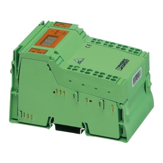
UM EN FLX ASI SYS PRO INST AS-Interface Gateway for PROFIBUS with standard function FLX ASI MA PB SF 2.2.1 Description The AS-i master (gateway) establishes the connection between PROFIBUS DP and the AS- Interface system. From the point of view of the application program, the AS-i master is a slave, for the AS-Interface system it represents the master. -
Page 31: Housing Dimensions
If no PC is available, startup, troubleshooting, and configuration on the AS-i system canalso be carried out directly on the device using the two buttons, the three-digit display, and the LEDs. This also includes the addressing of the connected slaves in your AS-i network. 2-11 7513_en_01 PHOENIX CONTACT... -
Page 32: Mounting/Demounting The Master Flx Asi Ma Pb Sf
UM EN FLX ASI SYS PRO INST 2.2.4 Mounting/demounting the Master FLX ASI MA PB SF Mounting/demounting the device on a DIN rail Mode 7793a001c 7793a001b 7793a001a Figure 2-14 Mounting/demounting the device on a DIN rail • Assembly: Use a screwdriver to reach into the latch and pull the latch downwards (A). -
Page 33: Power Supply And As-I Connection Method
Use a power supply unit that also supplies the AS-i master with voltage and, like all other AS-i components, can be connected to the AS-i cable at any point, see also "Power Supply Units" on page 3-1. 2-13 7513_en_01 PHOENIX CONTACT... -
Page 34: Diagnostic And Status Indicators
UM EN FLX ASI SYS PRO INST 2.2.7 Diagnostic and Status Indicators 7793A005 Figure 2-17 Diagnostic and Status Indicators Designation Colour Meaning power green Electronics module operating voltage Module/network status PROFIBUS green/red AS-i configuration error config error AS-i operating voltage... -
Page 35: As-Interface Gateway For Profibus With Extended Function Flx Asi Ma 2 Pb Ef
Three-digit LCD for displaying the respective operating state of the device and the configuration menu Four buttons for hand operations Ground AS-i power supply, circuit 2 AS-i circle 2 AS-i power supply, circuit 1 AS-i circle 1 7810a000 Figure 2-18 AS-i master FLX ASI MA 2 PB EF 2-15 7513_en_01 PHOENIX CONTACT... -
Page 36: Housing Dimensions
UM EN FLX ASI SYS PRO INST Features – Double master – Diagnostic and status indicators – Three-digit LCD – AS-i connection via spring-cage terminal block – Up to 62 AS-i slaves with a maximum of 248 inputs and 248 outputs –... - Page 37 (GSD) to start up AS-i masters. It can be downloaded free of charge at www.phoenixcontact.net/download. By default, the device is set to PROFIBUS address 3. The PROFIBUS address can be modified with two buttons, the three-digit display and the LEDs directly at the device. 2-17 7513_en_01 PHOENIX CONTACT...
-
Page 38: Mounting/Demounting The Master Flx Asi Ma 2 Pb Ef
UM EN FLX ASI SYS PRO INST Configuration You may also start up, troubleshoot, and configure the AS-i systems with the help of the buttons or the multi-line LCD directly on the device. All functions required can be conveniently carried out in the advanced display mode. -
Page 39: Connecting The Master Flx Asi Ma 2 Pb Ef
Connect the AS-i cables (3, 5) to the corresponding terminals. • Connect the AS-i power supply (2, 4). CAUTION: Observe the required polarity. • Connect the PROFIBUS to the 9-pin D-SUB female connector (see "Connection to PROFIBUS DP" on page 2-20). 2-19 7513_en_01 PHOENIX CONTACT... -
Page 40: Power Supply And As-I Connection Method
UM EN FLX ASI SYS PRO INST Connection to PROFIBUS DP 7 5 1 3 A 0 1 8 Figure 2-22 Connection to PROFIBUS DP Assignment RxD/TxD-P, cable B GND, reference potential up to +5 V +5 V RxD/TxD-N, cable A 2.3.6... -
Page 41: Diagnostic And Status Indicators
Change editing Change mode, Change to next higher menu, Confirm selection Further technical information can be found in the data sheet and in the user manual: AS-i-Gateways for PROFIBUS, UM EN FLX ASI MA PB SF/EF. 2-21 7513_en_01 PHOENIX CONTACT... - Page 42 UM EN FLX ASI SYS PRO INST 2-22 PHOENIX CONTACT 7513_en_01...
-
Page 43: Power Supply Units
45 Hz - 65 Hz frequency DC input: 90 - 250 V DC input voltage DC output: 30 V DC output voltage Reset button Floating EFD output EFD internal/external switch Green DC OK indicator UTA 107 universal DIN rail adapter 7513_en_01 PHOENIX CONTACT... -
Page 44: Product Versions For The As-Interface System
All AS-i power supply units from Phoenix Contact are fitted with an active PFC filter (Power Factor Correction). In addition to the filter function, this circuit ensures mains buffering of more than 40 ms across the entire input voltage range. -
Page 45: Housing Dimensions Of The Power Supply Units
Housing Dimensions of the Power Supply Units 7513A019 Figure 3-2 Housing dimensions of the ASI QUINT 100-240/2.4 A EFD power supply unit in mm 7513A020 Figure 3-3 Housing dimensions of the ASI QUINT 100-240/4.8 A EFD power supply unit in mm 7513_en_01 PHOENIX CONTACT... -
Page 46: Mounting/Removing Power Supply Units
UM EN FLX ASI SYS PRO INST Mounting/Removing Power Supply Units CAUTION: Never carry out work when voltage is present. CAUTION: Explosion hazard Never carry out work when voltage is present. CAUTION: In order to ensure sufficient convection, a minimum spacing of 5 cm must be maintained between other modules above and below the device. -
Page 47: Mounting On The Din Rail (Flat Mounting Position)
In order to comply with UL approval, use copper cables that are designed for operating temperatures > 75°C. For reliable and safe-to-touch connections, strip the cable ends according to Figure 3-6. Figure 3-6 Stripping length NOTE: Each AS-Interface system may only be supplied by one AS-Interface power supply unit. 7513_en_01 PHOENIX CONTACT... - Page 48 UM EN FLX ASI SYS PRO INST PHOENIX CONTACT 7513_en_01...
-
Page 49: Slaves
Connections The bus and supply are connected to the AS-i flat-ribbon cable using the penetration technique. The I/O devices are connected via M12 connectors using SPEEDCON fast connection technology. Degree of protection The devices have IP65/67 protection. 7513_en_01 PHOENIX CONTACT... -
Page 50: Housing Versions For Fieldline Extension As-I M12 Devices
UM EN FLX ASI SYS PRO INST 4.1.1 Housing Versions for Fieldline Extension AS-i M12 Devices Two housing versions are available for Fieldline Extension AS-i M12 devices. r - N o . : r - N D I O o . :... -
Page 51: Housing Dimensions Of Fieldline Extension As-I M12 Devices
4.1.2 Housing Dimensions of Fieldline Extension AS-i M12 Devices 7465c002 Figure 4-2 Housing dimensions of Fieldline Extension AS-i M12 devices (DI/DO/DIO) in mm 7509b003 Figure 4-3 Housing dimensions of Fieldline Extension AS-i M12 devices (DIO) in mm 7513_en_01 PHOENIX CONTACT... -
Page 52: Basic Structure Of Fieldline Extension As-I M12 Devices
UM EN FLX ASI SYS PRO INST 4.1.3 Basic Structure of Fieldline Extension AS-i M12 Devices Figure 4-4 shows the basic structure of the devices. Depending on the device function, the device may not have all of the elements shown. These elements are marked with an asterisk. -
Page 53: Mounting Fieldline Extension As-I M12 Devices
Tighten the mounting screws on the support plate with a maximum of 0.8 Nm. Use the protection against unlocking (FLX ASI M12 FS, Order No. 2773539) to prevent the device from getting unlocked unintentionally. Screw the protection against unlocking to one of the mounting holes (1) in Figure 4-5. 7513_en_01 PHOENIX CONTACT... - Page 54 UM EN FLX ASI SYS PRO INST DIN rail mounting Mounting • Place the device with the bottom metal edge (1) on the DIN rail. • Push the device forwards (A) until it snaps onto the DIN rail. 7513A036 Figure 4-6...
-
Page 55: Flat-Ribbon Cable
Other cable materials are also available, which have a high level of resistance to chemicals and can permanently withstand UV light. However, the selected material does affect the mechanical properties of the outer cable sheath. 7513_en_01 PHOENIX CONTACT... -
Page 56: Penetration Technique
UM EN FLX ASI SYS PRO INST 4.1.6 Penetration Technique For the AS-i flat-ribbon cable, the penetration technique is used as the connection method. The penetration technique enables contact to be established quickly, easily, and reliably between the cable and the device without having to strip or cut the cable in any way. No special tools are required. -
Page 57: Connecting As-Interface And The Auxiliary Voltage Aux To M12 Devices
(D). Then close the locking latch (E). The device is connected to the AS-i cable(s) using the penetration technique by snapping in the locking latch. 7472B004 Figure 4-10 Inserting the AS-i flat-ribbon cable 7513_en_01 PHOENIX CONTACT... -
Page 58: Pin Assignment Of The Inputs And Outputs
UM EN FLX ASI SYS PRO INST To reverse the orientation of the cables, proceed as follows: • Remove the cable routing aid from the device using a screwdriver (A) and turn it over (B). • Insert the cabling routing aid in the device again (C). Insert the corresponding flat-ribbon cable in the cable routing aid (D). -
Page 59: Labeling Fieldline Extension As-I M12 Devices
(3 in Figure 4-13) (108X16) WH 7513B029 Figure 4-13 Labeling options All of the above labeling options are self-adhesive and supplied on DIN A4 sheets. For professional labeling, Phoenix Contact offers the CMS-MARK-WIN software (see Phoenix Contact CLIPLINE catalog). 4-11 7513_en_01 PHOENIX CONTACT... -
Page 60: Diagnostic And Status Indicators Of Fieldline Extension As-I M12 Devices
UM EN FLX ASI SYS PRO INST 4.1.10 Diagnostic and Status Indicators of Fieldline Extension AS-i M12 Devices Diagnostic indicators Diagnostic indicators (green/yellow/red) indicate whether an error is present. In the event of an error, they indicate the error type and location. A Fieldline Extension AS-i M12 device is operating correctly if all of the green diagnostic indicators are on. -
Page 61: Setting The Address For Fieldline Extension As-I M12 Devices
Push the protective cap back onto the female addressing connector. 7472B006 Figure 4-15 Female addressing connector For additional information about addressing, please refer to the user manual: AS-Interface Addressing Device, ASI CC ADR UM E, Order No. 9013727 4-13 7513_en_01 PHOENIX CONTACT... -
Page 62: Replacing The Electronics Module
UM EN FLX ASI SYS PRO INST 4.1.12 Replacing the Electronics Module If in the event of servicing it is necessary to replace the electronics module, proceed as follows: • Release the locking latch (A). • Remove the electronics module from the mounting base (B). -
Page 63: Description For Fieldline Extension As-I M8 Devices
The bus and supply (20 V DC PELV to 30 V DC PELV) are connected via an M12 screw connector using SPEEDCON fast connection technology. The I/O devices are connected via M8 connectors. Degree of protection The devices have IP65/67 protection. 4-15 7513_en_01 PHOENIX CONTACT... -
Page 64: Housing Versions For Fieldline Extension As-I M8 Devices
UM EN FLX ASI SYS PRO INST 4.2.1 Housing Versions for Fieldline Extension AS-i M8 Devices Independent of the bus system, two housing versions are available for Fieldline Extension AS-i M8 devices. 7513A001 Figure 4-17 Housing versions for Fieldline Extension AS-i M8 devices... -
Page 65: Housing Dimensions Of Fieldline Extension As-I M8 Devices
AS-i M8 Devices 26,5 29,8 7513A002 Figure 4-18 Housing dimensions of Fieldline Extension AS-i M8 devices in mm (digital input devices) 7513A003 Figure 4-19 Housing dimensions of Fieldline Extension AS-i M8 devices in mm (digital I/O devices) 4-17 7513_en_01 PHOENIX CONTACT... -
Page 66: Basic Structure Of Fieldline Extension As-I M8 Devices
UM EN FLX ASI SYS PRO INST 4.2.3 Basic Structure of Fieldline Extension AS-i M8 Devices Figure 4-20 shows the basic structure of Fieldline Extension AS-i M8 devices. 7513A004 Figure 4-20 Basic structure of Fieldline Extension AS-i M8 devices Top and bottom fixing clip... -
Page 67: Mounting Fieldline Extension As-I M8 Devices
4 mm (M4) and a maximum head diameter of 7 mm and two retaining washers. The screws should have a minimum length of 30 mm. DIO 4/4 7513A009 Figure 4-21 Front mounting of a Fieldline Extension AS-i M8 device Tighten the mounting screws with a maximum of 0.8 Nm. 4-19 7513_en_01 PHOENIX CONTACT... -
Page 68: Connecting As-Interface And The Auxiliary Voltage Aux To M8 Devices
UM EN FLX ASI SYS PRO INST 4.2.5 Connecting AS-Interface and the Auxiliary Voltage AUX to M8 Devices For Fieldline Extension AS-i M8 devices, the AS-i bus and the power supply are connected via an M12 female connector. Fieldline Extension AS-i output devices also require the auxiliary voltage AUX, which is likewise connected via this M12 female connector. -
Page 69: Pin Assignment Of The Inputs And Outputs
Complete a labeling field and snap it into the relevant slot. • If you want to replace a labeling field, it can be removed using a small screwdriver. For professional labeling, Phoenix Contact offers the CMS-MARK-WIN software (see Phoenix Contact CLIPLINE catalog). 4-21... -
Page 70: Diagnostic And Status Indicators Of Fieldline Extension As-I M8 Devices
UM EN FLX ASI SYS PRO INST 4.2.9 Diagnostic and Status Indicators of Fieldline Extension AS-i M8 Devices Diagnostic indicators Diagnostic indicators (green/red) indicate whether or not an error is present. In the event of an error, they indicate the error type and location. A Fieldline Extension AS-i M8 device is operating correctly if all of the green indicators are on. -
Page 71: Setting The Address For Fieldline Extension As-I M8 Devices
Connect the AS-i round cable to the AS-i connection on the device. 7513A030 Figure 4-25 Addressing and AS-i connection For additional information about addressing, please refer to the user manual: AS-Interface Addressing Device, ASI CC ADR UM E, Order No. 9013727 4-23 7513_en_01 PHOENIX CONTACT... -
Page 72: Description For As-I Control Cabinet Modules
The bus, I/O devices, and supply are connected via plug-in COMBICON connections. Degree of protection The modules have IP20 protection. 4.3.1 Product Versions for AS-i Control Cabinet Modules The following control cabinet modules are available from Phoenix Contact for the AS-i system: Description Order Designation Order No. -
Page 73: Description For Asi Io Me Di 4 Ab
AB slave with extended addressing options for up to 62 AS-i slaves – Plug-in COMBICON connections – Communication monitoring – Inputs for 2 and 3-wire sensors – Inputs supplied from either the AS-i supply or the external auxiliary voltage – IP20 protection 4-25 7513_en_01 PHOENIX CONTACT... -
Page 74: Description For Asi Io Me Dio 4/3 Ab
UM EN FLX ASI SYS PRO INST 4.3.3 Description for ASI IO ME DIO 4/3 AB The ASI IO ME DIO 4/3 AB is an AS-Interface I/O module with four digital inputs and three digital outputs (AB slave). It is used to input and output digital signals in the control cabinet. -
Page 75: Description For Asi Io Me Dio 4/4 Ab
Plug-in COMBICON connections – Communication monitoring – Inputs for 2 and 3-wire sensors – Inputs supplied from either the AS-i supply or the external auxiliary voltage – Outputs supplied from the external auxiliary voltage – IP20 protection 4-27 7513_en_01 PHOENIX CONTACT... -
Page 76: Housing Dimensions Of Control Cabinet Modules
UM EN FLX ASI SYS PRO INST 4.3.5 Housing Dimensions of Control Cabinet Modules 1 0 5 2 2 , 5 7 5 1 3 A 0 2 1 Figure 4-29 Housing dimensions of modules in mm 4.3.6 Mounting Control Cabinet Modules Snap the module directly onto a DIN rail (1). -
Page 77: Terminal Assignment Of Control Cabinet Modules
O1, O–1, O2, O–2 O1, O–1, O2, O–2 O1, O–1, O2, O–2 O1, O–1, O2, O–2 O3, O–3 O3, O–3 O3, O–3, O4, O–4 O3, O–3, O4, O–4 AS-i+, AS-i– AS-i+, AS-i– AS-i+, AS-i– AS-i+, AS-i– AUX+, AUX– AUX+, AUX– AUX+, AUX– AUX+, AUX– 4-29 7513_en_01 PHOENIX CONTACT... -
Page 78: Diagnostic And Status Indicators Of Control Cabinet Modules
UM EN FLX ASI SYS PRO INST 4.3.9 Diagnostic and Status Indicators of Control Cabinet Modules A S I I O M E D I 4 A B A S I I O M E D I O 4 / 4 A B... -
Page 79: Setting The Address For Control Cabinet Modules
F A U L T I N T P W R A D D R 7 5 1 3 A 0 2 3 Figure 4-34 Connecting the addressing device using the example of an ASI IO ME DI 4 AB 4-31 7513_en_01 PHOENIX CONTACT... -
Page 80: Setting The Sensor Power Supply
UM EN FLX ASI SYS PRO INST 4.3.11 Setting the Sensor Power Supply You can specify whether the sensor is to be supplied from the AS-i circuit or from an external power supply. For the ASI IO ME DI 4 AB and ASI IO ME DIO 4/3 modules, proceed as follows: •... - Page 81 CAUTION: Use a PELV power supply The auxiliary voltages for the input/output supply must be taken from an isolated power supply (PELV according to IEC 60364-4-41). For additional information about the control cabinet modules, please refer to the corresponding data sheets. 4-33 7513_en_01 PHOENIX CONTACT...
- Page 82 UM EN FLX ASI SYS PRO INST 4-34 PHOENIX CONTACT 7513_en_01...
-
Page 83: Configuration
100 mA to 200 mA and a slave requires 30 mA to 60 mA. In addition, the sensors and actuators that are supplied directly via AS-i must be taken into consideration. 7513_en_01 PHOENIX CONTACT... -
Page 84: Selecting The Cable
UM EN FLX ASI SYS PRO INST Please note that the sensors connected to the AS-i devices are supplied via the power supply unit. The connected actuators are operated separately via the black AS-i cable. Example Calculation: AS-i system with 25 slaves and 100 sensors. -
Page 85: Integrating The As-I System In The Control System
Inline can be used in combination with a corresponding Inline bus coupler. Together with a modular ILC1xx or ILC3xx compact controller from Phoenix Contact, the ASI MA IL UNI AS-i gateway for Inline. becomes a compact control unit including master with Ethernet interface. - Page 86 UM EN FLX ASI SYS PRO INST PHOENIX CONTACT 7513_en_01...
-
Page 87: General Information About Installation
Cables must not enter the shear area of moving machine parts. – Do not install bus cables at right angles to driving paths and machine movements. – Use cable ducts or cable jumpers. Observe the specifications for the cable used. 7513_en_01 PHOENIX CONTACT... -
Page 88: Interference Suppression Measures
Interference Suppression Measures Phoenix Contact recommends connecting relay coils or motor coils with an RC element to protect the devices against interference. Depending on the application, the delay time of the relay can be increased by approximately 1 ms. -
Page 89: Installation Instructions
U Mounting Distances No specific distances must be observed between devices or between a device and a cabinet door or cover. Mounting distances are determined solely by the connectors used and the bending radii of the cables. 7513_en_01 PHOENIX CONTACT... - Page 90 UM EN FLX ASI SYS PRO INST PHOENIX CONTACT 7513_en_01...
-
Page 91: Startup
For additional information about addressing, please refer to the user manual: AS-Interface Addressing Device, ASI CC ADR UM E, Order No. 9013727 7513_en_01 PHOENIX CONTACT... -
Page 92: Configuring The Master
UM EN FLX ASI SYS PRO INST Configuring the Master To operate and monitor the AS-i system, the AS-i master constantly compares the actual status of all slaves with the desired status. Therefore the AS-i master must be informed once of the desired status of the system during AS-i system startup;...
Need help?
Do you have a question about the UM EN FLX ASI SYS PRO INST and is the answer not in the manual?
Questions and answers