
Related Manuals for Phoenix Contact IL PB BK DI8 DO4/EF-PAC


Summary of Contents for Phoenix Contact IL PB BK DI8 DO4/EF-PAC
- Page 1 AUTOMATION User manual UM EN IL PB BK DI8 DO4/EF-PAC Order No. – Diagnostic and firmware functions of the IL PB BK DI8 DO4/EF-PAC bus coupler...
- Page 3 AUTOMATION User manual Diagnostic and firmware functions of the IL PB BK DI8 DO4/EF-PAC bus coupler 12/2009 Designation: UM EN IL PB BK DI8 DO4/EF-PAC Revision: Order No.: – This user manual is valid for: Designation Order No. IL PB BK DI8 DO4/EF-PAC...
- Page 4 User group of this manual The use of products described in this manual is oriented exclusively to Phoenix Contact accepts no liability for erroneous handling or damage to products from Phoenix Contact or third-party products resulting from disregard of information contained in this manual.
- Page 5 The receipt of technical documentation (in particular data sheets, installation instructions, manuals, etc.) does not constitute any further duty on the part of Phoenix Contact to furnish information on alterations to products and/or technical documentation. Any other agreement shall only apply if expressly confirmed in writing by Phoenix Contact.
- Page 6 Phoenix Contact. Violators are liable for damages. Phoenix Contact reserves all rights in the case of patent award or listing of a registered design. Third-party products are always named without reference to patent rights. The existence of such rights shall not be excluded.
-
Page 7: Table Of Contents
PROFIsafe application notes ....................5-1 IO-Link ............................6-1 IO-Link call ......................6-1 Appendix ..........................A-1 Error codes for PCP communication..............A-1 Error codes for DP/V1 and VC1 communication..........A-3 Error codes for F-Parameters ................A-4 Format of the parameter telegram ..............A-5 7725_en_01 PHOENIX CONTACT... - Page 8 IL PB BK DI8 DO4/EF-PAC Object dictionaries ........................B-1 Slot 0 ......................... B-1 Slot 1 ......................... B-8 Slots 2 to 63....................... B-8 PHOENIX CONTACT 7725_en_01...
-
Page 9: The Profibus Bus Coupler
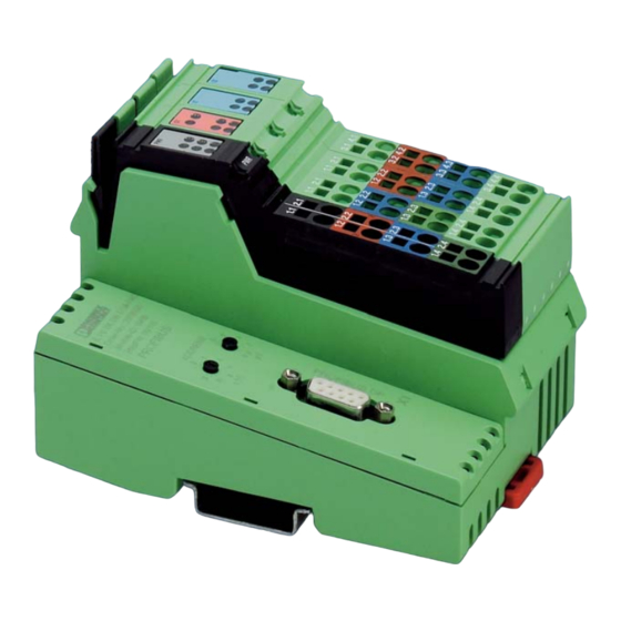
The PROFIBUS bus coupler can be ordered using Order No. 2692322. Connectors, labeling fields, and an end plate are supplied as standard. P W R 7725A001 Figure 1-1 The IL PB BK DI8 DO4/EF-PAC PROFIBUS bus coupler Scope of supply – PROFIBUS bus coupler (1) –... - Page 10 (see "PROFIsafe application notes" on page 5-1). For additional information about the bus coupler, please refer to the following documents: Data sheet: DB EN IL PB BK DI8 DO4/EF-PAC User manual: IL SYS INST UM E, Order No. 2698737 They can be downloaded at: www.phoenixcontact.net/catalog...
-
Page 11: Diagnostics
"IL PB BK DI8 DO4 Format", "Status-PDU Diagnostics" or "ID-Specific Diagnostics". By default, "IL PB BK DI8 DO4 Format" is activated. The"Status-PDU Diagnostics" format must be set for diagnostics of PROFIsafe I/O modules. Figure 2-1 Diagnostic formats dialog box 7725_en_01 PHOENIX CONTACT... -
Page 12: Diagnostics In The Il Pb Bk Di8 Do4 Format
IL PB BK DI8 DO4/EF-PAC 2.1.1 Diagnostics in the IL PB BK DI8 DO4 format This diagnostic format consists of the following blocks: PROFIBUS standard diagnostics ID-specific diagnostics Status diagnostics (terminal status) Channel-specific diagnostics Revision diagnostics (manufacturer-specific) Status-PDU (manufacturer-specific) From block 2 onwards the diagnostic telegram is dynamic. The individual number of bytes in a block depends on the station structure. - Page 13 Channel-specific diagnostics (header) slot 2 Channel IN/OUT and channel number slot 2 Channel and error type slot 1 Slot number Channel-specific diagnostics (header) slot 10 Channel IN/OUT and channel number slot 10 Channel and error type slot 10 7725_en_01 PHOENIX CONTACT...
- Page 14 IL PB BK DI8 DO4/EF-PAC Table 2-1 IL PB BK DI8 DO4-PAC format diagnostics Byte Bit 7 Bit 6 Bit 5 Bit 4 Bit 3 Bit 2 Bit 1 Bit 0 Meaning Block 5 Version (start with C1) Block 6...
- Page 15 Slave has more diagnostic information than displayed in the telegram Table 2-5 Byte: Master address 0-125 (00 Master address following parameterization, default address is 255 (FF Table 2-6 Byte 5 and 6: ID number 0-225 (00 ID number high byte 0-225 (00 ID number low byte 7725_en_01 PHOENIX CONTACT...
- Page 16 IL PB BK DI8 DO4/EF-PAC Block 2: ID-specific diagnostics The table shows the faulty local bus devices. For every faulty terminal, a "1" is entered. In the first byte of the block, bits 0 to 5 specify the number of local bus devices and therefore the length L of the block (8 devices for each byte, maximum).
- Page 17 ET: 6 = Cable break ET: 7 = Upper limit value exceeded ET: 8 = Lower limit value exceeded ET: 9 = General error Block 5: Revision diagnostics Indicates the firmware version, e.g., C3 = Version 3 7725_en_01 PHOENIX CONTACT...
-
Page 18: Status Pdu Diagnostic Format
IL PB BK DI8 DO4/EF-PAC Block 6: Status PDU The sixth block is also encoded as a status PDU block, but in manufacturer-specific format. The information stored here does not usually need to be evaluated. Byte 5 indicates the baud rate at which the local bus is operated. -
Page 19: Id-Specific Diagnostic Format
Terminals 25 to 32 (values 0 to 255) Terminals 33 to 40 (values 0 to 255) Terminals 41 to 48 (values 0 to 255) Terminals 49 to 56 (values 0 to 255) Terminals 57 to 63 (values 0 to 127) 7725_en_01 PHOENIX CONTACT... -
Page 20: Representing The Error Codes
IL PB BK DI8 DO4/EF-PAC Representing the error codes 2.2.1 Local diagnostic indicators Error type and error no. are indicated by flashing codes of the local diagnostic LEDs (LED FS and LED FN). P W R 7725A002 Figure 2-2 Local diagnostic indicators on the bus coupler... -
Page 21: Error Type And Error No
PROFIsafe Activate Status-PDU diagnostics when parameter error parameterizing the bus coupler in your controller and determine the exact error location and error cause. 2-11 7725_en_01 PHOENIX CONTACT... - Page 22 PROFIBUS address of the Check the PROFIBUS address of the IL PB BK DI8 DO4/EF-PAC is IL PB BK DI8 DO4/EF-PAC. After the address is set, larger than 126. the IL PB BK DI8 DO4/EF-PAC must be restarted. More than 244 bytes are required Reduce the number of terminals in the station or group for the configuration.
- Page 23 Check the amount of process data and reduce the local bus is greater than 244 number of devices in the station. bytes. Local bus error within the station Local bus was stopped. Check the configuration of the station. 2-13 7725_en_01 PHOENIX CONTACT...
- Page 24 IL PB BK DI8 DO4/EF-PAC 2-14 PHOENIX CONTACT 7725_en_01...
-
Page 25: Acyclic Communication (Dp/V1 And Pcp)
Access to the operator interface is usually acyclic. Up to 16 terminals capable of PCP can be connected to the IL PB BK DI8 DO4/EF-PAC bus coupler. 7725_en_01... -
Page 26: Pcp Communication Basics
IL PB BK DI8 DO4/EF-PAC PCP communication basics PCP (Peripherals Communication Protocol) controls the transmission of parameter data in the local bus. Special PCP services are available for this purpose. Application example To explain the basics of PCP communication, the following concrete PCP application is... - Page 27 Program invocation – Program invocation type objects, i.e., program sequences that can be run. For additional information about PCP communication, please refer to the IBS SYS PCP G4 UM E user manual, Order No. 2745169. 7725_en_01 PHOENIX CONTACT...
-
Page 28: Acyclic Communication In Dp/V1 Mode
– 2 to 63 When accessing the IL PB BK DI8 DO4/EF-PAC bus coupler, use the DP/V1 format. Read and write accesses can be executed in one step (request -> response). The PCP data from I/O terminals is addressed via 16-bit object indices. DP/V1 only has fields for 8-bit indices. - Page 29 Structure of the data depending on the service Access Service Data Write objects DP/V1 write request Object data (IL PB BK DI8 DO4/EF-PAC) DP/V1 write response None Read objects DP/V1 read request None (IL PB BK DI8 DO4/EF-PAC) DP/V1 read response...
- Page 30 IL PB BK DI8 DO4/EF-PAC – <Slot>: The slot of the device to be addressed in the station. The bus coupler is addressed with slot = 0, the integrated DI8/DO4 terminals are addressed with slot = 1. Starting with the first connected device, the devices are addressed with slots 2 to 63.
- Page 31 The section below provides a few examples to aid understanding (all values in hex). These examples indicate how objects on the bus coupler and the I/O devices can be read and written. The station structure is as follows: – IL PB BK DI8 DO4/EF-PAC – IB IL 24 DI8-PAC – IB IL AI4/EF-PAC –...
- Page 32 IL PB BK DI8 DO4/EF-PAC Example 1: Reading the connected local PCP devices and their status (slot 0, index 5 on the bus coupler) Read request (master -> slave) Data Data structure 5E 00 05 20 DP/V1 Read / Slot / Index / Maximum Length Read request (slave ->...
- Page 33 The settings for channels 1 and 3 are the same as well as for channels 2 and 4. Bytes 9 to 12 are reserved and are indicated as 0. The Invoke ID was mirrored and the status indicates that communication was error-free. 7725_en_01 PHOENIX CONTACT...
- Page 34 IL PB BK DI8 DO4/EF-PAC Example 4: Writing the Config Table for channel 3 on the connected IB IL AI4/EF (slot 3, index 0080, subindex 3) Write request (master -> slave) Data Data structure 5F 03 2F 08 07 00 00 80 03 02 03 01 DP/V1 write/Slot/Index/Length/Write PCP...
- Page 35 A-1, this means that this object does not exist. The last 2 bytes are also part of the PCP error data, however, they are not used in this example. If they do not equal zero, refer to the relevant I/O device data sheet for more detailed information. 3-11 7725_en_01 PHOENIX CONTACT...
- Page 36 IL PB BK DI8 DO4/EF-PAC Example 6: In the event of an error: Reading an object on a device without PCP (slot 2, index 0080) Write request (master -> slave) Data Data structure 5F 02 2F 05 06 00 00 80 00...
-
Page 37: Acyclic Communication In Dp/V0 Mode Via Process Data
The VC1 module (listed in the GSD as "PD PCP x words") may be configured at any position after the IL PB BK DI8 DO4/EF-PAC bus coupler. We recommend configuring the VC1 device in the last position. In this way the configured slot and the actual slot occupied by the I/O device will always be the same. - Page 38 IL PB BK DI8 DO4/EF-PAC Start fragment: Byte 1: Service Byte 2: Terminal number Byte 3: Invoke ID Byte 4: Index high Byte 5: Index low Byte 6: Subindex Byte 7: Length, if required Byte 8: Data block, if required...
- Page 39 Byte 1 - Service in end fragment: Byte 1 Request/ Reserved Response Bit 7: Request/Response 0 = Request 1 = Response Bits 6 to 5: Fragment type 10 = Last fragment (end fragment) Bits 4 to 0: Reserved 3-15 7725_en_01 PHOENIX CONTACT...
- Page 40 IL PB BK DI8 DO4/EF-PAC Abort/error fragment: Byte 1: Service Byte 2: Error code, if required Byte n: Error code, if required Table 3-9 Byte 1 - Service in abort/error fragment: Byte 1 Request/ Reserved Response Bit 7: Request/Response 0 = Request...
- Page 41 For VC1, the parameters have the following meaning: – <Terminal number>: The IL PB BK DI8 DO4/EF-PAC bus coupler is counted as device 0, the integrated DI8/DO4 terminals as 1, and the first connected device and onwards as terminal = 2 ... –...
-
Page 42: Examples For Vc1 Services
IL PB BK DI8 DO4/EF-PAC 3.5.2 Examples for VC1 services Example 1: Reading the connected local PCP devices and their status (slot 0, index 5 on the bus coupler) Read request (master -> slave) Data (8 words VC1) Data structure... - Page 43 00 00 00 00 00 00 00 00 00 00 00 00 Clear response The response indicates that the command has been received. Here, the status is positive (=0). The communication data can be reset to the initial state via "Clear". 3-19 7725_en_01 PHOENIX CONTACT...
- Page 44 IL PB BK DI8 DO4/EF-PAC Example 3: Reading the Config Table on the connected IB IL AI4/EF (slot 3, index 0080) Read request (master -> slave) - Start fragment Data (4 words VC1) Data structure 06 03 00 00 80 00 I 00 00...
- Page 45 Data structure 00 I 00 00 00 00 00 00 00 Clear request/7 bytes unused Clear response (slave -> master) Data (4 words VC1) Data structure 00 00 00 00 00 00 00 00 Clear response 3-21 7725_en_01 PHOENIX CONTACT...
- Page 46 IL PB BK DI8 DO4/EF-PAC Example 4: Writing the Config Table on the connected IB IL AI4/EF (slot 3, index 0080, subindex 0) Write request (master -> slave) - Start fragment Data (4 words VC1) Data structure 17 03 00 00 80 00 0C 03...
- Page 47 If they do not equal zero, refer to the relevant device data sheet for more detailed information. The communication data can be reset to the initial state via "Clear". 3-23 7725_en_01 PHOENIX CONTACT...
- Page 48 IL PB BK DI8 DO4/EF-PAC Example 6: In the event of an error: Reading an object on a device without PCP function (slot 2, index 0080) Read request (master -> slave) Data (4 words VC1) Data structure 06 02 00 00 80 00 I 00 00...
-
Page 49: Dynamic Configuration
® The configuration, e.g., in STEP 7 , is carried out in the same way as for other modular slaves. The configuration can be created from the hardware catalog using drag & drop, see Figure 4-1. 7725_en_01 PHOENIX CONTACT... - Page 50 IL PB BK DI8 DO4/EF-PAC Open the "Properties" dialog box by double-clicking on a terminal. Figure 4-2 DI8 properties dialog box The "Parameter Assignment" tab can be used to specify whether a device should be active or inactive, see Figure 4-3.
- Page 51 Depending on the terminal type, substitute values (DO and AO) to be output in the event of an error can also be set at this point, for example. Furthermore, inputs (AI) can be parameterized. This is also carried out via the dialog box shown in Figure 4-3. 7725_en_01 PHOENIX CONTACT...
-
Page 52: Principle Of Dynamic Configuration
IL PB BK DI8 DO4/EF-PAC Principle of dynamic configuration In dynamic configuration, a maximum configuration is specified during configuration. The addresses are thus reserved in the PLC. Any subgroup of this maximum configuration can be operated. This type of subgroup can be selected and activated during configuration and runtime. - Page 53 Length of 5 to 12 bytes, maximum Byte 1: Byte 2: Byte 3: Byte 4: Length of data n Byte 5: Byte 4+n: x Bit = 0: Terminal and slot inactive Bit = 1: Terminal and slot active 7725_en_01 PHOENIX CONTACT...
-
Page 54: Startup
IL PB BK DI8 DO4/EF-PAC Startup 4.3.1 Planning configuration Figure 4-4 shows an example of the maximum configuration, as provided. All terminals are activated by default. ® Figure 4-4 Configuration in the STEP 7 hardware configurator Access to indices 4 and 6 described in the introduction is either via PROFIBUS DP/V1 or via the process data interface. -
Page 55: Options For Specifying The Active Configuration
Which option will be used in the end depends on the support of DP/V1 in the master. If DP/V1 is not (or inadequately) supported by the master, DP/V0 should be used. For ® ® SIMATIC STEP 7 CPUs, functions are available that have been prepared by Phoenix Contact. 7725_en_01 PHOENIX CONTACT... -
Page 56: Specifying The Active Configuration Via Dp/V0
IL PB BK DI8 DO4/EF-PAC 4.3.3 Specifying the active configuration via DP/V0 For DP/V0, the activation status can be accessed via Index 6 or 7. The structure of the objects differs slightly, therefore typical access is illustrated for both objects. - Page 57 Write response (slave -> master) Data (8 words VC1) Data structure 14 I 00 00 00 00 00 00 00 00 00 00 00 Write response/15 bytes unused 00 00 00 00 7725_en_01 PHOENIX CONTACT...
- Page 58 IL PB BK DI8 DO4/EF-PAC Access via index 7 Please observe the structure of index 7 when accessing it: Byte 1 Byte 2 Byte 3 Byte 4 Length of data n Byte 5 Byte 4+n Bit = 0: Terminal and slot inactive Bit = 1: Terminal and slot active In this example there are 7 connected terminals.
-
Page 59: Specifying The Active Configuration Via Dp/V1
5F 00 06 08 F2 00 00 00 00 00 00 00 Write/Slot/Index/Total length of data/ Length/8 bytes of object data Write response (slave -> master) Data (8 words VC1) Data structure 5F 00 06 08 Write/Slot/Index/Length 4-11 7725_en_01 PHOENIX CONTACT... - Page 60 IL PB BK DI8 DO4/EF-PAC 4.3.5 Summary Depending on the task and requirements in the control system, the illustrated services (process data interface DP/V0 or DP/V1) can be used to specify the configuration actually used by the application. In this example, the IB IL 24 DI24 and IB IL 24 DO8 terminals are deactivated with the illustrated services and therefore must not be connected.
-
Page 61: Profisafe Application Notes
The modules map 4 words of process data to the local bus and obtain the F-Parameters and iParameters from the parameter telegram via a 63-byte parameter block. The settings are provided in the GSD file. Connected PROFIsafe modules need 30 seconds before they can communicate and be parameterized. 7725_en_01 PHOENIX CONTACT... - Page 62 IL PB BK DI8 DO4/EF-PAC PHOENIX CONTACT 7725_en_01...
-
Page 63: Io-Link
IOLD objects are accessed with the IO-Link call being a standardized read and write access. It uses the mechanisms of PROFIBUS I&M functions (via DP/V1). For further information on IO-Link call communication can be found in the AH FLS PB M12 IOL 4 M12 application note. 7725_en_01 PHOENIX CONTACT... - Page 64 IL PB BK DI8 DO4/EF-PAC PHOENIX CONTACT 7725_en_01...
-
Page 65: A Appendix
Meaning A service parameter was specified with an impermissible value. Cause E.g., an incorrect length specification or an impermissible subindex. Remedy Check the parameters in the object description and send the service again with the corrected values. 7725_en_01 PHOENIX CONTACT... - Page 66 IL PB BK DI8 DO4/EF-PAC Communication error messages Table A-4 (Object access unsupported) Meaning The service used cannot be applied to this object. Cause E.g., a program sequence can be started or stopped, but not read. Remedy Check the object description to determine which services are supported for this object.
-
Page 67: A 2 Error Codes For Dp/V1 And Vc1 Communication
Incorrect sequence of fragments Incorrect data length during access PCP PDU size of 64 bytes (58 bytes of user data) per communication exceeded (Internal) timeout while reading (Internal) error while sending a request (Internal) error while receiving a service 7725_en_01 PHOENIX CONTACT... -
Page 68: A 3 Error Codes For F-Parameters
IL PB BK DI8 DO4/EF-PAC Error codes for F-Parameters F-Parameters contain information to adapt the PROFIsafe layer to particular customer specifications. Parameterization is also checked on a separate path of the PROFIsafe layer. For Status-PDU diagnostics the following parameter errors can be distinguished in the "PROFIsafe F-Parameter error"... -
Page 69: A 4 Format Of The Parameter Telegram
1: Manually acknowledge peripheral faults Bit 0 0: Stop local bus in the event of terminal failure 1: Operate local bus with available terminals The data for the configuration and the failsafe value can be found in the terminal-specific data sheets. 7725_en_01 PHOENIX CONTACT... - Page 70 IL PB BK DI8 DO4/EF-PAC Table A-10 Parameters for the I/O devices byte 1 Byte Meaning Byte 1 Bit 7 to bit 6 00: Start block ID for device Bit 5 to bit 4 Configuration 00: No configuration (e.g., DO)
- Page 71 Bit 5 to bit 0 Length of the ID function block Byte x+2 Bit 7 to bit 0 Order No. (last - n sign), ASCII Byte x+2+n Bit 7 to bit 0 Order No. (last sign), ASCII 7725_en_01 PHOENIX CONTACT...
- Page 72 IL PB BK DI8 DO4/EF-PAC PHOENIX CONTACT 7725_en_01...
- Page 73 Set bit 2 if the diagnostics of all connected terminals are to be read in again. This is only useful if terminals are connected for which object 18 (diag state) is implemented. Usually this includes all devices that use PCP. Therefore check in the relevant data sheet whether the terminal supports PCP. 7725_en_01 PHOENIX CONTACT...
- Page 74 IL PB BK DI8 DO4/EF-PAC Bit 3 can be used in the context of dynamic configuration. If a new activation status is specified via object 6 or 7, it is mandatory. If the connection to the PROFIBUS master is then interrupted and if the original parameterization is transmitted by the master during restart, the activation status is maintained.
- Page 75 More bytes can also be transmitted, however only up to 8 bytes, as the station can only manage a maximum of 63 terminals. 7725_en_01 PHOENIX CONTACT...
- Page 76 IL PB BK DI8 DO4/EF-PAC In the case of read access, the amount of data is based on the number of configured and available devices. If, for example, k = 18 devices are configured, you will receive the response m = 3+1 bytes.
- Page 77 Read and write Length: 8 bytes Note: For write access, all counters (index 20 to 25) are set to 0 The objects on slot 0 can be read and written with a single access attempt via DP/V1. 7725_en_01 PHOENIX CONTACT...
- Page 78 IL PB BK DI8 DO4/EF-PAC Index 255: Identification & Maintenance functions Function: Read and write I & M functions Access: Read and write Length: 64 bytes Note: Only possible via DP/V1 For this object, each access attempt - read or write - should be implemented in two stages (in accordance with specification IEC 61158-6, Section 6.1).
- Page 79 Please note, that when writing to I & M functions I & M1 to I & M4, the nonvolatile memory of the device is accessed. The memory is designed for a maximum of 100,000 write access operations. 7725_en_01 PHOENIX CONTACT...
- Page 80 IL PB BK DI8 DO4/EF-PAC Slot 1 On slot 1, indices are implemented with regard to the integrated DI8: Index 13: PD IN Function: Input data of the integrated DI8 Access: Read Length: 1 byte Slots 2 to 63 On slots 2-63, indices are implemented with regard to the I/O terminals that can be...
Need help?
Do you have a question about the IL PB BK DI8 DO4/EF-PAC and is the answer not in the manual?
Questions and answers