Table of Contents
Advertisement
Quick Links
Advertisement
Table of Contents

Related Manuals for Phoenix Contact FL MGUARD 1000 Series


Summary of Contents for Phoenix Contact FL MGUARD 1000 Series
- Page 1 FL MGUARD 1000 Installation and startup User manual UM EN FL MGUARD 1000...
- Page 2 FL MGUARD 1000 – Installation and startup UM EN FL MGUARD 1000, Revision 06 2021-01-25 This user manual is valid for: Designation Version Order No. FL MGUARD 1102 1153079 PHOENIX CONTACT GmbH & Co. KG • Flachsmarktstraße 8 • 32825 Blomberg • Germany phoenixcontact.com...
-
Page 3: Table Of Contents
Commissioning the device with the configuration from SD card ......36 Using web-based management................37 Restarting the device (reboot) ................39 Using the RESTful Configuration API ..............40 Smart mode ..........................41 Available smart mode functions................41 3 / 52 PHOENIX CONTACT 108413_en_06... - Page 4 Using smart mode ....................43 Device replacement, device defect, and repair ................45 Secure deletion of sensitive data................. 45 Device replacement..................... 45 Device defect and repair..................45 Disposal ......................46 Technical data .........................47 FL MGUARD 1102 ....................47 4 / 52 PHOENIX CONTACT 108413_en_06...
-
Page 5: For Your Safety
Intended use – The devices of the FL MGUARD 1000 series are security routers for industrial use, with integrated stateful packet inspection firewall. They are suitable for distributed protec- tion of production cells or individual machines against manipulation. -
Page 6: Modifications To The Product
Incorrect operation or modifications to the device can endanger your safety or damage the device. Do not repair the device yourself. If the device is defective, please contact Phoenix Contact. Safety notes To ensure correct operation and the safety of the environment and of personnel, the device must be installed, operated, and maintained correctly. -
Page 7: Security
(ISMS) to manage all of the infrastructure-based, organizational, and personnel measures that are needed to ensure compliance with information security directives. Furthermore, Phoenix Contact recommends that at minimum the following measures are taken into consideration. More detailed information on the measures described is available on the following websites (last accessed on 2021-01-15;... - Page 8 FL MGUARD 1000 product family • Observe the Change Notes for the respective firmware version. • Pay attention to the security advisories published on Phoenix Contact‘s Product Secu- rity Incident Response Team (PSIRT) website regarding any published vulnerabilities. Use up-to-date security software •...
-
Page 9: Latest Safety Instructions For Your Product
Latest safety instructions for your product Product Security Incident Response Team (PSIRT) The Phoenix Contact PSIRT is the central team for Phoenix Contact as well as for its sub- sidiaries, authorized to respond to potential security vulnerabilities, incidents and other se- curity issues related to Phoenix Contact products, solutions as well as services. - Page 10 FL MGUARD 1000 product family 10 / 52 PHOENIX CONTACT 108413_en_06...
-
Page 11: Device Description
Incident Response Team). Detected or reported security gaps are immediately analyzed and, if necessary, closed (see PSIRT). Thanks to the integrated mGuard Security Technology, the devices provide decentralized protection of production cells or individual machines against manipulation. 11 / 52 PHOENIX CONTACT 108413_en_06... -
Page 12: Product Overview
Immediately upon delivery, refer to the delivery note to ensure that the delivery is com- plete. • Submit claims for any transport damage immediately, and inform Phoenix Contact or your supplier as well as the shipping company without delay. •... -
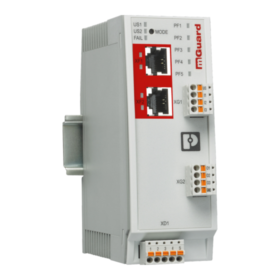
Page 13: Fl Mguard 1102
⑨ nector (Push-in contact) (See Section 3.5) (See Section 3.2) Network interface 2 / Net zone 2 (RJ45 Ethernet port) ⑤ (see Section 3.3) LNK/ACT LED (top) | SPD LED (bottom) (see Section 2.4.2) 13 / 52 PHOENIX CONTACT 108413_en_06... -
Page 14: Led Status And Diagnostic Indicators
The PF1 LED flashes with the power supply can the rhythm of a heartbeat. damage the device! Do not switch off the de- vice! Wait until the device has been started up com- pletely. 14 / 52 PHOENIX CONTACT 108413_en_06... - Page 15 “FAIL“ LED. ply can damage the four seconds. device! Do not switch off the device! Wait until the smart mode function has been completed suc- cessfully. 15 / 52 PHOENIX CONTACT 108413_en_06...
- Page 16 SPD (XF1-XF2) Green/or- On (or- 1000 Mbps (Gigabit Ethernet) ange ange) (Lower LED) On (green) 100 Mbps (Fast Ethernet) 10 Mbps (Ethernet) (if LNK/ACT LED active) No data transmission (When LNK/ACT LED is inactive) 16 / 52 PHOENIX CONTACT 108413_en_06...
- Page 17 Supply voltage not present or too low (see Section Green The devices do not have a redundant power supply. If the supply voltage at US1 is within the tolerance range, US2 LED also lights up. 17 / 52 PHOENIX CONTACT 108413_en_06...
- Page 18 A serious error occurred. ⇒ The device did not reach readi- (blinking) ness for operation. ⇒ All network interfaces have been deactivated. • Restart the device. • Contact your support, if necessary (see Section 1.9). 18 / 52 PHOENIX CONTACT 108413_en_06...
-
Page 19: Default Setting
During the initial device startup, immediately change the preset administrator password. Additionally, network access to the device is restricted by the firewall for incoming data traf- fic (see “Firewall (for incoming data traffic) = device access“). 19 / 52 PHOENIX CONTACT 108413_en_06... - Page 20 Sends NTP requests to available NTP servers via UDP port 123. Net zone 2 (XF2) Default setting: The following addresses (host names) of the NTP server have been preset: – 0.pool.ntp.org – 1.pool.ntp.org – 2.pool.ntp.org – 3.pool.ntp.org 20 / 52 PHOENIX CONTACT 108413_en_06...
- Page 21 NTP server Net zone 2 (XF2) Request via UDP port 123 Clients that are connected with the device via net zone 2 can synchronize their sys- tem time via the NTP server of the device. 21 / 52 PHOENIX CONTACT 108413_en_06...
- Page 22 All packets that are sent from net zone 2 (XF2), i.e. from subnetwork 192.168.1.0/24, to any target address are forwarded by the device (routed). (Rule: 192.168.1.0/24 --> 0.0.0.0/0 = ACCEPT). All other packets are rejected. 22 / 52 PHOENIX CONTACT 108413_en_06...
-
Page 23: Mounting And Installation
• Slightly swivel the bottom of the device away from the DIN rail (C). • Lift the device upwards away from the DIN rail (D). Figure 3-2 Removing the device 23 / 52 PHOENIX CONTACT 108413_en_06... -
Page 24: Connecting The Supply Voltage
Mount the module on a grounded DIN rail. • Functional grounding of the module is achieved when the module is snapped onto the grounded DIN rail or via clamping point 5 (functional ground – FE) of COMBICON connector XD1. 24 / 52 PHOENIX CONTACT 108413_en_06... -
Page 25: Connecting To The Network
Only use shielded twisted pair cables and corresponding shielded RJ45 connectors. In- sert the Ethernet cable with the RJ45 connector into a port of the twisted pair interface (network interface 1 or 2), until the connector engages with a click. 25 / 52 PHOENIX CONTACT 108413_en_06... -
Page 26: Connecting Switching Inputs And Switching Outputs (I/Os)
Remove COMBICON connector XG1 or XG2 from the device. • Connect the desired connecting cable to the COMBICON connector (see Table 3-3 and 3-4). • Plug COMBICON connector XG1 or XG2 onto the device. 26 / 52 PHOENIX CONTACT 108413_en_06... -
Page 27: Using An Sd Card
On principle, we cannot guarantee the functionality and compatibility of SD cards from other manufacturers. To avoid compatibility problems, we recommend using SD cards from Phoenix Contact. The SD card holder is located on the back of the device. Format: SD (32.0 mm × 24.0 mm × 2.1 mm) - Page 28 FL MGUARD 1000 product family 28 / 52 PHOENIX CONTACT 108413_en_06...
-
Page 29: Initial Startup
DHCP, DNS, NTP). Required components – Device with COMBICON connector (for XD1) – 24 V power supply – Network cable (Ethernet) – Wire bridge (only Easy Protect Mode) – Configuration computer (only Router mode) 29 / 52 PHOENIX CONTACT 108413_en_06... -
Page 30: Operating The Device In "Easy Protect Mode
In Easy Protect Mode, firmware updates can be performed via the Smart Mode function "Updating from SD card" (see Section 5.1.4). Phoenix Contact regularly provides firmware updates. Any firmware updates available can be found on the product page for the respective device (e.g. phoenixcon- tact.net/product/1153079). - Page 31 (To protect several devices, connect them to the device via an additional switch.) • Connect the surrounding network to net zone 1 (XF1) via a switch ⇒ All network packets XF1 --> XF2 are rejected. ⇒ All network packets XF2 --> XF1 are accepted and forwarded. 31 / 52 PHOENIX CONTACT 108413_en_06...
-
Page 32: Operating The Device In Router Mode
⇒ The FAIL LED briefly lights up in red. During the boot process, the PF1–5 LEDs light up orange. ⇒ ⇒ The device is ready for operation when the PF1 LED flashes green (heartbeat). 32 / 52 PHOENIX CONTACT 108413_en_06... - Page 33 Open the Windows start menu and type “cmd” to open a command line. tion • Enter the command “ipconfig” and press the Enter button. ⇒ IPv4 address, subnet mask and default gateway of the Ethernet adapter are dis- played. 33 / 52 PHOENIX CONTACT 108413_en_06...
- Page 34 To test whether a configuration computer can reach the device via the network, proceed as follows: • Open the Windows start menu and type “cmd” to open a command line. • Enter the command “ping 192.168.1.1” and press the Enter button. 34 / 52 PHOENIX CONTACT 108413_en_06...
- Page 35 Initial startup ⇒ From the answer to the ping request, you can tell whether the device reacts to re- quests from the configuration computer. 35 / 52 PHOENIX CONTACT 108413_en_06...
-
Page 36: Commissioning The Device With The Configuration From Sd Card
Insert the SD card with the saved configuration (mguard-cofig.tar.gz) into the SD card holder. • Start the device. ⇒ The configuration is automatically imported from the SD card to the device and ap- plied there. 36 / 52 PHOENIX CONTACT 108413_en_06... -
Page 37: Using Web-Based Management
Enter the IP address of the connected network interface of the device into the address line of the web browser (e.g. https://192.168.1.1). ⇒ Since Phoenix Contact supplied the device with a self-signed security certificate that is unfamiliar to your browser, a certificate warning appears. Figure 4-5 Certificate warning (Firefox) •... - Page 38 The functions that can be configured by means of the web-based management are de- scribed in the “FL MGUARD 1000 – Web-based management” (UM EN MGUARD NT) user manual. Available in the download area of the respective product page in the Phoenix Contact webshop, e.g. under phoenixcontact.net/product/1153079. 38 / 52...
-
Page 39: Restarting The Device (Reboot)
• Briefly interrupt the power supply of the device. The device restarts. ⇒ ⇒ The PF1–5 LEDs light up orange. ⇒ The device is ready for operation when the PF1 LED flashes green (heartbeat). 39 / 52 PHOENIX CONTACT 108413_en_06... -
Page 40: Using The Restful Configuration Api
How to use the Config API is described in the “FL MGUARD 1000 – RESTful Configura- tion API” (UM EN MGUARD NT CONFIG API) user manual. Available in the download area of the respective product page in the Phoenix Contact webshop, e.g. under phoenixcontact.net/product/1153079. -
Page 41: Smart Mode
192.168.1.1, net mask: 24 – The default access rule for the web server (HTTPS) is restored for net zone 2 (see Section 2.5). – The rest of the device configuration, passwords and certificates remain unaltered. 41 / 52 PHOENIX CONTACT 108413_en_06... - Page 42 Requirement – A (single) valid update file signed by Phoenix Contact has to be stored on the first par- tition of the SD card. (If there is a second update file on the SD card, the smart mode function will be aborted;...
-
Page 43: Using Smart Mode
NOTE: Do not interrupt the power supply to the device! An interruption in the power supply can cause a device defect. ⇒ If all PF LEDs light up in green, the function has been executed successfully. • Restart the device. 43 / 52 PHOENIX CONTACT 108413_en_06... - Page 44 “FAIL“ the power supply can three times every four sec- LED. damage the device! onds. Do not switch off the de- vice! Wait until the function has been executed success- fully. 44 / 52 PHOENIX CONTACT 108413_en_06...
-
Page 45: Device Replacement, Device Defect, And Repair
Device defect and repair Repairs may only be carried out by Phoenix Contact. • Send defective devices back to Phoenix Contact for repair or to receive a replacement device. • We strongly recommend using the original packaging to return the product. -
Page 46: Disposal
Dispose of the product separately from other waste, i.e., via an appropriate collection site. – Dispose of packaging materials that are no longer needed (cardboard packaging, paper, bubble wrap sheets, etc.) with household waste in accordance with the cur- rently applicable national regulations. 46 / 52 PHOENIX CONTACT 108413_en_06... -
Page 47: Technical Data
(use copper wires that are suitable for 90 °C or equiv- alent) Nominal value 24 V DC Permissible voltage range FL MGUARD 1102 18 V DC ... 36 V DC Permissible ripple (within the permitted voltage range) 3.6 V 47 / 52 PHOENIX CONTACT 108413_en_06... - Page 48 Test intensity 3, criterion B Indirect discharge: Test intensity 3, criterion B Immunity in accordance with EN 61000-4-3 (IEC 1000-4-3) Requirements in accordance with DIN EN 61000-6-2 (electromagnetic fields) Test intensity 3, criterion A 48 / 52 PHOENIX CONTACT 108413_en_06...
- Page 49 Immunity in accordance with EN 61000-4-5 (IEC 1000-4-5) (surge) Requirements in accordance with DIN EN 61000-6-2 Data cables: Test intensity 2, criterion B Power supply: Test intensity 1, criterion B Other Conformance CE conformity 49 / 52 PHOENIX CONTACT 108413_en_06...
- Page 50 FL MGUARD 1000 product family 50 / 52 PHOENIX CONTACT 108413_en_06...
- Page 51 The receipt of technical documentation (in particular user documentation) does not constitute any further duty on the part of Phoenix Contact to furnish information on modifications to products and/or technical documentation. You are responsible to verify the suitability and intended use of the products in your specific application, in particular with regard to observing the applicable standards and regulations.
- Page 52 Should you have any suggestions or recommendations for improvement of the contents and layout of our manuals, please send your comments to: tecdoc@phoenixcontact.com 52 / 52 PHOENIX CONTACT GmbH & Co. KG • Flachsmarktstraße 8 • 32825 Blomberg • Germany phoenixcontact.com...
- Page 54 PHOENIX CONTACT GmbH & Co. KG Flachsmarktstraße 8 32825 Blomberg, Germany Phone: +49 5235 3-00 Fax: +49 5235 3-41200 E-mail: info@phoenixcontact.com phoenixcontact.com...
Need help?
Do you have a question about the FL MGUARD 1000 Series and is the answer not in the manual?
Questions and answers