Table of Contents
Advertisement
Quick Links
Advertisement
Table of Contents

Related Manuals for Phoenix Contact IB IL 24 PSDO 8-PAC


Summary of Contents for Phoenix Contact IB IL 24 PSDO 8-PAC
- Page 1 IB IL 24 PSDO 8-PAC Inline module with safe digital outputs User manual...
- Page 2 UM EN IB IL 24 PSDO 8-PAC, revision 05 2017-11-08 This user manual is valid for: Designation Revision Order No. as of HF/FW/FW IB IL 24 PSDO 8-PAC 00/201/100 2985631 PHOENIX CONTACT GmbH & Co. KG • Flachsmarktstraße 8 • 32825 Blomberg • Germany phoenixcontact.com...
-
Page 3: Table Of Contents
Lokalbus (INTERBUS) ................. 31 2.10.2 Andere Bussysteme (PROFIBUS, PROFINET) ........31 Inline-Potenzial- und Datenrangierung sowie Inline-Stecker.............33 Inline-Potenzial- und Datenrangierung ..............33 Versorgungsspannung U ................... 33 Versorgungsspannung U .................. 34 Belegung der Klemmpunkte ................36 3 / 112 7619_en_04 PHOENIX CONTACT... - Page 4 IB IL 24 PSDO 8-PAC Montage, Demontage und elektrische Installation ..............39 Montage und Demontage ..................39 4.1.1 Auspacken des Moduls ................ 39 4.1.2 Allgemeines ..................39 4.1.3 DIP-Schalter einstellen ................ 40 4.1.4 Sicherheitsmodul montieren und demontieren ........43 Elektrische Installation ..................45 4.2.1...
- Page 5 Systemdaten ....................... 81 10.1.1 INTERBUS-Safety ................81 10.1.2 SafetyBridge ..................81 10.1.3 PROFIsafe ................... 81 10.2 IB IL 24 PSDO 8-PAC ..................82 10.3 Konformität zur EMV-Richtlinie................87 10.4 Bestelldaten ......................88 10.4.1 Bestelldaten: Sicherheitsmodul ............88 10.4.2 Bestelldaten: Zubehör ................88 10.4.3...
- Page 6 IB IL 24 PSDO 8-PAC Anhang: Stichwortverzeichnis....................105 Anhang: Änderungsnachweis ....................107 6 / 112 PHOENIX CONTACT 7619_en_04...
-
Page 7: Zu Ihrer Sicherheit
– Qualified application programmers and software engineers. The users must be familiar with the relevant safety concepts of automation technology as well as applicable stan- dards and other regulations. 7 / 112 7619_en_05 PHOENIX CONTACT... -
Page 8: Allgemeine Sicherheitshinweise
IB IL 24 PSDO 8-PAC General safety notes WARNING: Depending on the application, incorrect handling of the safety module can pose serious risks for the user When working with the safety module within the INTERBUS-Safety, SafetyBridge, or PROFIsafe system, please observe all safety notes included in this section. - Page 9 Repair work may not be carried out on the safety module. pairs In the event that an error cannot be removed, please contact Phoenix Contact immediately, engage a service engineer or send the faulty module directly to Phoenix Contact. Do not open the housing It is strictly prohibited to open the module housing.
-
Page 10: Elektrische Sicherheit
When selecting the equipment, please take into consideration the dirt and surge voltages which may occur during operation. The IB IL 24 PSDO 8-PAC module is designed for overvoltage category II (according to DIN EN 60664-1). If you expect surge voltages in the system, which exceed the values de- fined in overvoltage category II, take into consideration additional measures for voltage lim- itation. -
Page 11: Sicherheit Der Maschine Oder Anlage
The safety integrity level ascertained determines how to connect and parameterize the safety module within the overall safety function. Within an INTERBUS-Safety, SafetyBridge or PROFIsafe system, the IB IL 24 PSDO 8-PAC safety module can be used to achieve safety functions with the fol- lowing requirements: –... -
Page 12: Richtlinien Und Normen
Directives and standards The manufacturers and operators of machines and systems, in which the IB IL 24 PSDO 8-PAC module is used, are responsible for adhering to all applicable direc- tives and legislation. For the standards observed by the module, please refer to the certificate issued by the ap- proval body and the EC declaration of conformity. -
Page 13: Dokumentation
For the safe controller used – For PROFIsafe I/O modules – For PROFIsafe function blocks Please also observe the relevant information about PROFIBUS, PROFINET and PROFIs- afe, which is available on the Internet at profisafe.net. 13 / 112 7619_en_05 PHOENIX CONTACT... - Page 14 IB IL 24 PSDO 8-PAC Standard INTERBUS When working on the INTERBUS system and its components, you must always keep the listed user manuals and other items of product documentation to hand and observe the in- formation therein. IBS SYS INTRO G4 UM E...
-
Page 15: Verwendete Abkürzungen
For terms and abbreviations used for PROFIsafe, please refer to “Appendix: PROFIsafe terms used in the user manual” on page 91. 1.10 Safety hotline Should you have any technical questions, please contact our 24-hour hotline. Phone: +49 5281 9462777 E-mail: safety-service@phoenixcontact.com 15 / 112 7619_en_05 PHOENIX CONTACT... - Page 16 IB IL 24 PSDO 8-PAC 16 / 112 PHOENIX CONTACT 7619_en_05...
-
Page 17: Produktbeschreibung
The IB IL 24 PSDO 8-PAC module is an output module that is designed for use within an Inline station. The IB IL 24 PSDO 8-PAC safety module can be used as part of an Inline station at any point within an INTERBUS-Safety, SafetyBridge or PROFIsafe system. -
Page 18: Aufbau Des Sicherheitsmoduls
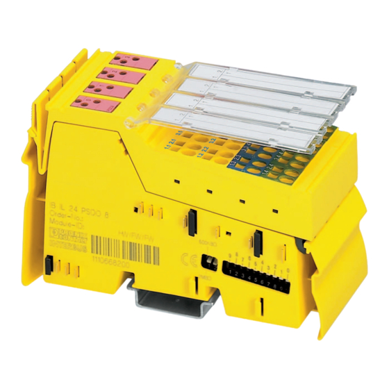
IB IL 24 PSDO 8-PAC Structure of the safety module 76192002 Figure 2-1 Structure of the safety module Data jumpers (local bus) Electronics base with labeling including version designation hardware/firmware/firm- ware (not shown) Switch for setting the transmission speed and the operating mode Switch for setting the protocol and address For more detailed information about setting the switches, please refer to Section “Setting... -
Page 19: Gehäusemaße
Product description Housing dimensions 71,5 48,8 76191008 Figure 2-2 Housing dimensions (in mm) 19 / 112 7619_en_05 PHOENIX CONTACT... -
Page 20: Sichere Digitale Ausgänge
IB IL 24 PSDO 8-PAC Safe digital outputs The safety module has safe positive switching digital outputs, which can be used as follows: – For two-channel assignment: – Four two-channel outputs – For single-channel assignment: – Eight single-channel outputs Technical data For the technical data for the safe outputs, please refer to Page 85. - Page 21 – Please observe the applicable C standards in your application (e.g., EN 1010), in which, for example, the number of controlled devices required to achieve a particular category is specified. 21 / 112 7619_en_05 PHOENIX CONTACT...
-
Page 22: Anschlussmöglichkeiten Für Aktoren In Abhängigkeit Von Der Parametrierung
IB IL 24 PSDO 8-PAC Connection options for actuators depending on the parameterization Actuators that meet various safety requirements depending on the parameterization can be connected to the outputs. For connection examples, please refer to Section 6, "Connection examples for safe outputs". -
Page 23: Lokale Diagnose- Und Status-Anzeigen
Product description Local diagnostic and status indicators PSDO8 76191003 Figure 2-3 Local diagnostic and status indicators on the IB IL 24 PSDO 8-PAC module Table 2-1 Local diagnostic and status indicators Green LED Diagnostics Off: Communications power not present Flashing at Communications power present, local bus not active 0.5 Hz:... - Page 24 IB IL 24 PSDO 8-PAC Table 2-1 Local diagnostic and status indicators (Fortsetzung) Green LED Monitoring the supply voltage U Off: Communications power not present Flashing at 1 Hz: below the permissible voltage range (undervoltage) present Green LED Status indicator for safe communication...
-
Page 25: Sicherer Zustand
“Connection examples for safe outputs” on page 55. If an error occurs on a channel of an output parameterized as “two-channel”, the other cor- responding channel also enters the safe state. 25 / 112 7619_en_05 PHOENIX CONTACT... -
Page 26: Gerätefehler
IB IL 24 PSDO 8-PAC 2.7.3 Device errors Outputs If a hardware fault in the internal circuit is detected at an output, all module outputs are dis- abled (“0” = OFF = safe state). The relevant diagnostic message is transmitted to the safe controller (see Section “Safe dig- ital output errors”... -
Page 27: Einschalten Sicherer Ausgänge Bei Profisafe
In the following tables, both the maximum single-channel and maximum two-channel as- signments are presented. Depending on the parameterization, other process data word as- signments are also possible (for an example, see Page 28). 27 / 112 7619_en_05 PHOENIX CONTACT... - Page 28 IB IL 24 PSDO 8-PAC Assignment of outputs to the process data output word in the standard control system (Word.bit) view Word Word 0 (Byte.bit) view Byte Byte 0 Byte 1 Module Output OUT- OUT- OUT- OUT- OUT- OUT- OUT-...
-
Page 29: Safetybridge
The enable function is not graphically represented in SAFECONF in the safety logic editor. Parameterize the enable function when parameterizing the channels. The following figure illustrates the enable principle. 29 / 112 7619_en_05 PHOENIX CONTACT... - Page 30 Standard function block for ANDing Safe control signal from the configurable logic module PSDO Data-PSDO.x Standard data of the standard controller, which is to enable the IB IL 24 PSDO 8-PAC; bit x OUTx_Chy Safe output x, channel y Internal sequences Table 2-3...
-
Page 31: Profisafe (Profibus, Profinet)
The process data input word is specified for internal use only. 2.10.2 Other bus systems (PROFIBUS, PROFINET) The programming data/configuration data is defined in the device description (FDCML, GSD, GSDML, etc.) according to the bus or network used. 31 / 112 7619_en_05 PHOENIX CONTACT... - Page 32 IB IL 24 PSDO 8-PAC 32 / 112 PHOENIX CONTACT 7619_en_05...
-
Page 33: Inline-Potenzial- Und Datenrangierung Sowie Inline-Stecker
8 A (total current with the segment circuit that is not used in the safety terminal). This current carrying capacity can be reduced by certain terminals. Please refer to the information in the terminal-specific data sheets. 33 / 112 7619_en_05 PHOENIX CONTACT... -
Page 34: Versorgungsspannung U M
U at a bus coupler and/or a power terminal from the same power supply unit, so that the loads of IB IL 24 PSDO 8-PAC are not affected by par- asitic voltages in the event of an error. NOTE: Damage to module electronics in the event of surge voltage Do not use a DC distribution network. - Page 35 Terminal point assignment for plug 1 Terminal point Signal Channel assignment OUT0_Ch1 Output 0, channel 1 OUT0_Ch2 Output 0, channel 2 not used not used Channel 1 and channel 0 V (GND) Channel 1 and channel 0 V (GND) 35 / 112 7619_en_05 PHOENIX CONTACT...
-
Page 36: Belegung Der Klemmpunkte
IB IL 24 PSDO 8-PAC Table 3-2 Terminal point assignment for plug 2 Terminal point Signal Channel assignment OUT1_Ch1 Output 1, channel 1 OUT1_Ch2 Output 1, channel 2 not used not used Channel 1 and channel 0 V (GND) Channel 1 and channel... - Page 37 Inline potential and data routing, and Inline connectors WARNING: Loss of functional safety due to parasitic voltages Connect the actuator ground to the ground terminal point of the corresponding output on the Inline connector. An external ground may not be used. 37 / 112 7619_en_05 PHOENIX CONTACT...
- Page 38 IB IL 24 PSDO 8-PAC 38 / 112 PHOENIX CONTACT 7619_en_05...
- Page 39 The system must only be started when neither the station nor the system can cause any damage. The IB IL 24 PSDO 8-PAC safety terminal is designed for use within an Inline station. Only use the safety terminal in the 24 V DC area of an Inline station.
- Page 40 IB IL 24 PSDO 8-PAC 4.1.3 Setting the DIP switches Set the DIP switches before assembling the module in the Inline station. The switches cannot be accessed when the safety module is installed in the Inline station. The module has a 2-pos. and a 10-pos. DIP switch.
- Page 41 Set the PROFIsafe address for the PROFIsafe device. PROFIsafe addresses 1 to 1022 (1 to 3FE ) are permitted. PROFIsafe switch position Table 4-2 Switch position for PROFIsafe PROFIsafe Mode switch Address switch Mode 1 to 3FE 41 / 112 7619_en_05 PHOENIX CONTACT...
- Page 42 IB IL 24 PSDO 8-PAC SafetyBridge WARNING: Loss of safety function during mixed operation During mixed operation between SafetyBridge V1 and/or SafetyBridge V2 with SafetyBridge V3, incorrect addressing may lead to a loss of the safety function. Take the following action: •...
- Page 43 Insert the plugs in the specified order (A, B). Only use the plugs supplied with the module or plugs that are approved as replacement items (see “Ordering data: Accessories” on page 88). Figure 4-3 Inserting the connectors 43 / 112 7619_en_05 PHOENIX CONTACT...
- Page 44 IB IL 24 PSDO 8-PAC Removal • Disconnect the power to the station. • Before snapping on the safety module, remove the plugs from the safety module and the adjacent plug from the neighboring Inline terminal on the left. – Remove plugs •...
- Page 45 Push a screwdriver into the actuation shaft of the appropriate terminal point (Figure 4-6, detail 1), so that you can insert the conductor into the spring opening. Phoenix Contact recommends using a SZF 1 - 0.6X3.5 screwdriver (Order No. 1204517; see Phoenix Contact "CLIPLINE” part catalog).
- Page 46 IB IL 24 PSDO 8-PAC Figure 4-6 Connecting unshielded cables • Insert the assembled plugs in the corresponding module slot (see Section “Terminal point assignment” on page 35). • Mark all connections to prevent connections to the Inline plugs being mixed up (see IL SYS INST UM E user manual).
- Page 47 The invalidity of the parameterization is indicated on the module by the flashing FS LED. In addition, errors are indicated at the safe INTERBUS controller. In this case, check and cor- rect the settings. 47 / 112 7619_en_05 PHOENIX CONTACT...
- Page 48 It is assigned in the configuration software for the assigned configurable safety module. The address of the connected satellites (here: IB IL 24 PSDO 8-PAC) is based on the island number of the configurable safety module and the position in the hardware editor of the SAFECONF software tool.
- Page 49 “Errors: Messages and removal” on page 69. F-Parameters and iParam- Assign the parameterizable F-Parameters and iParameters. For an overview of the module eters parameters and possible settings, please refer to Section “Appendix: F-Parameters and iP- arameters” on page 93. 49 / 112 7619_en_05 PHOENIX CONTACT...
- Page 50 IB IL 24 PSDO 8-PAC Parameterization of the safe outputs The individual outputs of a safety module can be parameterized differently and thus achieve different safety integrity levels (SIL, SILCL, Cat., PL). Two-channel If the outputs are operated via two channels, the following fixed assignment applies: –...
- Page 51 UM EN INTERBUS-SAFETY SYS user manual. If the shutdown time is parameterized with a value less than 15 ms, this value is rejected as a parameterization error (error code 021x 51 / 112 7619_en_05 PHOENIX CONTACT...
- Page 52 IB IL 24 PSDO 8-PAC Switch-off delay for stop The switch-off delay for stop category 1 is calculated from the “Switch-off delay for stop category 1 category 1” and “Value range of switch-off delay for stop category 1” parameters. Switch-off delay for stop category 1 =...
- Page 53 – Carry out a validation every time the parameterization is modified. – Please note that when the parameterization is modified, this can result in delayed start- up due to the switch-off delay time. 53 / 112 7619_en_05 PHOENIX CONTACT...
- Page 54 IB IL 24 PSDO 8-PAC 54 / 112 PHOENIX CONTACT 7619_en_05...
- Page 55 The following examples only describe the options for the electrical connection of controlled devices/actuators to the safe outputs. Should you have any questions regarding applications to be implemented, please contact the Phoenix Contact safety hotline (see “Safety hotline” on page 15). The following are specified for each example: –...
- Page 56 IB IL 24 PSDO 8-PAC For all examples, please also observe the measures specified in the individual tables, which must be taken to achieve the specified SIL/SILCL/Cat./PL and all measures accord- ing to standards EN 61508, EN 62061, and EN ISO 13849-1 to achieve the specified SIL/SILCL/Cat./PL.
- Page 57 This test must detect the loss of the safety function. – In the event of an error, either safe disconnection must be implemented or a warning (optical and/or audible) must be generated depending on the application. 57 / 112 7619_en_05 PHOENIX CONTACT...
- Page 58 IB IL 24 PSDO 8-PAC Cat. 3 – Use proven safety principles. – Use appropriately qualified actuators (see Section “Requirements for controlled devic- es/actuators” on page 21). – Please note that mechanical failure of the switching device can result in the loss of the safety function.
- Page 59 To achieve Cat. 3 and PL d, the test pulses must be enabled. – Use actuators that can achieve the required safety integrity. – Evaluate the readback contacts to achieve the corresponding safety integrity level. 59 / 112 7619_en_05 PHOENIX CONTACT...
- Page 60 IB IL 24 PSDO 8-PAC Enable the test pulses to improve device diagnostics. If the test pulses for the actuator are faulty, they can be disabled. In this case, test the switching capability of the outputs at regular intervals. Device diagnostics and behavior of the module in the event of an error...
- Page 61 According to the “Value range of switch-off delay for stop category 1” and “Switch-off delay for stop category 1” parameters, in this example, the switch-off delay is 30 x 1 s = 30 s. 61 / 112 7619_en_05 PHOENIX CONTACT...
- Page 62 IB IL 24 PSDO 8-PAC Two-channel assignment of safe outputs For two-channel assignment of the safe outputs, two adjacent outputs are always used. This assignment is fixed and cannot be parameterized (see Section “Two-channel” on page 50). OUT1_Ch1 K1 (R)
- Page 63 “1” until the error has been removed and acknowledged. load, WARNING: Unexpected machine startup OUTx An operator acknowledgment leads to a positive edge and can therefore result in the outputs being re- enabled. 63 / 112 7619_en_05 PHOENIX CONTACT...
- Page 64 IB IL 24 PSDO 8-PAC Typical parameterization Parameterization Parameterized as Comment Channel 1 Channel 2 Assignment Used Used Output Two-channel Two-channel Shutdown time (in software: Application-specific switch-off time) (INTERBUS-Safety only) Value range of the shutdown Value x 10 in ms...
- Page 65 (there must be no red LEDs permanently on; the FS LED flashes because the device is not parameterized). Check the mounting and installation. Checklist “Mounting, removal, and electrical installation” on page 39 65 / 112 7619_en_05 PHOENIX CONTACT...
- Page 66 IB IL 24 PSDO 8-PAC Table 7-1 Steps for startup (Fortsetzung) Step Relevant section and literature Carry out the necessary parameterization. Section “Parameterization of the safety module” on page 47 Documentation for the SafetyProg software (INTERBUS-Safety) Documentation for the configurable safety module used...
- Page 67 – The safety module has been parameterized correctly. – The variables used in your application program have been linked to the safe actuators correctly. Please observe the checklist “Validation” on page 104 during validation. 67 / 112 7619_en_05 PHOENIX CONTACT...
- Page 68 IB IL 24 PSDO 8-PAC 68 / 112 PHOENIX CONTACT 7619_en_05...
- Page 69 If error codes are indicated by the system that do not appear in the tables below, please contact Phoenix Contact. Error removal To remove the cause of an error, please proceed as described in the “Remedy” column in the tables below.
- Page 70 IB IL 24 PSDO 8-PAC Notes on the tables below The error code of a diagnostic message consists of the code for the error cause and the code for the error location. Structure of the error code Error code Code for...
- Page 71 Power up with error- cated output an external signal free selftest x = 0 ... 3: OUT0_Ch1 ... OUT3_Ch1; x = 7 ... A: OUT0_Ch2 ... OUT3_Ch2 71 / 112 7619_en_05 PHOENIX CONTACT...
- Page 72 IB IL 24 PSDO 8-PAC Acknowledge all errors that are present. Only then can the outputs be re-enabled. Acknowledgment: Yes (1) Acknowledging the diagnostic message deletes the message. The module can only be re- started following power up and error-free selftest.
- Page 73 Correct setting and resend parameter channel operation, the same settings data to the module. x = 0 ... 3: 656: OUT0_Ch1&2 OUT0_Ch1&2 ... OUT- were not assigned for the switch-off de- 3_Ch1&2 659: OUT3_Ch1&2 lay. 73 / 112 7619_en_05 PHOENIX CONTACT...
- Page 74 IB IL 24 PSDO 8-PAC Table 8-4 Parameterization errors (Fortsetzung) Error code Short description Remedy (hex) (dec) 02F2 At least one output with parameterized Wait until the switch-off operation is switch-off delay is still performing a complete and resend parameter data to switch-off operation.
- Page 75 Error in the logic area Module is in the safe Exchange state Acknowledgment: Yes (1) Acknowledging the diagnostic message deletes the message. Acknowledgment: Yes (2) Acknowledging the diagnostic message deletes the message and enables the outputs. 75 / 112 7619_en_05 PHOENIX CONTACT...
- Page 76 67. 8.6.2 Acknowledging an error for SafetyBridge An IB IL 24 PSDO 8-PAC error is acknowledged completely via the configurable safety module. For instructions on error acknowledgment, please refer to the documentation for the con- figurable safety module used.
- Page 77 If in the event of failure the safety module is replaced, please proceed as described in Section 4, "Mounting, removal, and electrical installation" and Section “Restart after replac- ing a safety module” on page 67. 77 / 112 7619_en_05 PHOENIX CONTACT...
- Page 78 IB IL 24 PSDO 8-PAC 78 / 112 PHOENIX CONTACT 7619_en_05...
- Page 79 If the housing is opened, correct operation can no longer be ensured. In the event of an error, send the module to Phoenix Contact or contact Phoenix Contact im- mediately and engage a service engineer.
- Page 80 IB IL 24 PSDO 8-PAC 80 / 112 PHOENIX CONTACT 7619_en_05...
- Page 81 For the system data for your system, please refer to the corresponding documentation for the configurable logic module used. 10.1.3 PROFIsafe PROFIsafe PROFIsafe profile Processing time of the module 1.5 ms For the system data for your system, please refer to the corresponding documentation. 81 / 112 7619_en_05 PHOENIX CONTACT...
- Page 82 IB IL 24 PSDO 8-PAC 10.2 IB IL 24 PSDO 8-PAC General data Housing dimensions (width x height x depth) 48.8 mm x 119.8 mm x 71.5 mm Weight (with connectors) 200 g Operating mode INTERBUS-Safety Process data mode with 3 words...
- Page 83 SIL 3: 1 % of 10 maximum (corresponds to 1 * 10 Depends on the parameterization (see Table 6-3 on page 57) Hardware fault tolerance (HFT) of the module Permissible duration of use 20 a 83 / 112 7619_en_05 PHOENIX CONTACT...
- Page 84 IB IL 24 PSDO 8-PAC Safety characteristic data according to EN ISO 13849-1 Achievable performance level PL d (single-channel) PL e (two-channel) Depends on the parameterization and wiring (see Section “Connection options for actuators depending on the param- eterization” on page 22 and Section “Connection examples for safe outputs”...
- Page 85 At this current, the load must not switch and not remain in the switched on condition! Please take this into con- sideration when selecting the actuator. Minimal non-release voltage of the connected loads > 5 V Maximum inductive load 85 / 112 7619_en_05 PHOENIX CONTACT...
- Page 86 IB IL 24 PSDO 8-PAC Safe digital outputs OUT0 to OUT3 (Fortsetzung) Maximum capacitive load depending on the current C = 1 s/(R x 1400) Where: C Load capacity in F R Load resistance in ohms Maximum capacitive load depending on the load current µF...
- Page 87 Signal lines: 1.0 kV/2.0 kV (symmetrical/asymmetrical) Conducted disturbance variables EN 61000-4-6 Criterion A; test voltage: 10 V (IEC 61000-4-6) Noise emission test according to DIN EN 61000-6-4 Noise emission EN 55011 Class A Industrial 87 / 112 7619_en_05 PHOENIX CONTACT...
- Page 88 IB IL 24 PSDO 8-PAC 10.4 Ordering data 10.4.1 Ordering data: Safety module Description Type Order No. Pcs./Pkt. Inline module with safe digital outputs IB IL 24 PSDO 8-PAC 2985631 10.4.2 Ordering data: Accessories Description Type Order No. Pcs./Pkt. Plug set as replacement item...
- Page 89 UM QS EN PC WORX PC WorX Make sure you always use the latest documentation. This is available on the Internet at phoenixcontact.net/products for download. Documentation for PROFIsafe, PROFIBUS, and PROFINET is available on the Internet at www.profibus.com/downloads/. 89 / 112 7619_en_05 PHOENIX CONTACT...
- Page 90 IB IL 24 PSDO 8-PAC 90 / 112 PHOENIX CONTACT 7619_en_05...
- Page 91 Failsafe I/O device; safe input and/or output modules Modules with integrated safety functions, which are approved for safety-related operation. F-Slave Failsafe slave F-Source_Address F-Parameter, PROFIsafe source address; address of the safe controller (see also "F-Parameter") 91 / 112 7619_en_05 PHOENIX CONTACT...
- Page 92 IB IL 24 PSDO 8-PAC F-System Failsafe system A failsafe system is a system that remains in the safe state or immediately enters a safe state when specific failures occur. iParameter Individual safety parameter of a device Passivation If the safety module (F-I/O device) detects an error, it switches the affected channel or all channels of the module to the safe state;...
- Page 93 The value must be greater than 0. When verifying the safety function, check whether the F_iPar_CRC parameter is greater than 0 for all devices. If not, check the iParameters and the CRC checksum in the iParameter and F-Parameter. 93 / 112 7619_en_05 PHOENIX CONTACT...
- Page 94 Device parameters from INTERBUS-Safety (see Section “Parameterization of the safe outputs” on page 50) – PST_Device_ID (20 for IB IL 24 PSDO 8-PAC) – F_Destination_Address (not included in the checksum calculation) iPar_CRC The device parameters are verified with a checksum: iPar_CRC.
- Page 95 Only send modified parameter data when pro- rameter block was received, which differs from the F-Pa- cess data communication is not active. rameter block currently used. Incorrect type ID for the F-Parameter block (F_- Check device description. Block_ID). 95 / 112 7619_en_05 PHOENIX CONTACT...
- Page 96 F_iPar_CRC Apply correct value. 03FB PST_Device_ID is incorrect Correct value (20 for IB IL 24 PSDO 8-PAC). 03FC F_Destination_Address in the iParameters is incorrect Correct value. Make sure that the value set under F_Destina- tion_Address and the value that you have set via the 10-pos.
- Page 97 2,000 m above sea level < 150 V AC/DC Max. switching voltage according to the technical data for the module still valid > 150 V AC/DC Limited to max. 150 V AC/DC 97 / 112 7619_en_05 PHOENIX CONTACT...
- Page 98 IB IL 24 PSDO 8-PAC Example calculation The following calculation is an example for using a safe Inline I/O module at an altitude of 3,000 m above sea level. Perform the actual calculation for the module used according to the technical data from the user documentation for the module.
- Page 99 D Appendix: Checklists The checklists listed in this section provide support during the planning, mounting, and elec- trical installation, startup, parameterization, and validation of the IB IL 24 PSDO 8-PAC module. These checklists may be used as planning documentation and/or as verification to ensure the steps in the specified phases are carried out carefully.
- Page 100 IB IL 24 PSDO 8-PAC Planning Checklist for planning the use of the safety module Device type / Equipment identification Version: HW/FW/FW Date Editor Test engineer Comment Requirement (mandatory) Comment 1 Has the current module user manual been used as the basis for plan-...
- Page 101 17 Have specifications for assembly and electrical installation been defined (e.g., EPLAN) and communicated to the relevant personnel? 18 Have specifications for startup been defined and communicated to the relevant personnel? Date Signature (editor) Date Signature (test engineer) 101 / 112 7619_en_05 PHOENIX CONTACT...
- Page 102 IB IL 24 PSDO 8-PAC Assembly and electrical installation Checklist for assembly and electrical installation of the safety module Device type / Equipment identification Version: HW/FW/FW Date Editor Test engineer Comment Requirement (mandatory) Comment 1 Was assembly completed according to the specifications (specifications...
- Page 103 Requirement (optional) No Comment 8 Are the safety distances to be maintained dimensioned according to the implemented response and delay times (reaction times)? Date Signature (editor) Date Signature (test engineer) 103 / 112 7619_en_05 PHOENIX CONTACT...
- Page 104 IB IL 24 PSDO 8-PAC Validation Checklist for validating the safety module Device type / Equipment identification Version: HW/FW/FW Date Editor Test engineer Comment Requirement (mandatory) Comment 1 Have all the mandatory requirements for the "Planning" checklist been met? 2 Have all the mandatory requirements for the "Assembly and electrical in- stallation"...
- Page 105 Requirement (mandatory) Comment 19 Has it been ensured that any person intentionally starting hazardous move- ments can only do so with a direct view of the danger zone? Date Signature (editor) Date Signature (test engineer) 105 / 112 7619_en_05 PHOENIX CONTACT...
- Page 106 IB IL 24 PSDO 8-PAC 106 / 112 PHOENIX CONTACT 7619_en_05...
- Page 107 Isolationsbemessung ..........10 Eingabe-Adressraum ..........31 Entsorgung..............79 Erforderliche Maßnahmen........... 57 Konformität zur EMV-Richtlinie ........87 Erstinbetriebnahme............. 65 Längen-Code .............. 31 F-CPU ................. 91 Laufende Nummer ............92 F-Destination_Address ..........91 Feedback-Daten ............29 107 / 112 7619_en_05 PHOENIX CONTACT...
- Page 108 IB IL 24 PSDO 8-PAC Montage..............43 SafetyBridge Ort ................. 39 Adresse..............48 Vorschriften ............39 Prozessdatenworte ..........29 Schutzbeschaltung ............. 56 Sicherer Zustand ............25 Ausgänge ............25, 26 Netzteile..............10 Betriebszustand ............ 25 Normen ............... 12 Fehlererkennung in der Peripherie ......25 Sicherheitshinweise ............
- Page 109 Tab. 2-1 “Status display for communication” changed to “Status display for safe communication” Tab. 7-1 “Data width” changed to “Mode” p. 10-7 Connector set 2700722 added 2013-06-25 p. 4-3 Switch position SafetyBridge V3 added 109 / 112 7619_en_05 PHOENIX CONTACT...
- Page 110 IB IL 24 PSDO 8-PAC Revision Date Contents 2017-11-08 Book New cover + rear cover added Book Page number format changed Cover page Order number for user manual removed HW/FW/FW version updated (as of HW/FW/FW) Section 1 Marking of warning notes and qualification of users recorded (previously...
- Page 111 The receipt of technical documentation (in particular user documentation) does not constitute any further duty on the part of Phoenix Contact to furnish information on modifications to products and/or technical documentation. You are responsible to verify the suitability and intended use of the products in your specific application, in particular with regard to observing the applicable standards and regulations.
- Page 112 Should you have any suggestions or recommendations for improvement of the contents and layout of our manuals, please send your comments to: tecdoc@phoenixcontact.com PHOENIX CONTACT GmbH & Co. KG • Flachsmarktstraße 8 • 32825 Blomberg • Germany 112 / 112 phoenixcontact.com...
Need help?
Do you have a question about the IB IL 24 PSDO 8-PAC and is the answer not in the manual?
Questions and answers