Table of Contents
Advertisement
Quick Links
Advertisement
Chapters
Table of Contents

Related Manuals for Phoenix Contact FL EPA 2


Summary of Contents for Phoenix Contact FL EPA 2
- Page 1 FL EPA 2 User manual...
- Page 2 UM EN FL EPA 2, Revision 01 2019-08-08 This user manual is valid for: Designation Order No. FL EPA 2 1005955 FL EPA 2 RSMA 1005957 FL BT EPA 2 1005869 PHOENIX CONTACT GmbH & Co. KG • Flachsmarktstraße 8 • 32825 Blomberg • Germany phoenixcontact.com...
-
Page 3: Table Of Contents
Mechanical installation ..................9 3.1.1 DIN rail mounting .................10 3.1.2 Wall or mast mounting .................11 3.1.3 Connectors ..................12 Antenna connection (FL EPA 2 RSMA only)............13 LED indicators .....................13 Configuration ...........................15 4.0.1 Easy Config (“MODE” button) ..............16 4.0.2 Using the MODE button ...............16 4.0.3... - Page 4 FL EPA 2 Restoring the factory defaults ................38 PROFINET communication .................38 Technical data and accessories ....................41 Appendixes..........................45 List of figures .......................45 List of tables ......................47 4 / 50 PHOENIX CONTACT 108452_en_01...
-
Page 5: For Your Safety
(e.g., under a porch). Direct sunlight may lead to overheating and permanent damage of the device. Observe the applicable regulations for using wireless devices outdoors. 5 / 50 108452_en_01 PHOENIX CONTACT... -
Page 6: Product Changes
§§15ff. AktG (German Stock Corporation Act), hereinafter collectively referred to as “Phoenix Contact”, from all third-party claims made due to improper use. For the protection of networks for remote maintenance via VPN, Phoenix Contact offers the mGuard product range as security appliances, which is described in the latest Phoenix Contact catalog (phoenixcontact.net/products). -
Page 7: Fl Epa 2
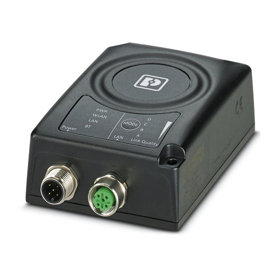
FL EPA 2 FL EPA 2 Characteristics The FL EPA 2 is an industrial wireless module for the wireless integration of industrial Ethernet and PROFINET devices in cable-based networks through WLAN and/or Bluetooth. Among others, the FL EPA 2 is designed for the following typical applications: –... - Page 8 FL EPA 2 8 / 50 PHOENIX CONTACT 108452_en_01...
-
Page 9: Installation
Installation Installation Mechanical installation Figure 3-1 Assembly drawing (all dimensions in mm, antenna connection for the FL EPA 2 RSMA only) 9 / 50 108452_en_01 PHOENIX CONTACT... -
Page 10: Din Rail Mounting
FL EPA 2 3.1.1 DIN rail mounting The FL EPA RMS mounting kit (Order No. 2701133) is available as an accessory for mounting the device on a 35 mm DIN rail. Figure 3-2 Fixing the EPA to the mounting kit for the DIN rail •... -
Page 11: Wall Or Mast Mounting
Use the two screws provided to fix the EPA to the base plate. • The two 4.5 mm bore holes can be used for mounting. Two steel clamps are provided for mounting the EPA to a mast (25 mm ... 85 mm). 11 / 50 108452_en_01 PHOENIX CONTACT... -
Page 12: Connectors
FL EPA 2 3.1.3 Connectors Figure 3-4 M12 connectors Table 3-1 Power supply (M12 male connector, A-coded) Graphic Function Power supply + (9 V DC - 30 V DC) Digital input ground Power supply ground Digital input + (9 V DC - 30 V DC) -
Page 13: Antenna Connection (Fl Epa 2 Rsma Only)
Installation Antenna connection (FL EPA 2 RSMA only) The device is provided with an RSMA (female) antenna socket. Only use suitable antenna cables and adapters. The antenna socket may be damaged when trying to screw on wrong connectors. Avoid the use of long and/or low-quality antenna cables. They cause additional attenuation and may reduce the range. -
Page 14: Indication Of Received Signal Strength Via The A-B-C-D Leds
FL EPA 2 Table 3-3 Meaning of the LED indicators [...] Color Meaning Bluetooth deactivated Flashing blue NAP mode: Bluetooth activated, no client connected Blue NAP mode: connected to at least one PANU client PANU mode: connected to NAP Flashing blue... -
Page 15: Configuration
AT commands can also be transmitted to the EPA via the web-based management. The AT command reference can be found, for example, in the web-based management application under the “Help” menu item. 15 / 50 108452_en_01 PHOENIX CONTACT... -
Page 16: Easy Config ("Mode" Button)
FL EPA 2 4.0.1 Easy Config (“MODE” button) Figure 4-1 Control panel The MODE button can be used to configure or reset the device. The respective function is carried out when releasing the button (“falling edge”) 4.0.2 Using the MODE button Switch on the device and wait for the Link Quality LEDs to light up and go out again. -
Page 17: Easy Config Via Web Interface
The required mode can be selected under the “Easy Config” menu item. Figure 4-2 “Easy Config” web page The “Set” button is used to activate the required mode. Figure 4-3 “Easy Config” web page 17 / 50 108452_en_01 PHOENIX CONTACT... -
Page 18: Easy Config Modes
FL EPA 2 4.0.4 Easy Config modes Table 4-1 Indication of received signal strength via the A-B-C-D LEDs Mode Role Description Bluetooth Configure the device as a Bluetooth client, PANU then discover devices in mode 4 and config- ure them accordingly as a client... - Page 19 The connection is layer 2-transparent and thus also suitable for PROFINET. For functionally safe communication, please refer to the information in Section “Safety- related communication (PROFISafe/SafetyBridge)” on page 19 / 50 108452_en_01 PHOENIX CONTACT...
- Page 20 FL EPA 2 20 / 50 PHOENIX CONTACT 108452_en_01...
-
Page 21: Web-Based Management
IP subnet as the wireless bridge. Web-based management is designed for the current versions of Internet Explorer, Chrome, Firefox and Safari. Other browsers may not support the full functionality of the web-based management. Figure 5-1 “System Overview” web page 21 / 50 108452_en_01 PHOENIX CONTACT... - Page 22 FL EPA 2 All changes are activated using the “Safe and Reboot” button. The button will only be active if parameters have been changed. This also applies to changes made to the device on other web pages during this session. Selecting another menu item within the configuration pages does not discard the changes that have been made to the configuration.
-
Page 23: System Overview
The indications are dynamically adapted to the current settings. The “World Mode” function, for example, is only available for the “WLAN-client” operating mode. This entry will not be displayed if the device is configured as an access point. 23 / 50 108452_en_01 PHOENIX CONTACT... -
Page 24: Easy Config
FL EPA 2 5.1.2 Easy Config Figure 5-3 “Easy Config” web page To activate an Easy Config mode, select it from the drop-down menu and click on “Set”. For additional information, please refer to Section 4.0.4 on page 5.1.3 Network settings Figure 5-4 “Network Settings”... -
Page 25: Wlan Settings - Client Mode
The automatic redirect function may not be supported by all browsers. 5.1.4 WLAN settings - Client mode Figure 5-5 “WLAN Settings” web page First select the operating mode (“Access Point” or “Client”). Depending on the selection, there are different input fields available. 25 / 50 108452_en_01 PHOENIX CONTACT... - Page 26 FL EPA 2 Enable - Enable/disable the WLAN interface. Operating Mode - Choose if the device should operate as a WLAN client or access point. Depending on the selection, additional parameters are visible. Channel Bands - “Client” mode only - Choose to scan for networks on either the 2.4 GHz or 5 GHz channel band, or on both (default).
-
Page 27: Regulatory Domains And Wlan Channels
The device for which the MAC address needs to be entered supports layer 2-transparent communication (e.g., for PROFINET) with the network. This mode is suitable for every WLAN-compliant access point. Cloned MAC Address - Enter the MAC address for “Layer 2 cloned MAC only” (see above). 27 / 50 108452_en_01 PHOENIX CONTACT... -
Page 28: Wlan Settings - Access Point Mode
FL EPA 2 5.1.5 WLAN settings - Access point mode Figure 5-7 “WLAN Settings” web page Settings for “Access Point” mode. Network (SSID) - Enter an SSID (network name). Authentication Mode - Select the authentication/encryption mode to use for the access point. -
Page 29: Bluetooth Settings - General
(not with third-party devices). PIN codes must consist of 4 ... 6 digits. Just Works = Encrypted connection without PIN code. Paired Devices - Lists the Bluetooth devices connected to this device. 29 / 50 108452_en_01 PHOENIX CONTACT... -
Page 30: Bluetooth Settings - Mode-Specific
FL EPA 2 5.1.7 Bluetooth settings - Mode-specific Figure 5-9 “Bluetooth Settings” web page “PANU” mode only Scan for Devices - Scans the environment for Bluetooth devices. To connect to a device, select it from the drop-down menu after scanning. - Page 31 Security key, identical to the NAP key – Press the “Scan for Devices” button. If the NAP is located in close proximity, the NAP address can be selected from the drop- down list after just a few seconds. 31 / 50 108452_en_01 PHOENIX CONTACT...
-
Page 32: Bluetooth Settings" Web Page With Example Panu Values
FL EPA 2 Figure 5-11 “Bluetooth settings” web page with example PANU values The MAC address of the Bluetooth module is two hex values higher than the MAC address printed on it. Apply the settings with “Save and Reboot”. Connection in “Connect to Name” mode A connection based on the “Local Name”... - Page 33 After a few seconds, the client connects to the access point (NAP) if it is located in the wireless range. With this type of configuration, the NAP responds to any scanning device. Connection establishment is protected against unauthorized access using the PIN. 33 / 50 108452_en_01 PHOENIX CONTACT...
-
Page 34: Bluetooth Le Settings
FL EPA 2 Figure 5-13 “Bluetooth Settings” web page 5.1.8 Bluetooth LE settings It is recommended to implemented the entire operation of the BLE functions using AT commands. You can use BLE if Bluetooth is enabled (Bluetooth settings/Enable) 34 / 50... -
Page 35: Firmware Update
As of firmware version 1.6.3, the settings are retained as far as possible. The firmware can also be updated using a wireless connection. Afterwards, the device connects to the previous settings again. During the update process, the device must not be disconnected from the supply voltage. 35 / 50 108452_en_01 PHOENIX CONTACT... -
Page 36: At Commands
FL EPA 2 5.1.10 AT commands Figure 5-15 “AT Commands” web page AT commands can be used for setting extended parameters that are not accessible via web-based management, or to read out parameters in text format. It is possible to simultaneously copy a set of commands into the input field. -
Page 37: System Settings
Cancel All Changes - Restores all parameters in the web-based management to the currently active values. Factory Reset - Resets the device to the factory default settings and performs a restart. Setting a secure password for the device is strongly recommended. 37 / 50 108452_en_01 PHOENIX CONTACT... -
Page 38: Restoring The Factory Defaults
FL EPA 2 Restoring the factory defaults The device can be restored to the factory default settings using any of the following methods: • Press and hold the “MODE” button for >10 seconds and then release it. • Execute Easy Config Mode 2. - Page 39 Problems rarely occur from the actual user data but sometimes from multicast or broadcast data. In time-critical applications, we highly recommend to optimize data traffic using properly configured Managed Switches. 39 / 50 108452_en_01 PHOENIX CONTACT...
- Page 40 FL EPA 2 40 / 50 PHOENIX CONTACT 108452_en_01...
-
Page 41: Technical Data And Accessories
Bluetooth 2.1 + EDR Antenna connection method (Internal) Transmission power 10 dBm, maximum Number of wireless interfaces 1 Bluetooth 2.1 + EDR Wireless modules that can be connected Supported profiles PANU (NAP, PAN), GATT (central) 41 / 50 108452_en_01 PHOENIX CONTACT... - Page 42 FL EPA 2 Supply of the module electronics Connection method M12 connector (A-coded, male) Supply voltage 24 V DC Supply voltage range 9 V DC ... 30 V DC Supply current 36 mA, typical (at 24 V DC) Current consumption...
- Page 43 Network cable - NBC-MSD/ 2,0-93E/R4AC SCO - 1407361 Network cable, Ethernet CAT5 (100 Mbps), 4-pos., PUR, RAL 5021 (water blue), shielded, straight M12 SPEEDCON/IP67 connector (D- coding) to straight RJ45/IP20 connector, cable length: 2 m 43 / 50 108452_en_01 PHOENIX CONTACT...
- Page 44 FL EPA 2 Network cable - NBC-MSD/ 5,0-93E/R4AC SCO - 1407362 Network cable, Ethernet CAT5 (100 Mbps), 4-pos., PUR, RAL 5021 (water blue), shielded M12 SPEEDCON/IP67 connector (D-coding) to straight RJ45/IP20 connector, cable length: 5 m Sensor/actuator cable - SAC-4P- 2,0-PUR/M12FS - 1533576 Sensor/actuator cable, 4-pos., PUR, halogen-free, RAL 7021 (black-...
-
Page 45: Appendixes
Section 2 Section 3 Figure 3-1: Assembly drawing (all dimensions in mm, antenna connection for the FL EPA 2 RSMA only) ................9 Figure 3-2: Fixing the EPA to the mounting kit for the DIN rail .......10 Figure 3-3: Fixing the EPA to the mounting kit for wall/mast mounting ....11 Figure 3-4: M12 connectors ..................12... - Page 46 FL EPA 2 Figure 5-14: “Firmware Update” web page ..............35 Figure 5-15: “AT Commands” web page ..............36 Figure 5-16: “AT Commands” web page ..............36 Figure 5-17: “System Settings” web page ...............37 Section 6 Appendix A 46 / 50 PHOENIX CONTACT...
-
Page 47: A 2 List Of Tables
Section 4 Table 4-1: Indication of received signal strength via the A-B-C-D LEDs ....18 Section 5 Table 5-1: Regulatory domains and WLAN channels ...........27 Table 5-2: Default settings (default upon delivery)..........38 Section 6 Appendix A 47 / 50 108452_en_01 PHOENIX CONTACT... - Page 48 FL EPA 2 48 / 50 PHOENIX CONTACT 108452_en_01...
- Page 49 The receipt of technical documentation (in particular user documentation) does not constitute any further duty on the part of Phoenix Contact to furnish information on modifications to products and/or technical documentation. You are responsible to verify the suitability and intended use of the products in your specific application, in particular with regard to observing the applicable standards and regulations.
- Page 50 Should you have any suggestions or recommendations for improvement of the contents and layout of our manuals, please send your comments to: tecdoc@phoenixcontact.com 50 / 50 PHOENIX CONTACT GmbH & Co. KG • Flachsmarktstraße 8 • 32825 Blomberg • Germany phoenixcontact.com...
- Page 52 PHOENIX CONTACT GmbH & Co. KG Flachsmarktstraße 8 32825 Blomberg, Germany Phone: +49 5235 3-00 Fax: +49 5235 3-41200 E-mail: info@phoenixcontact.com phoenixcontact.com...
Need help?
Do you have a question about the FL EPA 2 and is the answer not in the manual?
Questions and answers