Sign In
Upload
Manuals
Brands
Phoenix Contact Manuals
Industrial Equipment
UM EN FLX ASI SYS PRO INST
Phoenix Contact UM EN FLX ASI SYS PRO INST Manuals
Manuals and User Guides for Phoenix Contact UM EN FLX ASI SYS PRO INST. We have
1
Phoenix Contact UM EN FLX ASI SYS PRO INST manual available for free PDF download: User Manual
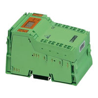
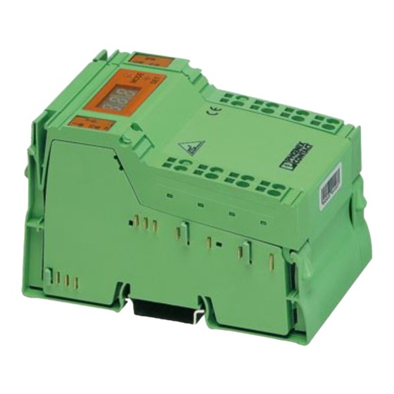
Phoenix Contact UM EN FLX ASI SYS PRO INST User Manual (92 pages)
Brand:
Phoenix Contact
| Category:
Industrial Equipment
| Size: 2 MB
Table of Contents
Table of Contents
7
Fieldline Extension and the AS-Interface System
11
Fieldline Extension AS-Interface Product Group
11
For Your Safety
12
Correct Usage
12
Regulations
12
Safety Notes
12
Documentation for AS-I Devices
13
Function Description of the AS-Interface System
13
Easy Handling
14
Information Content of Data Telegrams
14
Communication Principle
14
Time Response
14
AS-Interface Standardization
15
AS-Interface Specification
15
AS-Interface Profile
16
Profile Structure
16
Different Data Transmission Types (Single/Combined Transaction)
17
System Components of the AS-Interface System
18
Masters/Gateways
18
Power Supply Units
18
Slaves
18
Cable
19
Topology
19
AS-Interface Masters/Gateways
21
AS-Interface Master for Inline (ASI MA IL UNI)
22
Description
22
Housing Dimensions
23
Function
23
Mounting the AS-Interface Master for Inline (ASI MA IL UNI)
24
Connecting the AS-Interface Master for Inline (ASI MA IL UNI)
26
Power Supply and AS-I Connection Method
27
Diagnostic and Status Indicators
27
Buttons
28
7-Segment Display
29
Removing the AS-Interface Master for Inline (ASI MA IL UNI)
29
AS-Interface Gateway for PROFIBUS with Standard Function FLX ASI MA PB SF
30
Description
30
Housing Dimensions
31
Function
31
Mounting/Demounting the Master FLX ASI MA PB SF
32
Connecting the Master FLX ASI MA PB SF
32
Power Supply and AS-I Connection Method
33
Diagnostic and Status Indicators
34
Buttons
34
AS-Interface Gateway for PROFIBUS with Extended Function FLX ASI MA 2 PB EF
35
Description
35
Housing Dimensions
36
Function
36
Mounting/Demounting the Master FLX ASI MA 2 PB EF
38
Connecting the Master FLX ASI MA 2 PB EF
39
Power Supply and AS-I Connection Method
40
Diagnostic and Status Indicators
41
Buttons
41
Power Supply Units
43
Description
43
Product Versions for the AS-Interface System
44
Function
44
Housing Dimensions of the Power Supply Units
45
Mounting/Removing Power Supply Units
46
Mounting on the DIN Rail (Narrow Mounting Position)
46
Mounting on the DIN Rail (Flat Mounting Position)
47
Connecting the Power Supply Units
47
Slaves
49
Description for Fieldline Extension AS-I M12 Devices
49
Housing Versions for Fieldline Extension AS-I M12 Devices
50
Housing Dimensions of Fieldline Extension AS-I M12 Devices
51
Basic Structure of Fieldline Extension AS-I M12 Devices
52
Mounting Fieldline Extension AS-I M12 Devices
53
Flat-Ribbon Cable
55
Penetration Technique
56
Connecting AS-Interface and the Auxiliary Voltage aux to M12 Devices
57
Pin Assignment of the Inputs and Outputs
58
Labeling Fieldline Extension AS-I M12 Devices
59
Diagnostic and Status Indicators of Fieldline Extension AS-I M12 Devices
60
Setting the Address for Fieldline Extension AS-I M12 Devices
61
Replacing the Electronics Module
62
Description for Fieldline Extension AS-I M8 Devices
63
Housing Versions for Fieldline Extension AS-I M8 Devices
64
Housing Dimensions of Fieldline Extension AS-I M8 Devices
65
Basic Structure of Fieldline Extension AS-I M8 Devices
66
Mounting Fieldline Extension AS-I M8 Devices
67
Connecting AS-Interface and the Auxiliary Voltage aux to M8 Devices
68
Pin Assignment of the AS-I Connection
68
Pin Assignment of the Inputs and Outputs
69
Labeling Fieldline Extension AS-I M8 Devices
69
Diagnostic and Status Indicators of Fieldline Extension AS-I M8 Devices
70
Setting the Address for Fieldline Extension AS-I M8 Devices
71
Description for AS-I Control Cabinet Modules
72
Product Versions for AS-I Control Cabinet Modules
72
Description for ASI IO ME DI 4 AB
73
Description for ASI IO ME DIO 4/3 AB
74
Description for ASI IO ME DIO 4/4 AB
75
Housing Dimensions of Control Cabinet Modules
76
Mounting Control Cabinet Modules
76
Connecting Cables
76
Terminal Assignment of Control Cabinet Modules
77
Diagnostic and Status Indicators of Control Cabinet Modules
78
Setting the Address for Control Cabinet Modules
79
Setting the Sensor Power Supply
80
Configuration
83
Number of Inputs and Outputs
83
Position of Inputs and Outputs in the Application
83
Required Current in an AS-I System
83
Selecting the Cable
84
Speed of Data Exchange
84
Integrating the AS-I System in the Control System
85
AS-Interface in the Control Cabinet
85
General Information about Installation
87
Interference Suppression Measures
88
Installation Instructions
89
Mounting Distances
89
Startup
91
Mounting and Installation
91
Address Assignment
91
Configuring the Master
92
Operation
92
Advertisement
Advertisement
Related Products
Phoenix Contact UM EN PROFICLOUD
Phoenix Contact UM EN BLUEMARK LED
Phoenix Contact UM EN FL SWITCH SMCS Series
Phoenix Contact UM EN ASI CC ADR
Phoenix Contact UM EN FL WLAN EPA
Phoenix Contact UNO2-PS/1AC/24DC/120W
Phoenix Contact 1005869
Phoenix Contact 1005955
Phoenix Contact 1005957
Phoenix Contact 1012015
Phoenix Contact Categories
Controller
Switch
Control Unit
Power Supply
Media Converter
More Phoenix Contact Manuals
Login
Sign In
OR
Sign in with Facebook
Sign in with Google
Upload manual
Upload from disk
Upload from URL