Table of Contents
Advertisement
Quick Links
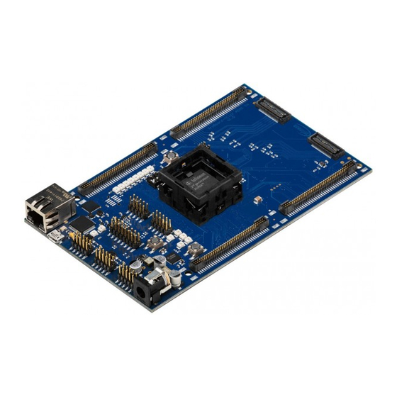
TriBoard TC3X3
TriBoard Man ual T C3X3
Hardwar e: T riBoard TC3X3 TH V1.0 and Tr iBoar d T C3X3 V1.0
About this document
Scope and purpose
The User Manual provide information about using, configuration and connecting the TriBoard with Infineon
AURIX™ TC3X3 TQFP device (0.4mm pitch). The manual provide information for different hardware types. There
exist different hardware with Through Hole socket (TriBoard TC3X3 TH) and soldered devices (TriBoard TC3X3).
The schematic is identically for the all boards if not other mentioned in chapter schematic. The placing on the
boards is the same, all components are on the same location.
Intended audience
Design, verfication, test and software engineers will use this document to get an understanding of the
functionality and connections of the TriBoard.
User Manual
www.infineon.com
Please read the Important Notice and Warnings at the end of this document
TriBoard TC3X3 TH V1.0 and TriBoard TC3X3 V1.0
V1.0
2020-05
Advertisement
Table of Contents

Related Manuals for Infineon TriBoard TC3X3 Series


Summary of Contents for Infineon TriBoard TC3X3 Series
- Page 1 About this document Scope and purpose The User Manual provide information about using, configuration and connecting the TriBoard with Infineon AURIX™ TC3X3 TQFP device (0.4mm pitch). The manual provide information for different hardware types. There exist different hardware with Through Hole socket (TriBoard TC3X3 TH) and soldered devices (TriBoard TC3X3).
-
Page 2: Table Of Contents
TriBoard Manual TC3X3 Hardware: TriBoard TC3X3 TH V1.0 and TriBoard TC3X3 V1.0 Table of Contents Table of Contents About this document............Preface-1 Table of Contents . -
Page 3: Table Of Contents
TriBoard Manual TC3X3 Hardware: TriBoard TC3X3 TH V1.0 and TriBoard TC3X3 V1.0 Table of Contents Debug Signals ................5-2 Peripheral Signals . -
Page 4: Introduction
TriBoard Manual TC3X3 Hardware: TriBoard TC3X3 TH V1.0 and TriBoard TC3X3 V1.0 Introduction Introduction We congratulate you on your purchase of the TriCore™ Evaluation Board. This kit is a versatile tool, providing quick access to the capabilities of TriCore™’s powerful architecture. Applications can be developed easily. -
Page 5: Features
Hardware: TriBoard TC3X3 TH V1.0 and TriBoard TC3X3 V1.0 Features Features Summary of Features – Infineon’s TC3X3 (TC333, TC323) AURIX™ 2G Controller in TQFP-100 Package (0.4mm pitch) – FlexRay™ Transceivers – High Speed CAN Transceivers (CAN-FD capable) – USB to UART bridge –... -
Page 6: Block Diagram
TriBoard Manual TC3X3 Hardware: TriBoard TC3X3 TH V1.0 and TriBoard TC3X3 V1.0 Features – 4-pin Dip switch Zero Ohm Bridges Zero Ohm resistors give the flexibility to configure the systems functionality. Block Diagram XTAL CAN0 TxCAN03 RxCAN03 Transceiver CAN1 TxCAN01 RxCAN01 TC3X3 (e.g. -
Page 7: Placement
TriBoard Manual TC3X3 Hardware: TriBoard TC3X3 TH V1.0 and TriBoard TC3X3 V1.0 Features Placement X604 X601 S202 Y401 D302 D303 D304 D305 D306 D307 D308 D309 U401 X404 D401 D402 T301 U201 X402 T302 D504 D507 U502 D506 X502 C303 D508 D505 X406... -
Page 8: Triboard Information
• None Power Supply All needed voltages are generated via Infineon’s Multi Voltage Safety Micro Processor Supply TLF35584QV and via the microcontroller itself (+1,25V). The supply device is available as two different devices: TLF35584QVVS1 -> +5V standby voltage, +5V TriCore™ supply (V_UC) TLF35584QVVS2 ->... -
Page 9: Failsafe Handling
TriBoard Manual TC3X3 Hardware: TriBoard TC3X3 TH V1.0 and TriBoard TC3X3 V1.0 TriBoard Information 3.3.1 Failsafe handling In case that the device don’t contains a program which disable or service the window watchdog and error pin monitor of the TLF35584 then the TLF35584 is going to a FAILSAFE state where all supplies are switched off. This state can be left via reconnect the power plug or via the ENA button (S502). -
Page 10: Clock
TriBoard Manual TC3X3 Hardware: TriBoard TC3X3 TH V1.0 and TriBoard TC3X3 V1.0 TriBoard Information Clock On the board is a fixed crystal with 20MHz assembled. You can change this by replacing Y101 (soldered). USB Connector The USB connector is used for connection to a PC. Via the USB it is possible to power the board, using the ASCLIN0 as serial connection via USB and Debugging via DAS. -
Page 11: Miniwiggler Jds
TriBoard Manual TC3X3 Hardware: TriBoard TC3X3 TH V1.0 and TriBoard TC3X3 V1.0 TriBoard Information 3.6.2 miniWiggler JDS The miniWiggler JDS is a low cost debug tool which allows you access to the JTAG of the device. Make sure that you have the latest DAS release. Debugging is possible via the DAS Server ‘UDAS‘. Please contact your prefered debug vendor for support of DAS. -
Page 12: Adc
TriBoard Manual TC3X3 Hardware: TriBoard TC3X3 TH V1.0 and TriBoard TC3X3 V1.0 TriBoard Information The LIN can be used in master and in slave mode. For the master mode there is per default a pull-up of 1K (R360) and a capacitor of 1nF (C304) on the BUS assembled. For using the LIN in slave mode the pull-up resistor R360 must be removed and maybe the capacitor changed to a smaller value (e.g. - Page 13 TriBoard Manual TC3X3 Hardware: TriBoard TC3X3 TH V1.0 and TriBoard TC3X3 V1.0 TriBoard Information X604 X601 S202 R390 R399 X404 Y401 R392 R393 R394 R395 R396 R397 R398 R402 R346 R403 U401 CB309 R524 R348 CB414 CB402 U407 U408 D401 D402 U406 R236...
-
Page 14: Other Peripherals
TriBoard Manual TC3X3 Hardware: TriBoard TC3X3 TH V1.0 and TriBoard TC3X3 V1.0 TriBoard Information 3.12 Other peripherals For all other peripherals there are no special plugs on the board. The peripheral signals are available on the different connectors. See “Connector Pin Assignment” on Page 6-1. -
Page 15: High Speed With Dap
TriBoard Manual TC3X3 Hardware: TriBoard TC3X3 TH V1.0 and TriBoard TC3X3 V1.0 TriBoard Information 3.15.4 High speed with DAP For use the DAP connection with 160 MHz you need to remove 3 resistors to have a very short connection between device and connector. - Page 16 TriBoard Manual TC3X3 Hardware: TriBoard TC3X3 TH V1.0 and TriBoard TC3X3 V1.0 TriBoard Information Because the device don’t have a VDDSB pin the 1,25V standby supply pin of the connector is not connected on this board. User Manual V1.0 TriBoard TC3X3 TH V1.0 and TriBoard TC3X3 V1.0 2020-05...
-
Page 17: Triboard Configuration
TriBoard Manual TC3X3 Hardware: TriBoard TC3X3 TH V1.0 and TriBoard TC3X3 V1.0 TriBoard Configuration TriBoard Configuration HW Boot Configuration Figure 4-1 HW Configuration DIP-Switches The picture above shows the definition of the boot HW configuration switch. The meaning of the switches will be described in the following table (Table 4-1). -
Page 18: Assembly Options
TriBoard Manual TC3X3 Hardware: TriBoard TC3X3 TH V1.0 and TriBoard TC3X3 V1.0 TriBoard Configuration Assembly Options 4.2.1 General optional resistors Table 4-2 General optional resistors (default assembly in brackets) Component Description R202 Connect P20.2 (/TESTMODE) to GND (not assembled) R203 XTAL1 Rload (50 Ohm) (not assembled) R206 XTAL Rparallel (not assembled) - Page 19 TriBoard Manual TC3X3 Hardware: TriBoard TC3X3 TH V1.0 and TriBoard TC3X3 V1.0 TriBoard Configuration X604 X601 S202 R390 R399 X404 Y401 R392 R393 R394 R395 R396 R397 R398 R402 R346 R403 U401 CB309 R524 R348 CB414 CB402 U407 U408 D401 D402 U406 R236...
-
Page 20: Resistors For Peripherals
TriBoard Manual TC3X3 Hardware: TriBoard TC3X3 TH V1.0 and TriBoard TC3X3 V1.0 TriBoard Configuration 4.2.2 Resistors for peripherals Table 4-3 Resistors for peripherals (default assembly in brackets) Component Description R220 Connect V_VR with VDDM (assembled) R221 Connect +3V3 with VDDM (not assembled) R222 Connect VAREF1 with VDDM (assembled) R301... - Page 21 TriBoard Manual TC3X3 Hardware: TriBoard TC3X3 TH V1.0 and TriBoard TC3X3 V1.0 TriBoard Configuration X604 X601 S202 R390 R399 X404 Y401 R392 R393 R394 R395 R396 R397 R398 R402 R346 R403 U401 CB309 R524 R348 CB414 CB402 U407 U408 D401 D402 U406 R236...
-
Page 22: Signal (On Board Used) Description
TriBoard Manual TC3X3 Hardware: TriBoard TC3X3 TH V1.0 and TriBoard TC3X3 V1.0 Signal (on board used) Description Signal (on board used) Description For more information about the signals please see the user manual/datasheet for TC3X3 and/or the schematics of the board. All not mentioned signals are not used on the board and can be used outside. -
Page 23: Config Signals
TriBoard Manual TC3X3 Hardware: TriBoard TC3X3 TH V1.0 and TriBoard TC3X3 V1.0 Signal (on board used) Description Config Signals Table 5-3 Config Signals Short name Description P14.5 HWCFG1 (EVR33OFF / EVR33ON) P14.3 HWCFG3 (Boot from pins / Boot from Flash BMI) P10.5 HWCFG4 (see boot configuration Table... - Page 24 TriBoard Manual TC3X3 Hardware: TriBoard TC3X3 TH V1.0 and TriBoard TC3X3 V1.0 Signal (on board used) Description Table 5-6 Peripheral Signals (continued) Short name Description P15.2 CAN01 Transmit Output ASCLIN0 Transmit Output (optional) P15.1 ASCLIN1 Receive Input A P15.0 ASCLIN1 Transmit Output P11.10 CAN03 Receive Input D P11.12...
-
Page 25: Connector Pin Assignment
TriBoard Manual TC3X3 Hardware: TriBoard TC3X3 TH V1.0 and TriBoard TC3X3 V1.0 Connector Pin Assignment Connector Pin Assignment The TriBoard will be shipped with four male (plug) connectors on top layer and four female (socket) connectors on bottom layer. The default connectors are 80-pol. Board to Board connectors from Samtec: http://www.samtec.com Plug: FTSH-140-02-L-DV-ES-A... -
Page 26: Tc3X3 Connector / Top View
TriBoard Manual TC3X3 Hardware: TriBoard TC3X3 TH V1.0 and TriBoard TC3X3 V1.0 Connector Pin Assignment TC3X3 Connector / Top View BUS EXPANSION (X601,X701) PERIPHERALS (X602,X702) P21.6 VCC_IN VCC_IN P21.7 VCC_IN VCC_IN 9 10 9 10 11 12 11 12 13 14 13 14 15 16 /ESR1... - Page 27 TriBoard Manual TC3X3 Hardware: TriBoard TC3X3 TH V1.0 and TriBoard TC3X3 V1.0 Connector Pin Assignment ADC (X603, X703) GTM / PORTS (X604,X704) 9 10 P02.0 9 10 11 12 P02.1 11 12 13 14 P02.2 13 14 15 16 P02.3 15 16 17 18 P02.4...
-
Page 28: Power Connector Pinout
TriBoard Manual TC3X3 Hardware: TriBoard TC3X3 TH V1.0 and TriBoard TC3X3 V1.0 Connector Pin Assignment Power connector pinout +3,5V...40V Figure 6-3 Power connector pinout (Roka 520 2550 USB connector pinout Figure 6-4 USB connector pinout (Micro USB B-type) FlexRay™ (ERAY) connector pinout Figure 6-5 FlexRay™... -
Page 29: Lin Connector Pinout
TriBoard Manual TC3X3 Hardware: TriBoard TC3X3 TH V1.0 and TriBoard TC3X3 V1.0 Connector Pin Assignment LIN connector pinout Figure 6-7 LIN connector pinout (IDC10) OCDS1 connector pinout Figure 6-8 OCDS1 connector pinout (IDC16) DAP connector pinout Figure 6-9 DAP connector pinout (Samtec FTSH10) User Manual V1.0 TriBoard TC3X3 TH V1.0 and TriBoard TC3X3 V1.0... -
Page 30: Etk Connector Pinout
TriBoard Manual TC3X3 Hardware: TriBoard TC3X3 TH V1.0 and TriBoard TC3X3 V1.0 Connector Pin Assignment 6.10 ETK connector pinout Figure 6-10 ETK connector pinout (Samtec TFM-105) 6.11 Ethernet miniWiggler power connector pinout Figure 6-11 Ethernet miniWiggler connector pinout (JST B4B-PH) User Manual V1.0 TriBoard TC3X3 TH V1.0 and TriBoard TC3X3 V1.0... -
Page 31: Schematic And Layout
TriBoard Manual TC3X3 Hardware: TriBoard TC3X3 TH V1.0 and TriBoard TC3X3 V1.0 Schematic and Layout Schematic and Layout Known problems 7.1.1 Known problems on TriBoard TC3X3 TH V1.0 No problems known. 7.1.2 Known problems on TriBoard TC3X3 V1.0 No problems known. Schematic User Manual V1.0... - Page 32 TriBoard Manual TC3X3 Hardware: TriBoard TC3X3 TH V1.0 and TriBoard TC3X3 V1.0 Schematic and Layout Figure 7-1 Schematic - Project User Manual V1.0 TriBoard TC3X3 TH V1.0 and TriBoard TC3X3 V1.0 2020-05...
- Page 33 TriBoard Manual TC3X3 Hardware: TriBoard TC3X3 TH V1.0 and TriBoard TC3X3 V1.0 Schematic and Layout Figure 7-2 Schematic - Clock, Config, Debug, Ports and ADC User Manual V1.0 TriBoard TC3X3 TH V1.0 and TriBoard TC3X3 V1.0 2020-05...
- Page 34 TriBoard Manual TC3X3 Hardware: TriBoard TC3X3 TH V1.0 and TriBoard TC3X3 V1.0 Schematic and Layout Figure 7-3 Schematic - On Board Peripherals User Manual V1.0 TriBoard TC3X3 TH V1.0 and TriBoard TC3X3 V1.0 2020-05...
- Page 35 TriBoard Manual TC3X3 Hardware: TriBoard TC3X3 TH V1.0 and TriBoard TC3X3 V1.0 Schematic and Layout Figure 7-4 Schematic - miniWiggler JDS and Debug connectors User Manual V1.0 TriBoard TC3X3 TH V1.0 and TriBoard TC3X3 V1.0 2020-05...
- Page 36 TriBoard Manual TC3X3 Hardware: TriBoard TC3X3 TH V1.0 and TriBoard TC3X3 V1.0 Schematic and Layout Figure 7-5 Schematic - Power Supply User Manual V1.0 TriBoard TC3X3 TH V1.0 and TriBoard TC3X3 V1.0 2020-05...
- Page 37 TriBoard Manual TC3X3 Hardware: TriBoard TC3X3 TH V1.0 and TriBoard TC3X3 V1.0 Schematic and Layout Figure 7-6 Schematic - Connectors (Plug) User Manual V1.0 TriBoard TC3X3 TH V1.0 and TriBoard TC3X3 V1.0 2020-05...
- Page 38 TriBoard Manual TC3X3 Hardware: TriBoard TC3X3 TH V1.0 and TriBoard TC3X3 V1.0 Schematic and Layout Figure 7-7 Schematic - Connectors (Socket) User Manual V1.0 TriBoard TC3X3 TH V1.0 and TriBoard TC3X3 V1.0 2020-05...
-
Page 39: Layout
TriBoard Manual TC3X3 Hardware: TriBoard TC3X3 TH V1.0 and TriBoard TC3X3 V1.0 Schematic and Layout Layout Figure 7-8 Component Plot Top Layer User Manual V1.0 TriBoard TC3X3 TH V1.0 and TriBoard TC3X3 V1.0 2020-05... - Page 40 TriBoard Manual TC3X3 Hardware: TriBoard TC3X3 TH V1.0 and TriBoard TC3X3 V1.0 Schematic and Layout Figure 7-9 Component Plot Bottom Layer User Manual 7-10 V1.0 TriBoard TC3X3 TH V1.0 and TriBoard TC3X3 V1.0 2020-05...
-
Page 41: Layout With Dimensioning
TriBoard Manual TC3X3 Hardware: TriBoard TC3X3 TH V1.0 and TriBoard TC3X3 V1.0 Schematic and Layout Layout with Dimensioning The following dimensions should be used for development of extension boards. Figure 7-10 Dimensioning (mm) User Manual 7-11 V1.0 TriBoard TC3X3 TH V1.0 and TriBoard TC3X3 V1.0 2020-05... - Page 42 TriBoard Manual TC3X3 Hardware: TriBoard TC3X3 TH V1.0 and TriBoard TC3X3 V1.0 Schematic and Layout Figure 7-11 Dimensioning (mil) The dimensioning is valid for all TriBoards. User Manual 7-12 V1.0 TriBoard TC3X3 TH V1.0 and TriBoard TC3X3 V1.0 2020-05...
- Page 43 TriBoard Manual TC3X3 Hardware: TriBoard TC3X3 TH V1.0 and TriBoard TC3X3 V1.0 Revision History Page or Item Subjects (major changes since previous revision) V1.0, 2020-05 First version User Manual RevisionHistory-1 V1.0 TriBoard TC3X3 TH V1.0 and TriBoard TC3X3 V1.0 2020-05...
- Page 44 Infineon Technologies, Infineon Technologies in customer's applications. Document reference Infineon Technologies’ products may not be used in The data contained in this document is exclusively Doc_Number any applications where a failure of the product or any intended for technically trained staff.
Need help?
Do you have a question about the TriBoard TC3X3 Series and is the answer not in the manual?
Questions and answers